Page 8
PDUAC3U SERIES
OPERATING MANUAL
POWERING TECHNOLOGY
Manual No. pduac3u-3 pduac3u-man-rev3-0317.indd
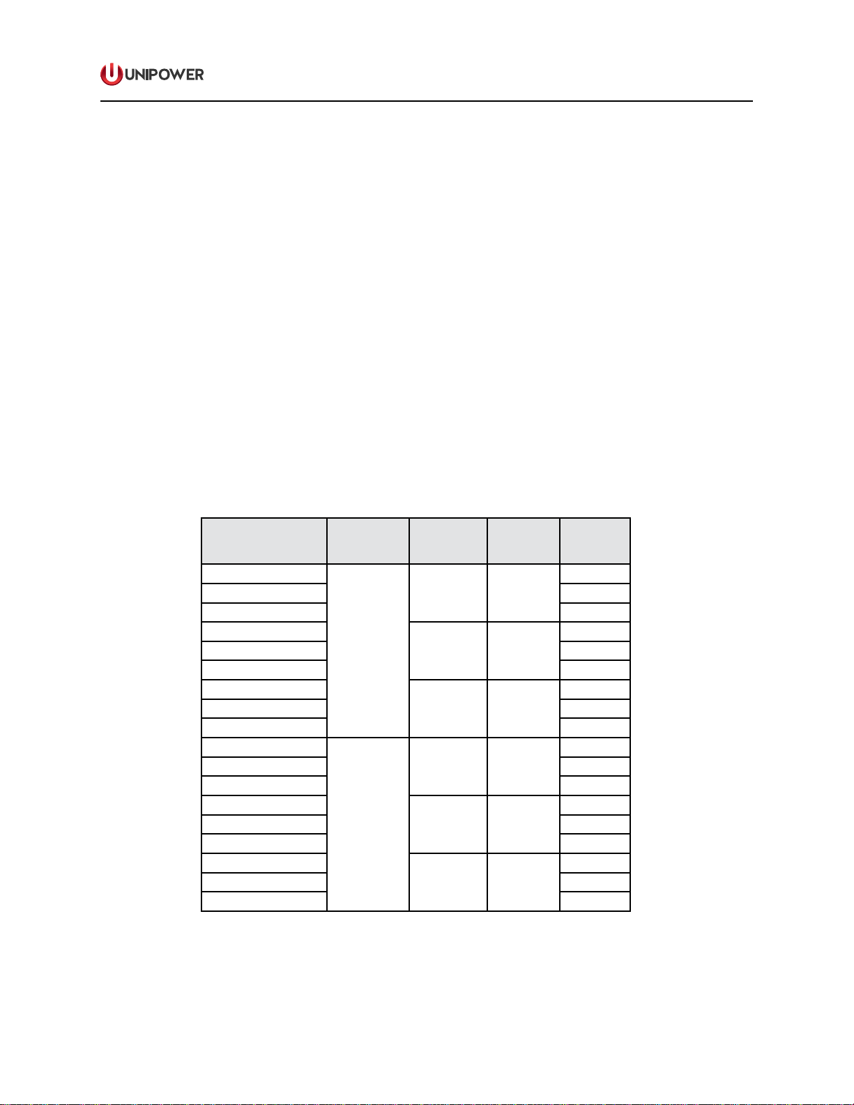
7.0 SPECIFICATIONS
The following specications are typical at 25°C unless otherwise noted.
INPUT/OUTPUT
Input Voltage............................3-phase, 120/208 or 230/400VAC
4 wire & GND
Input Current...............................................100A Max. per phase
Load Circuit Breakers
-04 ...............................................................................4 x 25A
-08 ...............................................................................8 x 25A
-12 .............................................................................12 x 25A
Output Voltage Range
-120 .......................................................................85-132VAC
-208 .....................................................................180-264VAC
-230 .....................................................................180-264VAC
Frequency........................................................................47-63Hz
REGULATORY
Safety Certications....................................................UL60950-1
CSA22.2 No. 60950-1 2nd Ed.
EN60950-1 2nd Ed.
Line Conducted Emissions................. FCC20780 pt.15J Curve A
EN55022 Class A
Fast Transient Immunity..........................................EN61000-4-4
Surge Immunity .......................................................EN61000-4-5
ENVIRONMENTAL
Operating Temp. Range .........................................-20°C to 50°C
Storage Temp. Range...........................................-40°C to +85°C
Humidity..........................................0% to 90%, Non-Condensing
PHYSICAL SPECIFICATIONS
Case Material/Finish............................ Steel/Black Powder Coat
Dimensions, Inches (mm) .........................5.1h x 16.75w x 11.5d
(43.2 x 425.5 x 292.1)
Rack Mounting................................................19” or 23”, 3U High
Weight ...................................................................23lbs (10.5Kg)
FIELD WIRING CONNECTIONS
Input (L1, L2, L3, N, GND).....Cable Compression, #2AWG max.
Output (L & LN) ..................................................No. 6-32 Screws
Output (Ground) .................................................No. 8-32 Screws
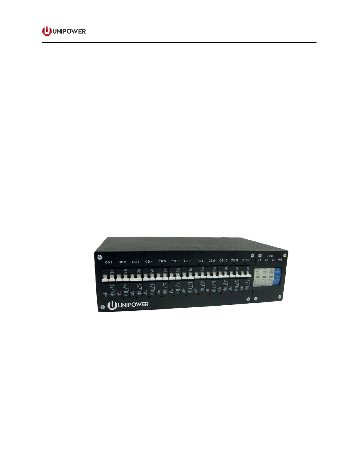
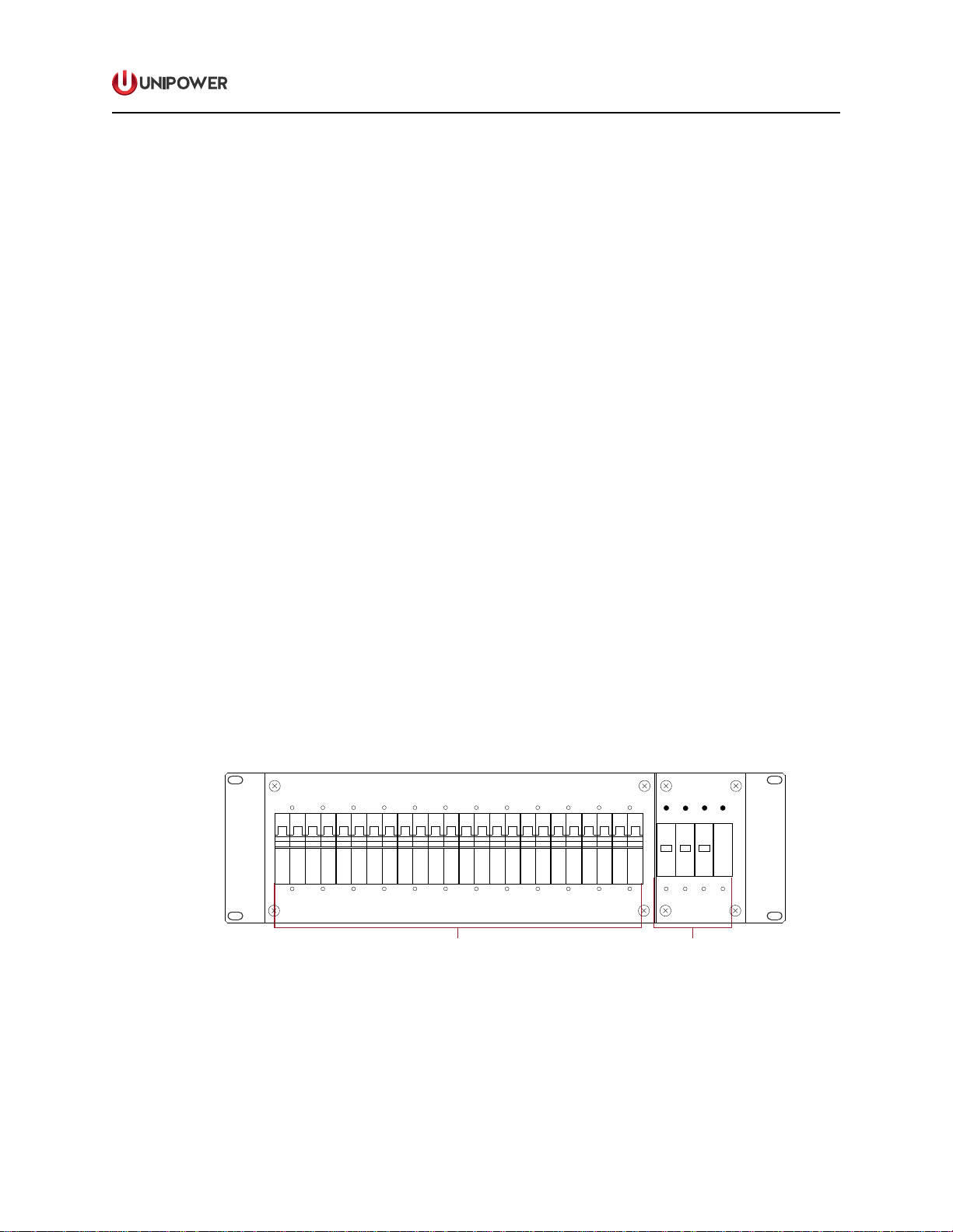
8.0 FRONT PANEL DESCRIPTION
Thefront panelof the PDUAC3U,shown inFigure 3below, consistsof twosections.
The left section contains the output circuit breakers; there are 4, 8 or 12 tted
depending on the exact model. They are each rated at 25Aas standard. The right
section accommodates an optional surge protection feature. When this option is
not tted blanking panels are installed.
LOAD DISTRIBUTION BREAKERS
(4, 8 or 12 x 25A)
INPUT
AC SURGE PROTECTION
O/
OFF
25A
I/
ON
O/
OFF
25A
I/
ON
O/
OFF
25A
I/
ON
O/
OFF
25A
I/
ON
O/
OFF
25A
I/
ON
O/
OFF
25A
I/
ON
O/
OFF
25A
I/
ON
O/
OFF
25A
I/
ON
O/
OFF
25A
I/
ON
O/
OFF
25A
I/
ON
O/
OFF
25A
I/
ON
O/
OFF
25A
I/
ON
V20-CV20-CV20-C C25-B+C
N-PE
CB1 CB2 CB3 CB4 CB5 CB6 CB7 CB8 CB9 CB10 CB11 CB12
L1 L2 L3 NPE
SPD
Figure 3. Front Panel View


 User manual")