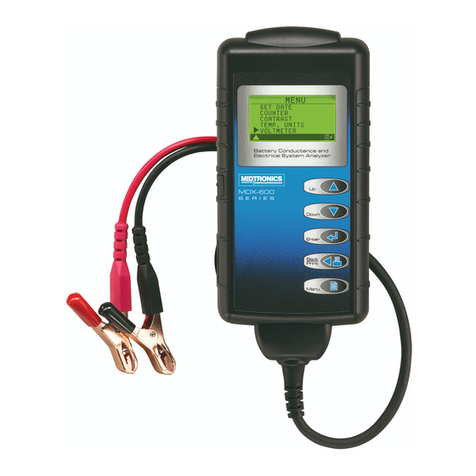
Midtronics Inc. 7000 Monroe Street Willowbrook, IL 60527 www.midtronics.com
10
Chapter 1: Introduction & Overview EXP-1003 HD
Print/View Menu
The tester stores the last battery, system, and cable
test results in its memory until you perform another
test. To review or print results before you retest, select
a test type in the Print/View Menu.
Menu Icon Description
Displays the last Battery and System Test
results. Sends the results to an optional IR
printer.
Displays the last Cable Drop Test result. Sends
the result to an optional IR printer.
Logging In
Scroll to a User ID and press NEXT.
1USER01
2USER02
3USER03
4USER04
To create a new User ID, scroll to a placeholder (USER01,
USER02, etc.), press NEXT and select the Users function in the
Utility Menu. See “Users”for instructions.
Creating a User ID and Setting Preferences
When you press the POWER button, the analyzer takes a few
seconds to boot up while testing the integrity of its software. It
then displays a list of default User IDs, which are placeholders
for adding technicians to the test database. To edit the default
IDs and add up to 24 technicians, see the Utility Menu.
Before starting a test you may want to customize the use of
your tester by setting preferences in the Utility Menu. The
menu has settings for the date and time, the display contrast
and backlight time, customer coupons, languages, and more.
Inspecting the Battery
Before starting the test visually inspect the battery for:
•Cracked, buckled, or leaking case. If you see any of these
defects, replace the battery.
•Corroded, loose, or damaged cables and connections. Re-
pair or replace them as needed.
•Corrosion on the battery terminals, and dirt or acid on the
case top. Clean the case and terminals using a wire brush
and a mixture of water and baking soda.
•Low electrolyte level. If the electrolyte level is too low,
add distilled water to ll up to ½ inch above the top of the
plates and fully charge the battery. Do not overll.
•Corroded or loose battery tray and hold-down xture.
Tighten or replace as needed.
Connecting to a Battery
Do not connect the tester to a voltage source
greater than 60 Vdc.
Testing Individual Batteries
At the start of the test, make sure all vehicle accessory loads
are o, the key is not in the ignition, and the doors are closed.
1. If the batteries have threaded studs, screw the negative (–)
stud adapter onto the negative terminal, and the positive
(+) adapter onto the positive terminal.
Failure to properly install lead terminal adapters,
or using adapters that are dirty or worn, may
cause false test results.
When testing side-post or Group 31 batteries, always use lead
terminal adapters provided with the tester—do not test at
the battery’s steel bolts. To avoid damage, never use a wrench
to tighten the adapters more than ¼ turn.
2. Connect the red clamp to the positive (+) terminal or
adapter.
3. Connect the black clamp to the negative (–) terminal or
adapter.
4. For a proper connection, rock the clamps back and forth.
Both sides of the clamp must be rmly connected before
testing. If the message CHECK CONNECTION appears, clean
the terminals and/or reconnect the clamps
Clamp connection to stud adapter
Clamp connection to stud pad


