IFM ZZ0600 Manual

Instructions for set-up
Fluid monitoring system
Application package
11274130 / 00 10 / 2019
UK

Fluid monitoring system - Application package
2
Contents
1 Preliminary note � � � � � � � � � � � � � � � � � � � � � � � � � � � � � � � � � � � � � � � � � � � � � � � � � � � � � � � � � � � � � � � � � � � �3
1�1 Symbols used � � � � � � � � � � � � � � � � � � � � � � � � � � � � � � � � � � � � � � � � � � � � � � � � � � � � � � � � � � � � � � � � � �3
1�2 Further documents � � � � � � � � � � � � � � � � � � � � � � � � � � � � � � � � � � � � � � � � � � � � � � � � � � � � � � � � � � � � � �3
2 Safety instructions � � � � � � � � � � � � � � � � � � � � � � � � � � � � � � � � � � � � � � � � � � � � � � � � � � � � � � � � � � � � � � � � � �4
3 Functions and features � � � � � � � � � � � � � � � � � � � � � � � � � � � � � � � � � � � � � � � � � � � � � � � � � � � � � � � � � � � � � � �4
4 System requirements � � � � � � � � � � � � � � � � � � � � � � � � � � � � � � � � � � � � � � � � � � � � � � � � � � � � � � � � � � � � � � � �4
5 Function � � � � � � � � � � � � � � � � � � � � � � � � � � � � � � � � � � � � � � � � � � � � � � � � � � � � � � � � � � � � � � � � � � � � � � � � � �4
5�1 Fluid monitoring system � � � � � � � � � � � � � � � � � � � � � � � � � � � � � � � � � � � � � � � � � � � � � � � � � � � � � � � � � �4
5�2 IO-Link master � � � � � � � � � � � � � � � � � � � � � � � � � � � � � � � � � � � � � � � � � � � � � � � � � � � � � � � � � � � � � � � � �5
6 Installation� � � � � � � � � � � � � � � � � � � � � � � � � � � � � � � � � � � � � � � � � � � � � � � � � � � � � � � � � � � � � � � � � � � � � � � � �5
6�1 Fluid monitoring system � � � � � � � � � � � � � � � � � � � � � � � � � � � � � � � � � � � � � � � � � � � � � � � � � � � � � � � � � �5
6�2 IO-Link master � � � � � � � � � � � � � � � � � � � � � � � � � � � � � � � � � � � � � � � � � � � � � � � � � � � � � � � � � � � � � � � � �5
6�3 Power supply � � � � � � � � � � � � � � � � � � � � � � � � � � � � � � � � � � � � � � � � � � � � � � � � � � � � � � � � � � � � � � � � � �5
7 Electrical connection� � � � � � � � � � � � � � � � � � � � � � � � � � � � � � � � � � � � � � � � � � � � � � � � � � � � � � � � � � � � � � � � �6
4�1 Pin assignment of the IO-Link master � � � � � � � � � � � � � � � � � � � � � � � � � � � � � � � � � � � � � � � � � � � � � � �6
5 Set-up � � � � � � � � � � � � � � � � � � � � � � � � � � � � � � � � � � � � � � � � � � � � � � � � � � � � � � � � � � � � � � � � � � � � � � � � � � � �6
5�1 Install LR DEVICE � � � � � � � � � � � � � � � � � � � � � � � � � � � � � � � � � � � � � � � � � � � � � � � � � � � � � � � � � � � � � �7
5�2 Configure the interface to the IO-Link master� � � � � � � � � � � � � � � � � � � � � � � � � � � � � � � � � � � � � � � � � �7
6 Parameter setting � � � � � � � � � � � � � � � � � � � � � � � � � � � � � � � � � � � � � � � � � � � � � � � � � � � � � � � � � � � � � � � � � � �7
6�1 Change limit values and switch points � � � � � � � � � � � � � � � � � � � � � � � � � � � � � � � � � � � � � � � � � � � � � � �8
7 Operation � � � � � � � � � � � � � � � � � � � � � � � � � � � � � � � � � � � � � � � � � � � � � � � � � � � � � � � � � � � � � � � � � � � � � � � � �8
7�1 Monitor the process data � � � � � � � � � � � � � � � � � � � � � � � � � � � � � � � � � � � � � � � � � � � � � � � � � � � � � � � � �8

3
Fluid monitoring system - Application package
UK
1 Preliminary note
You will find detailed instructions, technical data, approvals and further information using the QR
code on the individual units / packagings or at www�ifm�com�
1.1 Symbols used
►
Instruction
>
Reaction, result
[…]
Designation of keys, buttons or indications
→
Cross-reference
Important note
Non-compliance may result in malfunction or interference�
Information
Supplementary note�
1.2 Further documents
●Quick reference guide fluid monitoring system
●Operating instructions flow meter
●Operating instructions temperature transmitter
●Operating instructions IO-Link masters
●Operating instructions power supply
The documents can be downloaded at: www�ifm�com

Fluid monitoring system - Application package
4
2 Safety instructions
●The devices described are integrated into a system as components�
– The manufacturer is responsible for the safety of the system�
– The system manufacturer undertakes to perform a risk assessment and to create a documentation
in accordance with legal and normative requirements to be provided to the operator and user of the
system� This documentation must contain all necessary information and safety instructions for the
operator, the user and, if applicable, for any service personnel authorised by the manufacturer of
the system�
– The system manufacturer is responsible for the functioning of the application programs�
●Read this document before setting up the product and keep it during the entire service life�
●The product must be suitable for the corresponding applications and environmental conditions without
any restrictions�
●Only use the product for its intended purpose (→ 3 Functions and features)
● Only use the product for permissible media (→ Technical data).
●If the operating instructions or the technical data are not adhered to, personal injury and/or damage to
property may occur�
●The manufacturer assumes no liability or warranty for any consequences caused by tampering with
the product or incorrect use by the operator�
●Installation, electrical connection, set-up, operation and maintenance of the product must be carried
out by qualified personnel authorised by the machine operator�
●Protect units and cables against damage�
►Read the instructions of the individual components of the application package before use�
3 Functions and features
The product package is used to monitor cooling water systems�
It allows the detection of malfunctions such as soiling, flow disturbances, leakages or loss of a welding tip�
The sensors of the fluid monitoring system detect the process values flow velocity, flow quantity,
consumed quantity and medium temperature and transmit these process values to an IO-Link master via
an IO-Link interface�
The following applies to the SM6000 flow meter:The device complies with the Pressure Equipment
Directive and is designed and manufactured for group 2 fluids in accordance with the sound
engineering practice� Use of media from group 1 fluids on request�
4 System requirements
A PC is required for the installation of the LR DEVICE parameter setting software� For the system
requirements please see the LR DEVICE software manual at www�ifm�com�

5
Fluid monitoring system - Application package
UK
5 Function
5.1 Fluid monitoring system
The ZZ0600 fluid monitoring system contains the following components:
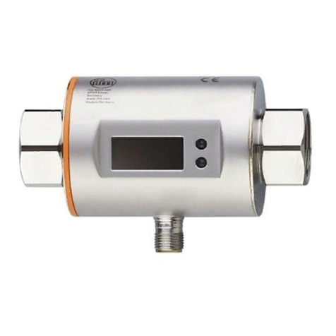
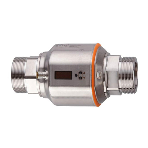
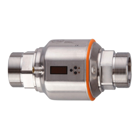
●SM6000 flow meter for monitoring and display of the flow temperature and the cooling water
volumetric flow quantity� The setting of 2 switch points allows the detection of overflow (leakage / burst
pipes / worn caps).
●String regulator valve to regulate the volumetric flow quantity
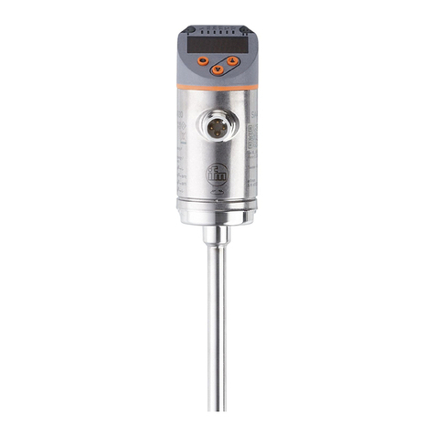
●TA2405 temperature sensor to monitor the return temperature
The fluid monitoring system transfers the process values to an IO-Link master via the IO-Link interface�
5.2 IO-Link master
The IO-Link master serves as a gateway for the process data of the connected sensors� The IO-Link
master enables setting of the parameters of the connected sensors via the LR DEVICE parameter setting
software�

Fluid monitoring system - Application package
6
21
ZZ0600
5LR DEVICE
+
3
4
Fig� 1: Overview application package
1: Power supply
2: AL13nn IO-Link master
3: SM6000 flow meter
4: TA2405 temperature sensor
5: ifm memory stick with LR DEVICE parameter setting software
6 Installation
►Disconnect the power of the machine before installation�
►Adhere to the instructions enclosed to the individual devices�
6.1 Fluid monitoring system
►Mount the fluid monitoring system in the cooling water process�
► Adhere to the flow direction during installation (black arrow mark).
6.2 IO-Link master
►Fix the IO-Link master to a flat installation surface�

7
Fluid monitoring system - Application package
UK
►Use 2 mounting screws and washers of size M5 for fixing�Tightening torque: 1�8 Nm�
6.3 Power supply
►Integrate the power supply into the control cabinet� The following has to be observed:
– Suited for DIN rails according to EN 60715 with a height of 7�5 or 15 mm�
– Align the input terminals downwards�
– In case of continuous full load adhere to the following installation distances:
Left / right: 5 mm (15 mm for adjacent heat sources)
Top: 40 mm, bottom 20 mm from the device�
The device is rated for convection cooling�
►Do not impede the air circulation� Adhere to installation distances�
7 Electrical connection
The unit must be connected by a qualified electrician�
►Observe the national and international regulations for the installation of electrical equipment�
►Adhere to the instructions enclosed to the individual devices�
►Disconnect power�
1� Connect the sensors of the fluid monitoring systems to the IO-Link master�
2� Connect the IO-Link master to the secondary side of the power supply�
3� Connect the IO-Link master to the PC via the IoT interface�
4� Connect the primary side of the power supply to the supply voltage�
4.1 Pin assignment of the IO-Link master
AL1300 / AL1320 / AL1330 / AL1340
21
43
65
87
1: Fieldbus (optional)
2: Fieldbus (optional)
3: Power supply
4: IoT interface to the PC with LR DEVICE
5: SM6000
6: TA2405
7: Not connected
8: Not connected

Fluid monitoring system - Application package
8
AL1350
21
3
54
76
1: IoT interface to the PC with LR DEVICE
2: Not connected
3: Power supply
4: SM6000
5: TA2405
6: Not connected
7: Not connected
5 Set-up
When the operating voltage has been applied, the components of the application package function
according to the factory settings. The LEDs show the status of the devices and interfaces (→ Instructions
of the individual components).
5.1 Install LR DEVICE
LR DEVICE allows the parameter setting of the IO-Link master and the connected sensors�
►Start the PC�
►Log in with administrator rights�
► Install the LR DEVICE parameter setting software from the ifm memory stick to PC (→ Software
manual LR DEVICE).
►Start LR DEVICE�
> The user interface of the LR DEVICE appears�
5.2 Configure the interface to the IO-Link master
For parameter setting, the IoT interface of the IO-Link master and the Ethernet interface of the PC must
be configured for the same subnet:
►Click on the symbol [
IO-LINK
] to scan the network for available devices�
> LR DEVICE finds the connected IO-Link master�
►In the [ONLINE] area: Click on the IO-Link master found�
> The detail window shows the IP settings of the IoT interface of the IO-Link master�
►Adapt the IP settings of the IoT interface to the IP settings of the Ethernet interface of the PC�

9
Fluid monitoring system - Application package
UK
Example:
Parameter Ethernet interface (PC) IoT interface (IO-Link master)
IP address 192�168�0�50 192�168�0�1
Subnet mask 255�255�255�0 255�255�255�0
Gateway address 0�0�0�0 0�0�0�0
►Click on the symbol [
IO-LINK
] to write the changed values to the IO-Link master�
> LR DEVICE reads the unit with the changed values once again�
> LR DEVICE has access to the parameters of the connected sensors (→ 6 Parameter setting)�
6 Parameter setting
The parameters can be set before installation or during operation via the IO-Link interface�
If you change parameters during operation, this will influence the function of the plant�
►Ensure that there will be no malfunctions in your plant�
During parameter setting the sensors remain in the operating mode� They continue to monitor with the
existing parameter until the parameter setting has been completed�
The sensors' IODD at www�ifm�com contains a complete list of adjustable parameters�
6.1 Change limit values and switch points
Adjust the limit values and switch points of the sensors:
In LR DEVICE:
►Click on the symbol [
IO-LINK
] to scan the network for available devices�
> LR DEVICE finds the connected IO-Link master�
►In the [ONLINE] area: Click on the IO-Link master found�
> LR DEVICE shows the sensors connected to the ports�
► Click on Port ([P1: SM6000] or [P2: TA2405]).
> Adjustable parameters of the connected sensor are displayed�
►Change limit values and switch points�
►Click on the symbol [
IO-LINK
] to write the changed parameter values to the sensor�
> The sensor functions with the changed parameter values�

Fluid monitoring system - Application package
10
7 Operation
7.1 Monitor the process data
In normal operation, LR DEVICE can display the process data of the application package graphically�
In LR DEVICE:
►Click on the symbol [
IO-LINK
] to scan the network for available devices�
> LR DEVICE finds the connected IO-Link master�
►In the [ONLINE] area: Click on the IO-Link master found�
►Click on the symbol [Cockpit]�
> The current state and the chronological curve of the process values are displayed�
Other manuals for ZZ0600
1
Table of contents
Other IFM Measuring Instrument manuals
Popular Measuring Instrument manuals by other brands

Velleman
Velleman EMDIN03 user manual

Endress+Hauser
Endress+Hauser Flowphant T DTT31 technical information

KROHNE
KROHNE IFC 090 Supplementary installation & operation instructions

Fluke
Fluke 323 Calibration manual

Fluke
Fluke 85RF II instruction sheet

Calculated Industries
Calculated Industries Scale Master Pro XE 6135 user guide