MiFleet +Vision User manual

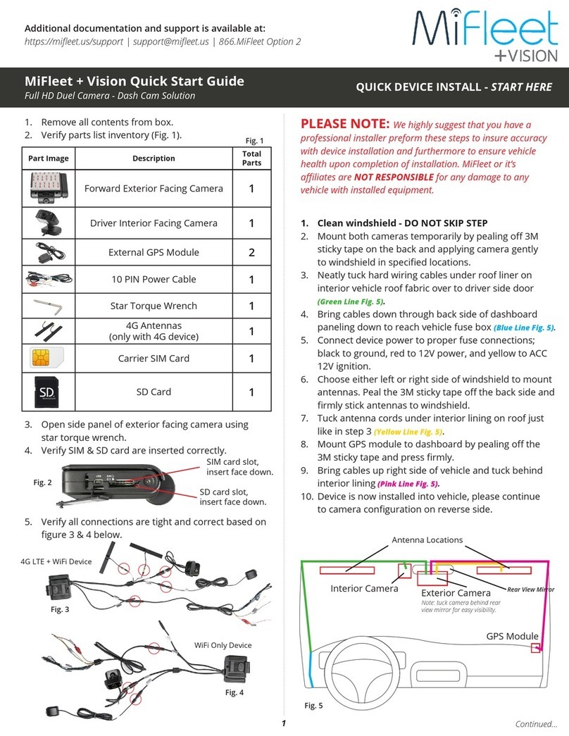
MiFleet Dash Cam Hardware Install Guide
For more information, please visit our website www.MiFleet.us/support

02For more information, please visit our website www.MiFleet.us/support
Item Name Application Total
Parts
Front facing
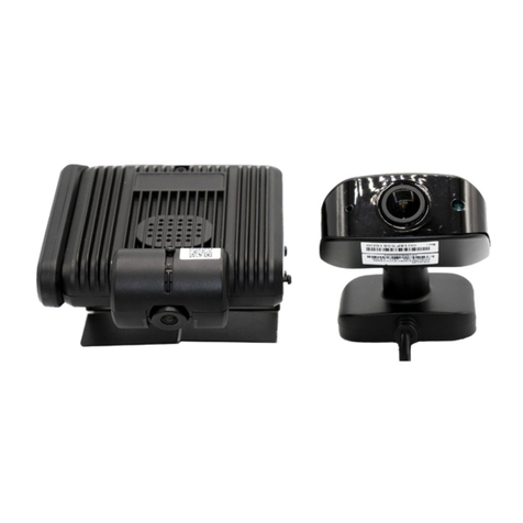
camera Camera faces exterior trac 1 pcs
Driver facing
camera
Camera faces interior of vehicle,
generally pointed at driver 1 pcs
4G Antenna
(Only available for
LTE device)
Communication antenna to
amplify signal and GPS function 2 pcs
External GPS
Antenna
Used for obtaining GPS location
of vehicle at all times 1 pcs
10 PIN Power
Cable
Power input cable with PB
alarm input 1 pcs
2 Lens Wipes To clean your camera lenses 2 pcs
Wrench Used to open or close SIM door 1 pcs
LENS CLEANING
W I P E
Items Included in the Box

03
Additional Optional Tools for Install
(these items are not included)
Before install, we suggest you prepare the following accessories and tools to assist in
an easier more professional install.
(Please consult a professional installer before using any of these additional optional tools on your vehicle.)
For more information, please visit our website www.MiFleet.us/support
Item Name Application Total
Parts
Phillips
Screwdriver
Remove the screw of the safety
cover and x the ignition
signal cable
1 pcs
Seesaw For removing vehicle panels such
as A-pillars 1 pcs
Zip Ties Used for stopping thread 10 pcs
Dry Cloth Used to clean the
mounting spots 1 pcs
Smart Phone
or Tablet
Used to install software for video
preview and conguration 1 pcs
Marker Used for Front facing installation 1 pcs
Wire Strippers For shearing and stripping cables
(for vehicles without OBDII port) 1 pcs
Electrical Tape Used for dressing exposed wire
ends 1 pcs

04
Helpful Tips Before Install
NOTE: We highly suggest that you have a professional camera installer preform these steps to
insure accuracy with device installation. Furthermore, to insure vehicle health upon completion
of installation.
1. Please read the packing list section carefully and check when unpacking.
2. Please read the tool list section carefully and bring your own tools before installation.
3. Observe the vehicle environment before installation.
Important instructions to follow when installing:
-Installationlocationdoesnotaectthedriver’svision.
- The location of front facing camera must be installed within the working range of the wiper.
-Thelocationofdriverfacingcamerashouldnotaecttherearviewmirror.
4. The appropriate installation location should be selected according to the vehicle
environment. This document is for reference only.
5. The appropriate powering method should be selected according to the vehicle
environment. This document is for reference only.
6. If there is a problem with the installation of a special vehicle, please contact your local
installer for additional assistance.
7. To make sure your camera connections are properly connected, please reference gure 1.
Fig. 1
NOT USED
FRONT FACING CAMERA
(Road Facing)
DRIVER FACING CAMERA
(Internal Facing)
GPS ANTENNA
4G ANTENNAS
NOT USED
IGNITION ON - Yellow Wire
GROUND - Black Wire
POWER IN CONSTANT 12V - Red Wire
For more information, please visit our website www.MiFleet.us/support

05
2. If not already done, please connect the power in, GPS antenna, and IPC to the camera unit as shown in gure 1.
4G Antennas
GPS
Antenna
Driver Facing
Camera
Front Facing
Camera
Dash Cam Install Instructions
1. Select the camera mounting location
NOTE: Front facing camera is recommended to
be mounted right behind the rear view mirror. The
driver facing camera can be mounted on either side
of the rear view mirror. The mounting place for 4G
antenna and GPS antenna are shown on in image
on right. Adjust camera so the front facing camera
does not block the view of the driver. Driver facing
camera is a wide angle camera so the camera
does not need to face the driver directly. Rear view
mirrors and sun visors should not be aected after
installation of the driver facing camera.
Fig. 1
NOT USED
FRONT FACING CAMERA
(Road Facing)
DRIVER FACING CAMERA
(Internal Facing)
GPS ANTENNA
4G ANTENNAS
NOT USED
IGNITION ON - Yellow Wire
GROUND - Black Wire
POWER IN CONSTANT 12V - Red Wire
Img. 1 Mounting Locations
For more information, please visit our website www.MiFleet.us/support

06
5. Remove panel (shown in image 5) and tuck cables up in roof interior lining of vehicle and follow the direction
show in images 4 and 6. Extend the cables down from the A-pillar to the fuse box or power supply as follows.
3. Properly clean the camera mounting location on the windshield interior of the vehicle with cloth to make sure
the glass is clean and dry as shown in image 2.
4. Remove 3M backing and stick front facing and driver facing cameras to windshield in desired position as show
in image 3.
NOTE: Images above show how the front facing camera should be mounted. If surface is not cleaned properly before mounting, device will have issues
sticking and you may experience device falling from glass.
Img. 2 Img. 3
Img. 4 Wire Locations Img. 5 Img. 6
6. Zip tie (if available) camera cables to existing vehicle cables already hidden under paneling to ensure a proper
and long lasting install. Once complete, reinstall panel.
For more information, please visit our website www.MiFleet.us/support

07
7. Feed cables behind dashboard down to the foot pedals and fuse box in driver location. Once cables are visible
you have completed this step.
8. Locate the power (red), ground (black), and ACC ignition (yellow) cables after running wires down to fuse box as
shown in image 5.
9. Connect ACC ignition (yellow), power (red), and ground (black) cables to the corresponding port or cables in the
fuse box as shown in image 6.
Img. 5 Img. 6
10. Adjust camera angle by loosing screw and rotating camera lens up and down. Once in desired location, tighten
screw to hold position shown in images 7 & 8.
Img. 7 Img. 8
For more information, please visit our website www.MiFleet.us/support

11. Plug the 4G antennas and GPS antenna into existing camera cabling (this step should already be done.)
12. Remove 3M backing and paste the 4G antennas on windshield as shown in image 9.
13. Make sure when mounting the two antennas are separated by at least 5 cm to insure proper connectivity.
08
14. Repeat steps 4 and 5 (shown in images 11, 12, and 13) by tucking remaining GPS antenna cable under vehicle
roof liner on passenger side of vehicle. Remove side panel, zip tie antenna cable to existing cables, and replace
side panel.
15. Remove 3M backing and rmly stick GPS antenna to dashboard as shown in image 10.
Install Steps for 4G Antennas (LTE ONLY)
Img. 9 Img. 10
Img. 11 Img. 12 Img. 13
For more information, please visit our website www.MiFleet.us/support

LED indicator
There is only one LED status indicator on the MiFleet + Vision base. The working status of device can be
reected by the lighting.
• No light on device means the device is not powered on.
• Steady red light means the device is powered on and booting up or in sleep mode.
• Red light ashing once per second means the device is in the process of booting up or completed but
containing antenna fault. Antenna fault includes no GPS, no WiFi, no SD card, and / or video loss.
• Steady green light means device is working normally.
Basic Troubleshooting Steps
09For more information, please visit our website www.MiFleet.us/support
Other manuals for +Vision
4
Table of contents
Other MiFleet Dashcam manuals
