MiiVii Apex Xavier User manual
3/5/23, 3:44 PM
产品文档 : EN_Apex Xavier Manual
doc.miivii.com/EN_Apex-Xavier-Manual_9732239.html
1/45
Notice
Please read manual carefully before install, operate, or transport device.
Ensure that the correct power range is being used before powering the device.
Avoid hot plugging.
To properly turn off the power, please shut down the Ubuntu system first, and then cut off the power.
Due to the particularity of the Ubuntu system, on the Nvidia developer kit, if the power is turned off
when the startup is not completed, there will be a 0.03% probability of abnormality, which will cause
the device to fail to start. Due to the use of the Ubuntu system, the same problem also exists on the
Miivii device.
Do not use cables or connectors other than described in this manual.
Do not use MiiVii device near strong magnetic fields.
Backup your data before transportation or MiiVii device is idle.
Recommend to transport MiiVii device in its original packaging.
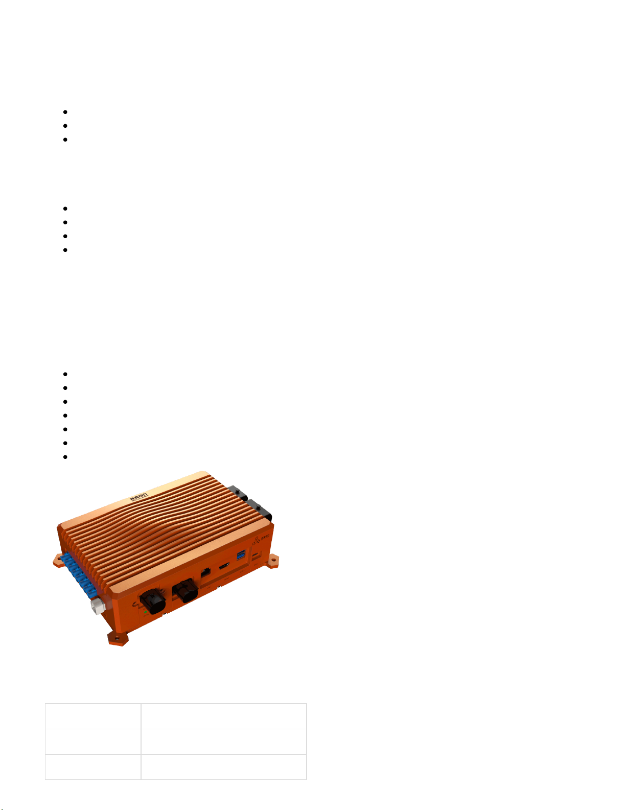
Brief
MiiVii Apex Xavier is an embedded computing platform based on NVIDIA Jetson AGX Xavier. With
waterproof and shockproof connectors and powerful computer vision processing capability, Apex Xaiver is
designed for autonomous machines, especially for outdoor environment use. Apex Xavier offers
synchronization feature, which is essential for multi-sensor fusion. In addition, a variety of computer vision
algorithm acceleration SDK are provided on Apex Xavier platform.
Included in the Box
Apex Xavier×1
Power Supply×1
Power cable×1
I/O Cable Assemblies×1
4G Antenna×2
WiFi Antenna×2
Quick Start×1
Specifications
Processor
Processor NVIDIA Jetson AGX Xavier
CPU 8-core ARM v8.2 64-bit CPU
GPU 512-core Volta GPU

3/5/23, 3:44 PM
产品文档 : EN_Apex Xavier Manual
doc.miivii.com/EN_Apex-Xavier-Manual_9732239.html
2/45
Processor NVIDIA Jetson AGX Xavier
Memory 32GB 256-Bit LPDDR44
DL Accelerator 2×NV DLA Engines
Storage 32GB eMMC 5.1
I/O
Interface Quantity Note
Network Ethernet 1×8pin Waterproof Gigabit
Ethernet port
1×RJ45 Gigabit Network port
Alternative RJ45 and waterproof port
WIFI 1 2.4G/5.8G 300Mbps
Camera Camera 8×CSI 1 Lane GMSL FAKRA
Z TYPE
9V
Transmission distance up to 15
meters
Video output Video out 1×GMSL FAKRA Z TYPE
HDMI 1×HDMI 2.0 TYPE A
USB USB 2×USB 3.1 TYPE A
1×Micro USB
USB 5V, 1A
Micro USB 5V, 0.5A
I/O GPIO 5xGPIO IN 0-12V, OUT 3.3V
CAN 2 DB9 Terminal
With CAN chip
Terminal resistor 120Ω
UART 1xDebug
2xTTL/RS232
2xRS232/422/485
DB9 Terminal
TTL 3.3V
SPI 1 3.3V
I2C 1 3.3V
I2S 1 3.3V
Sync I/O 1xSYNC_IN
2xSYNC_OUT
2xSYNC_PPS
DB9 Terminal
SYNC_IN 0-12V, SYNC_OUT 3.3V,
SYNC_PPS 3.3V
User
Expansion
TF 1xTF Slot MicroSD card supported
M.2 1×M.2 M Key
1×M.2 B Key
2280 SIZE NVME SSD 4G LTE
Function
Key
Power KEY 1 Button
3/5/23, 3:44 PM
产品文档 : EN_Apex Xavier Manual
doc.miivii.com/EN_Apex-Xavier-Manual_9732239.html
3/45
Reset KEY 1 Button
Recovery
KEY
1 Button
Power Supply
Power Supply Spec
Input Type DC
Input Voltage Wide input 12-50V DC
Typical consumption 30W
Mechanical
Mechanical Spec
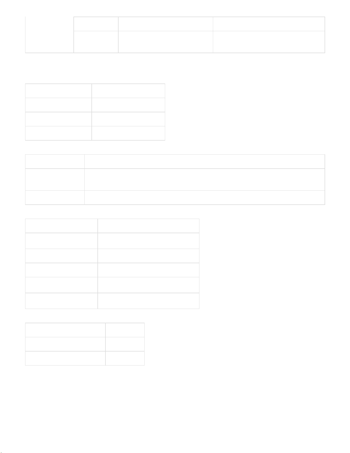
Dimensions
(W×H×D)
245mm×68mm×172mm (I/O ports and mounting holes included)
213mm×68mm×143mm (I/O ports and mounting holes excluded)
Weight 2.2Kg
Environmental
Environmental Spec
Operating Temperature -20℃-70℃, 0.2~0.3m/s air flow5
Storage Temperature -25℃-80℃
Storage Humidity 10%-90% non-condensing
Vibration 5gn,10Hz~150Hz,3 Axis6
Protection IP4X7
Certification
Certification Status
CE Passed
CCC, FCC, RoHS, SRRC Processing
[4] Jetson AGX Xavier increase of DRAM memory size from 16GB to 32GB.
[5] According to GB/T 2423-2008 Working frequency is subject to change after temperature reaches 60℃
[6] According to GB/T 2423.10-2008
[7] Professional I/O ports are IP67-rated. To achieve IP67 rating of Apex Xavier, please contact MiiVii for a
second version of case design.
Install Dimension
Dimensions and mounting hole position as below:
3/5/23, 3:44 PM
产品文档 : EN_Apex Xavier Manual
doc.miivii.com/EN_Apex-Xavier-Manual_9732239.html
4/45
Up view(Unit:mm)
Left view(Unit:mm)
Service and Support
Support
MiiVii is glad to help you with any questions you may have about our product, or about the use of the
technology for your application. The fastest way is sending us an email: [email protected]. Or you could
visit our developer forum: http://forum.miivii.com for solutions.
Warranties
Warranty period: One year from the date of delivery.
Warranty content: MiiVii warrants the product manufactured by us to be free from defects in material and
workmanship during warranty period. Please contact [email protected] for return material authorization
(RMA) prior to returning any items for repair or exchange. The product must be returned in its original
packaging to prevent damage during shipping. Before returning any product for repair, it is recommended to
back up your data and delete any confidential or personal data.
Interfaces
Interfaces
Front panel

3/5/23, 3:44 PM
产品文档 : EN_Apex Xavier Manual
doc.miivii.com/EN_Apex-Xavier-Manual_9732239.html
5/45
Figure Apex Xavier Front view
Interface Name Description
DC IN Power interface Power input voltage: 12-50V
STATUS_LED System status
indicator
System on: solid blue System off: solid red
POWER_LED Carrier board status
indicator
Carrier board power on: solid yellow Carrier board system
on: solid white Carrier board system error: solid red
LAN(Waterproof) Gigabit Ethernet Only LAN port one could work at the same time
LAN(RJ45) Gigabit Ethernet Only LAN port one could work at the same time
HDMI HDMI Port HDMI 2.0
USB×2 USB3.1Port USB 3.1 is backwards compatible with USB 3.0 and USB
2.0
Micro USB Micro USB Port Support USB OTG
LAN(Waterproof) Pin:
3/5/23, 3:44 PM
产品文档 : EN_Apex Xavier Manual
doc.miivii.com/EN_Apex-Xavier-Manual_9732239.html
6/45
Figure LAN(Waterproof) Pin
Circuit Description
1 MDI0+
2 MDI0-
3 MDI1+
4 MDI1-
5 MDI2+
6 MDI2-
7 MDI3+
8 MDI3-
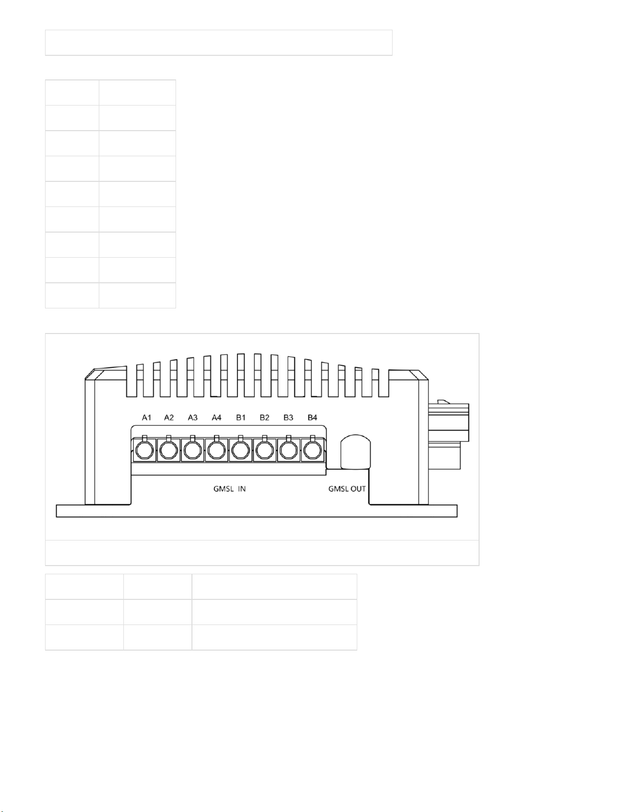
Left Panel
Figure Apex Xavier Left Panel
Interface Name Description
GMSL IN GMSL in Support 8 GMSL cameras(9v)
GMSL OUT GMSL out Support 1 GMSL display
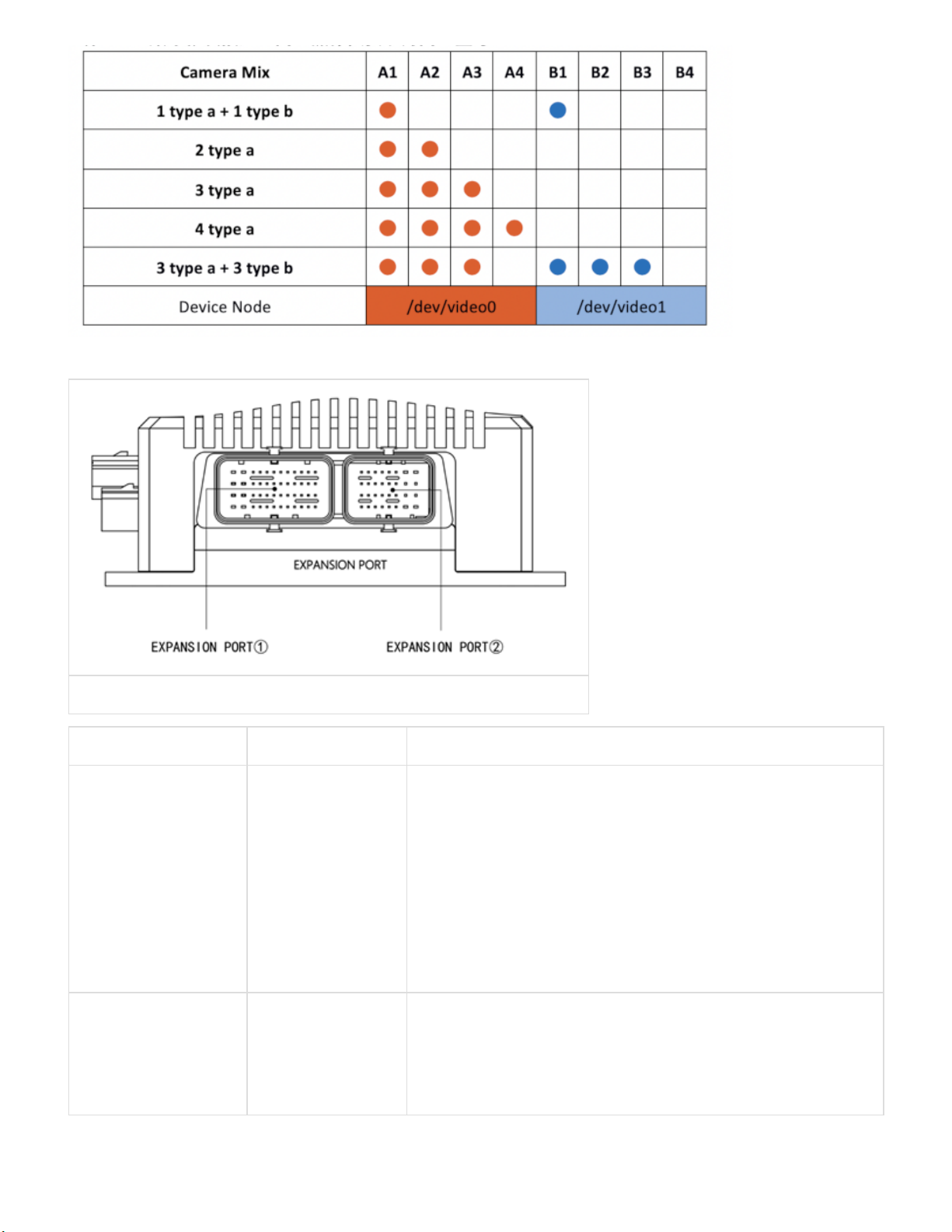
There is no restriction between two groups. When you connect cameras to a specific camera group, you must
attach the cameras in sequential order: A1 to A4 or B1 to B4. Homogeneous camera types are required per
camera group.
3/5/23, 3:44 PM
产品文档 : EN_Apex Xavier Manual
doc.miivii.com/EN_Apex-Xavier-Manual_9732239.html
7/45
Right Panel
Figure Apex Xavier Right Panel
Interface Name Description
EXPANSION
PORT①
I/O Expansion
Port 1
1×DEBUG
2×TTL/232(TTL 3.3V)
2×232/422/485
2 × CAN(With CAN chip, terminal resistor 120Ω)
2×SYNC_PPS(3.3V)
1× SYNC_OUT(3.3V)
1×SYNC_IN(Logic High 1V-12V, Logic Low 0V-0.8V)
1 × POWER_ONKEY
1×FORCE_RECOVERY
1×RESET
EXPANSION
PORT②
I/O Expansion
Port 2
1×IIS(3.3V)
1×IIC(3.3V)
1×SPI(3.3V)
5×GPIO(For IN: Logic High 1V-12V, Logic Low 0V-0.8V.
For OUT:3.3V)
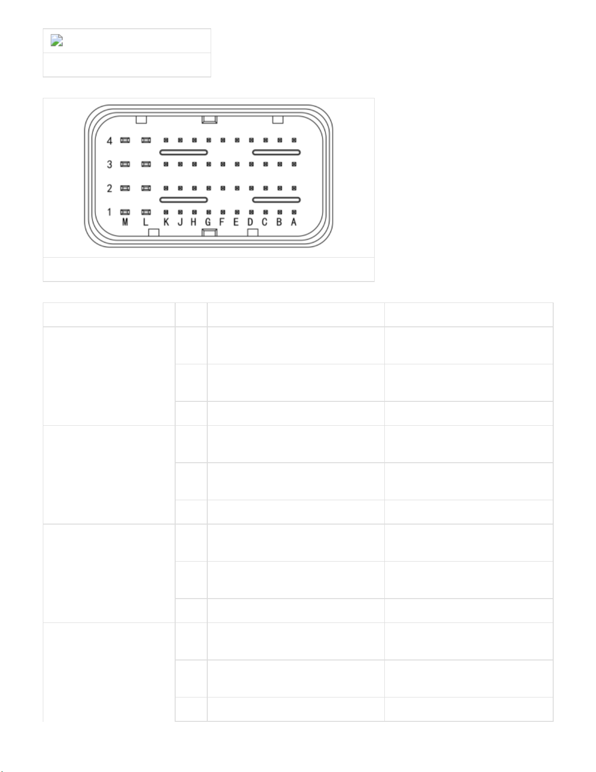
I/O Expansion Port Pin Definitions
There are two I/O expansion ports at the right panel of Apex Xavier, as EXPANSION PORT ① and
EXPANSION PORT ②:
3/5/23, 3:44 PM
产品文档 : EN_Apex Xavier Manual
doc.miivii.com/EN_Apex-Xavier-Manual_9732239.html
8/45
apex_expansion_overall.png
Figure I/O Expansion Ports
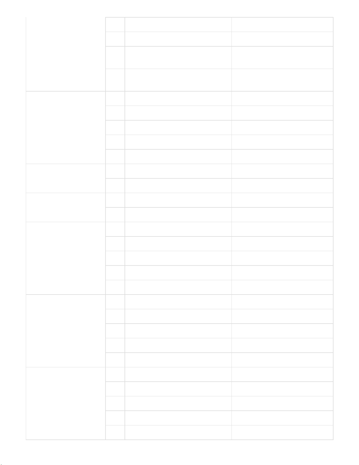
EXPANSION PORT ① Pin Assignments
Figure EXPANSION PORT ①
Port Name Pin Definition Description
UART(TTL/232)A
DEBUG8
G1 UART(TTL/232)A_RX UART(TTL/232)A: TTL-
RX/232-RX
H1 UART(TTL/232)A_TX UART(TTL/232)A: TTL-
TX/232-TX
J1 GND Ground
UART(TTL/232)B D1 UART(TTL/232)B_RX UART(TTL/232)B: TTL-
RX/232-RX
E1 UART(TTL/232)B_TX UART(TTL/232)B: TTL-
TX/232-TX
F1 GND Ground
UART(TTL/232)C B2 UART(TTL/232)C_RX UART(TTL/232)C: TTL-
RX/232-RX
A2 UART(TTL/232)C_TX UART(TTL/232)C: TTL-
TX/232-TX
A3 GND Ground
UART(232/422/485)A K1 UART(232_RX/485_A/422_T+)A UART(232/422/485)A:
232_RX/485_A/422_T+
L1 UART(232_TX/485_B/422_T-)A UART(232/422/485)A:
232_TX/485_B/422_T-
M1 UART(422_R+)A UART(232/422/485)A: 422_R+
3/5/23, 3:44 PM
产品文档 : EN_Apex Xavier Manual
doc.miivii.com/EN_Apex-Xavier-Manual_9732239.html
9/45
M2 UART(422_R-)A UART(232/422/485)A: 422_R-
L2 GND Ground
UART(232/422/485)B G2 UART(232_RX/485_A/422_T+)B UART(232/422/485)B:
232_RX/485_A/422_T+
F2 UART(232_TX/485_B/422_T-)B UART(232/422/485)B:
232_TX/485_B/422_T-
E2 UART(422_R+)B UART(232/422/485)B: 422-R+
D2 UART(422_R-)B UART(232/422/485)B: 422-R-
C2 GND Ground
CAN_A B3 CAN_A_L CAN_A Low
C3 CAN_A_H CAN_A High
CAN_B D3 CAN_B_L CAN_B Low
E3 CAN_B_H CAN_B High
PPS_A A1 PPS_A_RX PPS_A: TTL-RX/232-RX
B1 PPS_A_TX PPS_A: TTL-TX/232-TX
C1 GND Ground
F3 PPS_A_SYNC PPS_A_SYNC Pulse signal
G3 GND Ground
PPS_B K2 PPS_B_RX PPS_B: TTL-RX/232-RX
J2 PPS_B_TX PPS_B: TTL-TX/232-TX
H2 GND Ground
H3 PPS_B_SYNC PPS_B_SYNC Pulse signal
J3 GND Ground
SYNC_IO K3 SYNC_IN Sync in Signal
L3 GND Ground
M3 SYNC_OUT Sync out Signal
M4 GND Ground
K4 GND Ground
RESET J4 RESET Reset
RECOVERY G4 FORCE_RECOVERY Recovery

3/5/23, 3:44 PM
产品文档 : EN_Apex Xavier Manual
doc.miivii.com/EN_Apex-Xavier-Manual_9732239.html
10/45
POWER E4 POWER_ONKEY Power
GND H4 GND Ground
F4
D4
[8] UART(TTL/232)A is a DEBUG port, all TTL is 3.3V
If you want to use GPS Sync function, please refer to the following instruction:
Connect GPS NMEA Serial port to UART(TTL/232)B port of Apex Xavier(Baud 9600), device node is
/dev/ttyUART_TTL_232_B
Connect GPS PPS Port to SYNC_IO PIN1of Apex Xavier, device node is /dev/miivii-sync-in-a
These two nodes above is occupied while GPS Sync function is available.
EXPANSION PORT ② Pin Assignment
Figure EXPANSION PORT②
Port Name Pin Definition Description
SPI Port A4 SPI_SCK SPI continuous serial clock
B4 SPI_MISO SPI master input slave output, or master in slave out
C4 SPI_MOSI SPI SPI master output slave input, or master out slave in
D4 SPI_CS0 SPI slave select
E4 GND Ground
IIS Port F4 IIS_MCLK05 IIS master clock
G4 IIS_PWM01 IIS interrupt
H4 IIS_SDIN IIS serial data in
H3 IIS_SDOUT IIS serial data out
G3 IIS_FS IIS frame sync
F3 IIS_CLK IIS continuous serial clock
3/5/23, 3:44 PM
产品文档 : EN_Apex Xavier Manual
doc.miivii.com/EN_Apex-Xavier-Manual_9732239.html
11/45
E3 GND Ground
IIC Port D3 IIC_CLK IIC serial clock
C3 IIC_DAT IIC serial data
B3 GND Ground
Audio Port A3 IN1P MIC Signal
A2 AUD_HPOR Right channel signal
B2 AUD_HPOL Left channel signal
C2 GND Ground
GPIO Ports D2 GPIO_A1 GPIO_IN
F2 GPIO_B13
H2 GPIO_C24 GPIO_OUT
G1 GPIO_D26
E1 GPIO_E33
GND E2 GND Ground
G2
H1
F1
A1
5V B1 5V 5V
GPIO Pin Assignment
Port Name Pin Number GPIO Default Setting GPIO Export Value
GPIO D2 GPIO_A GPIO_IN 339
F2 GPIO_B 433
H2 GPIO_C GPIO_OUT 387
G1 GPIO_D 390
E1 GPIO_E 413
Rear Panel

3/5/23, 3:44 PM
产品文档 : EN_Apex Xavier Manual
doc.miivii.com/EN_Apex-Xavier-Manual_9732239.html
12/45
Figure Apex Xavier Rear Panel
Interface Name Description
①② 2.4G/5.8G WiFi Antenna connector Connect to 2.4G/5.8G WiFiantenna
③④ 4G Antenna connector Connect to 4G antenna
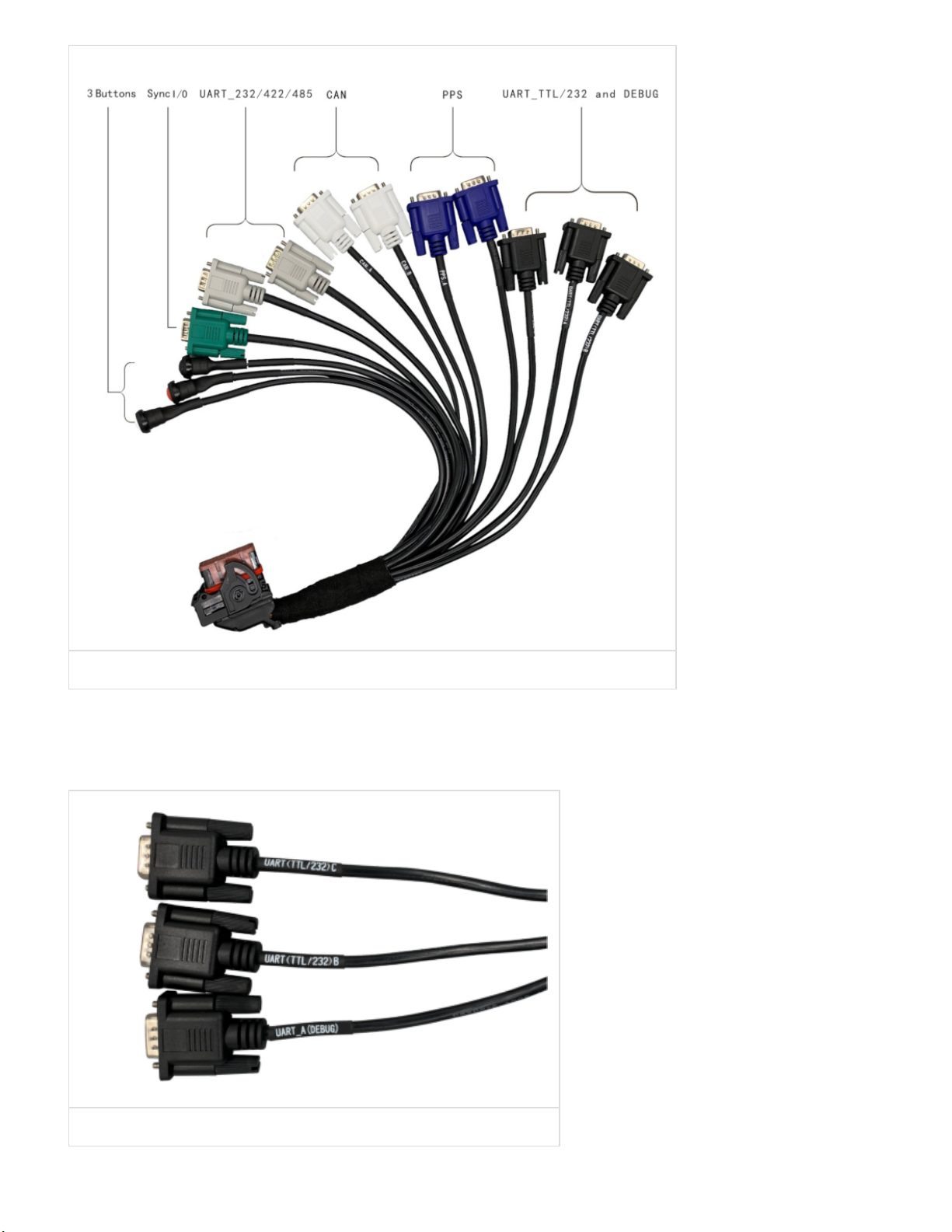
I/O Cable
Apex Xavier provides one I/O cable with 10 DB-9(DE-9) connectors and 3 buttons, as an extension of
EXPANSION PORT ①
Number Port Quantity Details
1 UART_TTL/232 3 Black DB9 connector
2 UART_232/422/485 2 Gray DB9 connector
3 CAN 2 White DB9 connector
4 PPS 2 Dark Blue DB9 connector
5 Sync I/O 2 Share one dark green DB9 connector
6 Button 3 1 RESET Button(White) 1 RECOVERY Button(Black)
1 POWER_ONKEY Button(Red)
3/5/23, 3:44 PM
产品文档 : EN_Apex Xavier Manual
doc.miivii.com/EN_Apex-Xavier-Manual_9732239.html
13/45
Figure I/O Cable
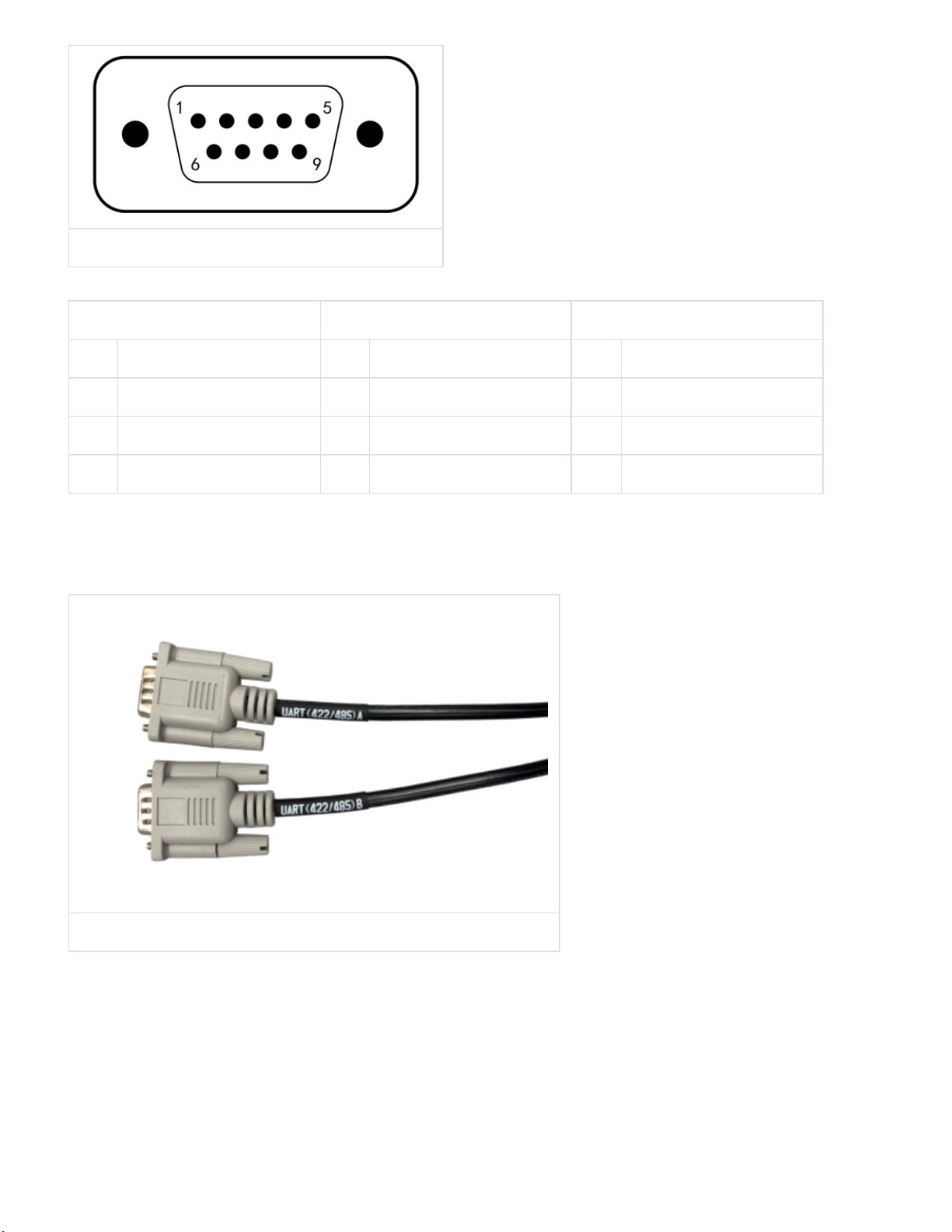
UART(TTL/232)Ports and Pin Assignments
Apex Xavier provides 3 TTL/RS232 ports: UART(TTL/232)A, UART(TTL/232)B and UART(TTL/232)C.
UART(TTL/232)A is for debugging use. Black DB9 connectors from I/O cable are shown as below:
Figure UART(TTL/232) Cable and Connectors
3 UART(TTL/232) DP9 connectors pin assignments:
3/5/23, 3:44 PM
产品文档 : EN_Apex Xavier Manual
doc.miivii.com/EN_Apex-Xavier-Manual_9732239.html
14/45
Figure UART(TTL/232) Pin
UART(TTL/232)A UART(TTL/232)B UART(TTL/232)C
Pin Signal Pin Signal Pin Signal
2 UART(TTL/232)A_RX 2 UART(TTL/232)B_RX 2 UART(TTL/232)C_RX
3 UART(TTL/232)A_TX 3 UART(TTL/232)B_TX 3 UART(TTL/232)C_TX
5 GND 5 GND 5 GND
UART(232/422/485) Ports and Pin Assignments
Apex Xavier provides 2 RS232/RS485/RS422ports: UART(232/485/422)A and UART(232/485/422)B. Gray
DB9 connectors from I/O cable are shown as below:
Figure UART(422/485) Cable and Connectors
2 UART(232/422/485) DP9 connectors pin assignments:

3/5/23, 3:44 PM
产品文档 : EN_Apex Xavier Manual
doc.miivii.com/EN_Apex-Xavier-Manual_9732239.html
15/45
Figure UART(422/485) Pin
UART(232/422/485)A UART(232/422/485)B
Pin Signal Pin Signal
2 UART(232_RX/485_A/422_T+)A 2 UART(232_RX/485_A/422_T+)B
3 UART(232_TX/485_B/422_T-)A 3 UART(232_TX/485_B/422_T-)B
5 GND 5 GND
6 UART(422_R-)A 6 UART(422_R-)B
7 UART(422_R+)A 7 UART(422_R+)B
Relation of UART Port and device node as follow:
Pin UART Port Device Node
1 UART(TTL/232)A DEBUG
2 UART(TTL/232)B ttyUART_TTL_232_B
3 UART(TTL/232)C ttyUART_TTL_232_C
4 UART(232/422/485)A ttyUART_232_422_485_A
5 UART(232/422/485)B ttyUART_232_422_485_B
DIP switch for UART Ports:
Open Apex Xavier’s bottom cover, DIP switches are shown as below:

3/5/23, 3:44 PM
产品文档 : EN_Apex Xavier Manual
doc.miivii.com/EN_Apex-Xavier-Manual_9732239.html
16/45
Figure Apex Xavier DIP Switch
DIP switch settings are shown in the table below:
Figure DIP Switch Mapping
Number UART Port DIP Switch DIP Switch Settings
1 PPS_A UART1 1.For TTL signal: Switch to 'TTL’
2.For 232 signal: Switch to '232' (default)
2 PPS_B UART7
3 UART(TTL/232)A UART3
4 UART(TTL/232)B UART2

3/5/23, 3:44 PM
产品文档 : EN_Apex Xavier Manual
doc.miivii.com/EN_Apex-Xavier-Manual_9732239.html
17/45
5 UART(TTL/232)C UART9
6 UART(232/422/485)A UART5 1.For 232 signal: Switch to '232'
2.For 422/485 signal: Switch to '422/485'(default)
7 UART(232/422/485)B UART8
[9] Default switch for PPS ports and UART(TTL/232) ports is 232,default switch for UART(232/422/485)
ports is 485/422
CAN Ports and Pin Assignments
Apex Xavier provides 2 CAN ports: CAN_A and CAN_B. White DB9 connectors from I/O cable are shown
as below:
Figure CAN Cable and Connectors
2 CAN connectors pin assignments:
Figure CAN Pin
CAN_A CAN_B
Pin Signal Pin Signal
2 CAN_A_L 2 CAN_B_L
7 CAN_A_H 7 CAN_B_H
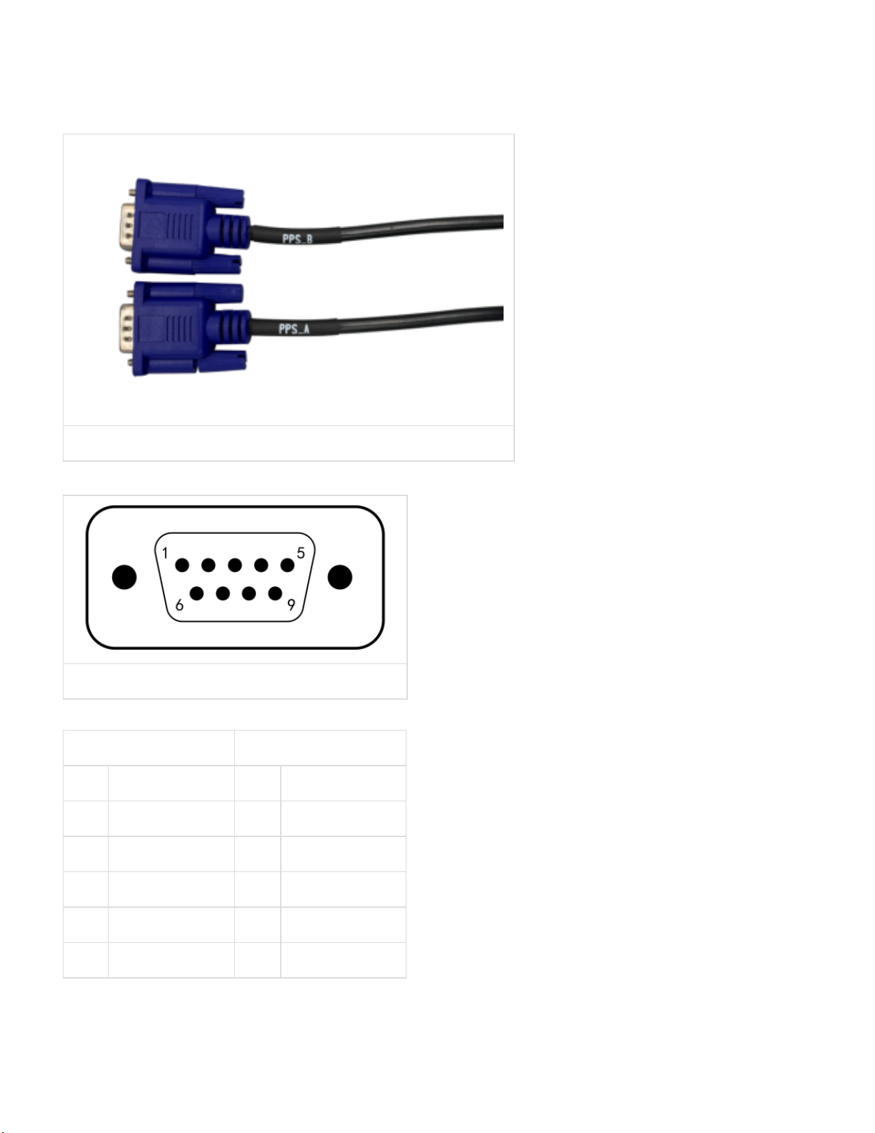
PPS Ports and Pin Assignments
3/5/23, 3:44 PM
产品文档 : EN_Apex Xavier Manual
doc.miivii.com/EN_Apex-Xavier-Manual_9732239.html
18/45
Apex Xavier provides 2 PPS ports: PPS_A(115200 Bd) and PPS_B(9600 Bd)10. The blue DB9 connectors
from I/O cable are shown as below:
[10] For the usage of PPS function, please refer to the "PPS Sync Method" section in "Synchronization
Function"
Figure PPS Cable and Connector
PPS_A(115200 Bd) and PPS_B(9600 Bd), Pin Assignments:
Figure PPS Pin
PPS_A PPS_B
Pin Signal Pin Signal
1 GND 1 GND
2 PPS_A_RX 2 PPS_B_RX
3 PPS_A_TX 3 PPS_B_TX
5 GND 5 GND
6 PPS_A_SYNC 6 PPS_B_SYNC
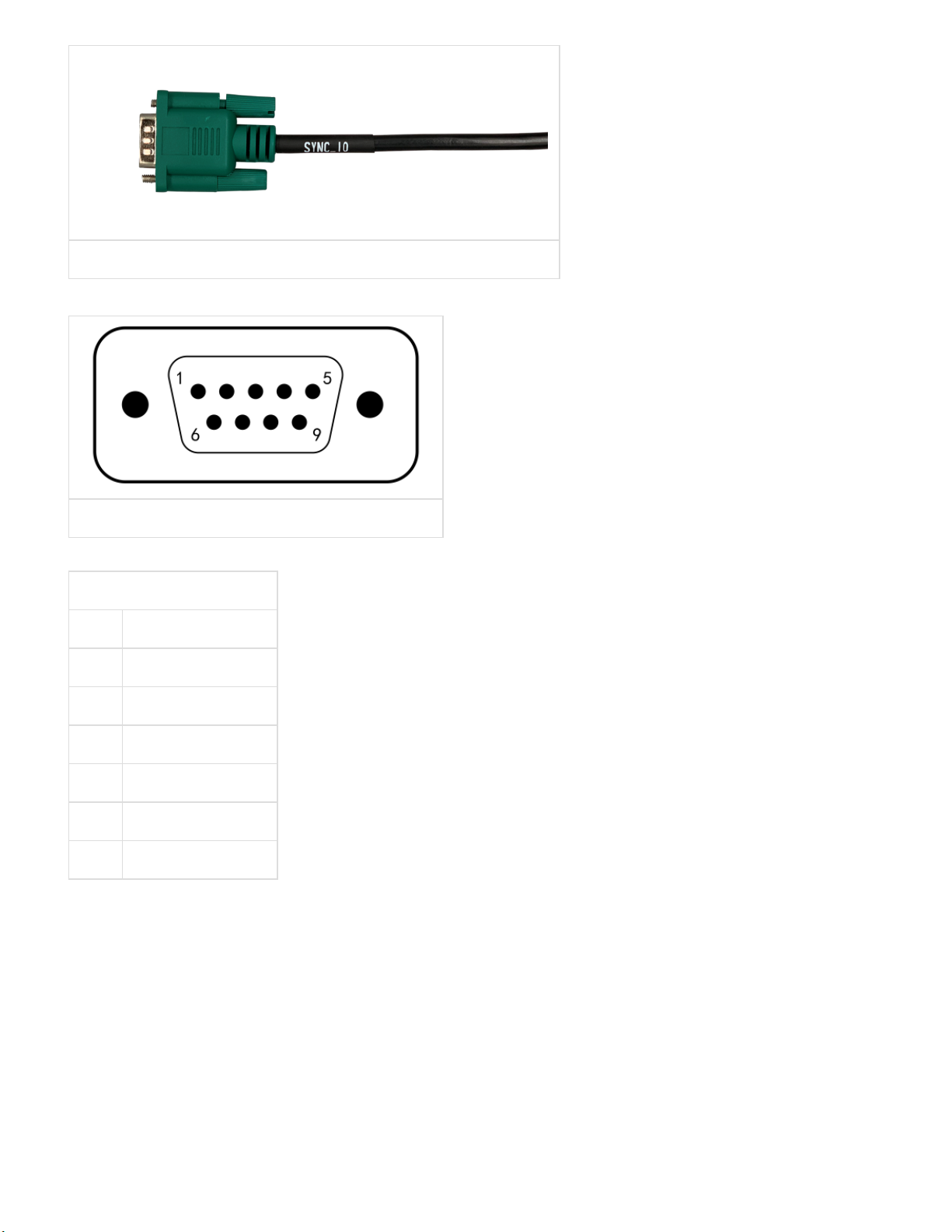
SYNC Ports and Pin Assignments
Apex Xavier provides 2 sync I/O ports: Sync_out and Sync_in11. They share the green DB9 connector from
I/O cable:
3/5/23, 3:44 PM
产品文档 : EN_Apex Xavier Manual
doc.miivii.com/EN_Apex-Xavier-Manual_9732239.html
19/45
Figure Sync IO Cable and Connector
SYNC_IO DB9 connector pin assignments::
Figure Sync IO Pin
Synchronization Signal
Pin Signal
1 SYNC_IN_A
2 SYNC_OUT_A
3 NC
6 GND
7 GND
8 GND
[11] For the usage of Sync_out and Sync_in function, please refer to the "Sync out Method" and "Sync in
Method" sections in "Synchronization Function"
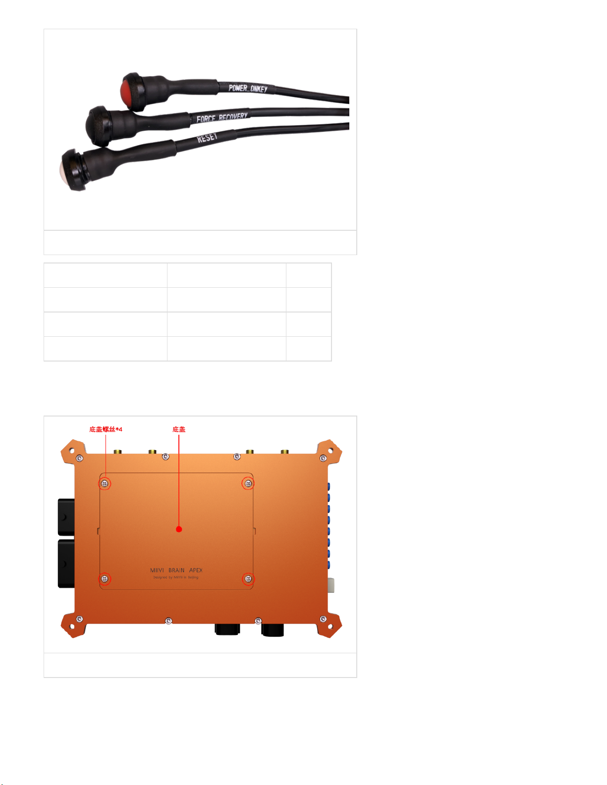
Buttons
Apex Xavier provides 3 buttons: RESET, POWER_ONKEY and FORCE_RECOVERY.
3/5/23, 3:44 PM
产品文档 : EN_Apex Xavier Manual
doc.miivii.com/EN_Apex-Xavier-Manual_9732239.html
20/45
Figure Function Buttons
Name Function Color
RESET Restart White
POWER_ONKEY Power on Red
FORCE_RECOVERY Enter Recovery mode Black
Expansion
Apex Xavier provides expansion sockets for SSD, 4G module, TF card and SIM card. Remove screws on
Apex Xavier’s bottom cover as shown in below:
Figure Apex Xavier Button Cover
Expansion sockets are shown as below. After installation, SSD card and 4G module need to be screwed.
Connect 4G antenna cable (attached to the board) to 4G module.
Table of contents
Popular Industrial PC manuals by other brands

VIA Technologies
VIA Technologies AMOS-3007 user manual

Siemens
Siemens SIMATIC IPC installation manual

IEI Technology
IEI Technology ECW-281B-945GSE user manual

EEPD
EEPD BoxPC-NUCV Device Reference Manual

Beckhoff
Beckhoff C6920 Installation and operating instructions

Valueline
Valueline VL PPC 6015 VW 10 user manual


