Aplex ACS-2702 User manual

ACS-2702
Intel Atom N2600 IP67 Waterproof Box PC
User Manual
Release Date Revision
Jul. 2015 V1.0
®2015 Aplex Technology, Inc. All Rights Reserved. Published in Taiwan
Aplex Technology, Inc.
15F-1, No.186, Jian Yi Road, Zhonghe District, New Taipei City 235, Taiwan

ACS-2702 User Manual 1
Revision History
Reversion
Date
Description
1.0
2015/07/08
Official Version

ACS-2702 User Manual 2
Warning!___________________________
Disclaimer
This information in this document is subject to change without notice. In no event shall
Aplex Technology Inc. be liable for damages of any kind, whether incidental or
consequential, arising from either the use or misuse of information in this document or in
any related materials.
Electric Shock Hazard –Do not operate the machine with its back cover removed.
There are dangerous high voltages inside.
This equipment generates, uses and can radiate radio frequency energy and if
not installed and used in accordance with the instructions manual, it may cause
interference to radio communications. It has been tested and found to comply with
the limits for a Class A computing device pursuant to FCC Rules, which are designed
to provide reasonable protection against such interference when operated in a
commercial environment. Operation of this equipment in a residential area is likely
to cause interference in which case the user at his own expense will be required to
take whatever measures may be required to correct the interference.

ACS-2702 User Manual 3
Packing List
Accessories (as ticked) included in this package are:
□Adaptor
□Driver & manual CD disc
□Other.___________________(please specify)
Safety Precautions
Follow the messages below to prevent your systems from damage:
◆Avoid your system from static electricity on all occasions.
◆Prevent electric shock. Don‘t touch any components of this card when the card
is power-on. Always disconnect power when the system is not in use.
◆Disconnect power when you change any hardware devices. For instance, when
you connect a jumper or install any cards, a surge of power may damage the
electronic components or the whole system.

ACS-2702 User Manual 4
Table of Contents
Revision History…………………………………………………………………………………………….1
Warning!/Disclaimer………………..............................…………………………….……..….2
Packing List/Safety Precautions.....………………………………………………………………..3
Chapter 1 Getting Started
1.1 Features……………………………………………………………………………………………5
1.2 Specifications……………………………………………………………………………………5
1.3 Dimensions……………………………………………………………………………………….6
1.4 Brief Description of ACS-2702……………………………………………………………7
Chapter 2 Hardware
2.1 Motherboard Introduction……..……………..…………………..………………..…..8
2.2 Specifications……………………………….……………………………..…………………...8
2.3 Jumpers Setting and Connectors…………..............................................12
Chapter 3 BIOS Setup
3.1 Operations after POST Screen.............................................................21
3.2 BIOS Setup Utility….............................................................................21
3.3 Main Settings…....................................................................................22
3.4 Advanced Settings...............................................................................23
3.5 Chipset Settings...................................................................................29
3.6 Boot Settings…....................................................................................32
3.7 Security Settings..................................................................................34
3.8 Save and Exit Settings.........................................................................35
Chapter 4 Installation of Drivers
4.1 Intel Chipset Driver.…………………………………………..…….………………………38
4.2 Intel Graphics Media Accelerator Driver………………....……….……………..41
4.3 Intel (R) Network Adapter……..………………………………….…………………….44
4.4 Realtek ALC662 HD Audio Driver Installation……………….…….……………46
Figures
Figure 1.1: Dimensions of ACS-2702…………....………………………………...……...6
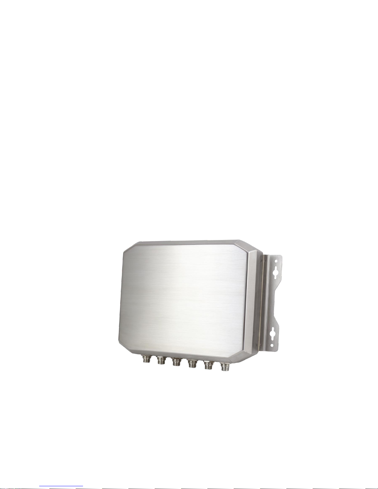
Figure 1.2: Overview of ACS-2702……………………………………………….....……...7
Figure 2.1: Mainboard Dimensions……………………………..………………..………10
Figure 2.2: Jumpers and Connectors Location_ Board Top…………………....11
Figure 2.3: Jumpers and Connectors Location_ Board Bottom………………11

ACS-2702 User Manual 5
Chapter 1 Getting Started
1.1 Features
Fanless design
Intel Atom N2600 1.6GHz CPU built-in
Onboard 2GB DDR III 800MHz
Wide Range 9~36V DC Power Input
IP67 Rating.
1.2 Specifications
System
Processor
Intel Atom Processor N2600 1.6GHz CPU
System Chipset
Intel NM10 Express Chipset
System Memory
Onboard 2GB DDR III 800MHz
Outside I/O Ports
2 x USB 2.0 type A(by 1 x M12 8pin connector)
1 x GbE LAN by Realtek RTL8111E(M12 connector)
1 x RS-232 DB-9, COM2(M12 connector)
1 x RS-232/422/485 DB-9, COM1, Default RS-232 (M12
connector)
1 x VGA (M12 connector)
1 x DC Power (M12 connector)
Storage
1 x 2.5”SATA II HDD
1 x SD slot, up to 32GB
Expansion Slots
1 x Internal Mini-PCIe slot half size
OS Support
Windows embedded standard 7, Windows 7 Pro for
embedded, Windows CE 6.0
Power
Power Input
9~36V DC
Power Consumption
MAX: 10.1W
Mechanical
Construction
Stainless Steel Chassis
Mounting
Wall Mount
IP Rating
IP67
Dimension
200 x 250 x 53 mm
Net Weight
3.2Kg

ACS-2702 User Manual 6
Environmental
Operating Temperature
-20~60 °C
Storage Temperature
-40~85 °C
Storage Temperature
10%~90%@ 40℃, non-condensing
Certificate
Meet CE / FCC
1.3 Dimensions
Figure 1.1: Dimensions of ACS-2702

ACS-2702 User Manual 7
1.4 Brief Description of ACS-2702
The ACS-2702 is a fanless high-efficiency thermal solution Box PC, powered by Intel
Atom Processor N2600 1.6GHz CPU and supporting 2GB DDR3 800 MHz onboard. It comes
with 2 x USB 2.0, 1 x LAN, 2 x COM ports, 1 x VGA and 1 x DC Power all by M12 connector. It
supports 1 x 2.5”SATAII HDD space, 1 x SD slot up to 32GB, and 9~36V DC wide-ranging
power input. It is ideal for Industrial Automation, Factory Automation, Machine Vision,
Process Control, Data Terminal, TI, Surveillance, etc. and running factory operations from
small visual interface and maintenance applications to large control process applications. The
ACS-2702 works very well along with any of our Display series and it absolutely can provide
an easy way to perform control and field maintenance.
Figure 1.2: Overview of ACS-2702

ACS-2702 User Manual 8
Chapter 2 Hardware
2.1 Motherboard Introduction
SBC-7106 is a 4" industrial motherboard developed on the basis of Intel Cedarview-M
Processors and NM10, which provides abundant peripheral interfaces to meet the needs of
different customers. Also, it features dual GbE ports, 3-COM ports and one Mini PCIE
configuration, one VGA port, one HDMI port, one LVDS interface. To satisfy the special needs
of high-end customers, CN1 and CN2 and CN3 richer extension functions. The product is
widely used in various sectors of industrial control.
2.2 Specifications
Specifications
Board Size
170mm x 113mm
CPU Support
Intel Atom N2600 /1.60GHz (2cores,3.5W, onboard)
Intel Atom D2550 /1.86GHz(2cores,10W, option)
Chipset
Intel NM10 Express
Memory Support
Onboard 2GB DDRIII SDRAM (N2600)
Onboard 4GB DDRIII SDRAM (D2550)
Graphics
Integrated Intel GMA 3600 (N2600)
Integrated Intel GMA 3650 (D2550)
Display Mode
1 x CRT Port
1 x HDMI Port
1 x LVDS1 (18/24-bit single LVDS)
Support
Resolution
Up to 1920 x1200 for CRT
Up to 1920 x1200 for HDMI
Up to 1366 x768 for LVDS1 (N2600)
Up to 1440 x 900 for LVDS1 (D2550)
Dual Display
CRT+LVDS1
CRT+HDMI
LVDS1+HDMI
Super I/O
Winbond W83627UHG-E
BIOS
AMIBIOS

ACS-2702 User Manual 9
Storage
1 x SATA Connector (7P)
1 x SATA Connector (7P+15P)
1 x SD Socket (USB to SD)
Ethernet
2 x PCIe Gbe LAN by Realtek RTL8111E
USB
2 x USB 2.0 (type A)stack ports (USB4/USB5)
2 x USB 2.0 Pin header for CN3 (USB2/USB3)
2 x USB 2.0 Pin header for CN1 (USB0/USB1)
1 x USB 2.0 for MPCIE1 (USB7)
Serial
1 x RS232/RS422/RS485 port, DB9 connector for external (COM1)
pin 9 w/5V/12V/Ring select
1 x RS232 port, DB9 connector for external (COM2)
pin 9 w/5V/12V/Ring select
1 x RS422/485 header for CN2 (COM3)
2 x UART for CN3 (COM5,COM6)
Digital I/O
8-bit digital I/O by Pin header (CN2)
4-bit digital Input
4-bit digital Output
4-bit digital I/O by Pin header (CN3)
2-bit digital Input
2-bit digital Output
Battery
Support CR2477 Li battery by 2-pin header
Audio
Support Audio via Realtek ALC662 HD audio codec
Support Line-in, Line-out, MIC by 2x6-pin header
Keyboard /Mouse
1 x PS2 keyboard/mouse by 1x6 box pin header (CN3)
Expansion Bus
1 x mini-PCI-express slot
1 x PCI-express (CN3)
Touch Ctrl
1 x Touch ctrl header for TCH1 (COM4)
Power
Management
Wide Range DC10V~30v input
1 x 3-pin power input connector
Switches and
LED Indicators
1 x Power on/off switch (CN1)
1 x Reset switch (CN1)
1 x Power LED status (CN1)
1 x HDD LED status (CN1)
1 x Buzzer

ACS-2702 User Manual 10
External I/O port
2 x COM Ports (COM1/COM2)
2 x USB 2.0 Ports (stack)
2 x RJ45 GbE LAN Ports
1 x HDMI Port
1 x Stack audio Jack (Line out)
Watchdog Timer
Software programmable 1 –255 second by Super I/O
Temperature
Operating: -20℃to 70℃
Storage: -40℃to 85℃
Humidity
5% - 95%, non-condensing, operating
Power
Consumption
12V /0.95A (Intel Atom N2600 processor with 2GB DDR3 DRAM)
EMI/EMS
Meet CE/FCC class A
(units :mm)
Figure 2.1: Motherboard Dimensions

ACS-2702 User Manual 11
2.2.1 Jumpers Setting and Connectors
Board Top
Figure 2.2: Jumpers and Connectors Location_ Board Top
Board Bottom
Figure 2.3: Jumpers and Connectors Location_ Board Bottom

ACS-2702 User Manual 12
2.3 Jumpers Setting and Connectors
1. JP5:
(2.0mm Pitch 1X2 box Pin Header), ATX Power and Auto Power on jumper setting.
JP5
Mode
Open
ATX Power
Close
Auto Power on (Default)
2. JP3:
(2.0mm Pitch 1X2 Pin Header)CMOS clear jumper, CMOS clear operation will
permanently reset old BIOS settings to factory defaults.
JP3
CM
OS
Open
NORMAL (Default)
Close 1-2
Clear CMOS
Procedures of CMOS clear:
a) Turn off the system and unplug the power cord from the power outlet.
b) To clear the CMOS settings, use the jumper cap to close pins 1 and 2 for about 3
seconds then reinstall the jumper clip back to pins open.
c) Power on the system again.
d) When entering the POST screen, press the <F1> or <DEL> key to enter CMOS Setup
Utility to load optimal defaults.
e) After the above operations, save changes and exit BIOS Setup.
Model
JP3
SBC-7106-N2600
No
SBC-7106-N2600-P
No
SBC-7106-D2550
Y
es
3. BAT1 :
(1.25mm Pitch 1X2 box Pin Header) 3.0V Li battery is embedded to provide power for
CMOS.
Pin#
Signal Name
Pin1
VBAT
PIN2
Ground
4. DC_IN1:
(5.08mm Pitch 1x3 Pin Connector),DC9V~32V System power input connector。

ACS-2702 User Manual 13
Pin#
Power Input
Pin1
DC+9V~32V
Pin2
Ground
Pin3
FG
Model
DC_IN1
SBC-7106-N2600
180°Connector
SBC-7106-N2600-P
45°C onnector
SBC-7106-D2550
45°C onnector
5. CPU_FAN1:
(2.54mm Pitch 1x3 Pin Header), Fan connector, cooling fans can be connected directly
for use. You may set the rotation condition of cooling fan in menu of BIOS CMOS Setup.
Pin#
Signal Name
1
Ground
2
VCC
3
Rotation detection
Note:
Output power of cooling fan must be limited under 5W.
Model
CPU_FAN1
SBC-7106-N2600
No
SBC-7106-N2600-P
No
SBC-7106-D2550
Y
es
6. VGA1:
(CRT 2.0mm Pitch 2X6 Pin Header), Video Graphic Array Port, Provide 2x6Pin cable to
VGA Port.
Signal Name
Pin#
Pin#
Signal Name
CRT_RED
1
2
Ground
CRT_GREEN
3
4
Ground
CRT_BLUE
5
6
VGA_EN
CRT_H_SYNC
7
8
CRT_DDCDATA
CRT_V_SYNC
9
10
CRT_DDCCLK
Ground
11
12
Ground
VGA hot plug setting for Windows XP:
VGA1(Pin Header)
Function

ACS-2702 User Manual 14
Pin4-Pin6(Close)
VGA Simulation Disabled
Pin4-Pin6(Open)
VGA Simulation Enabled
use the 2.0mm jumper cap to close pin 4 and pin6
7. HDMI1:
(HDMI 19P Connector), High Definition Multimedia Interface connector.
8. JP1:
(2.0mm Pitch 2x3 Pin Header), COM1 jumper setting, pin 1~6 are used to select signal
out of pin 9 of COM1 port.
JP1 Pin#
Function
Close 1-2
COM1 RI (Ring Indicator) (default)
Close 3-4
COM1 Pin9=+5V (option)
Close 5-6
COM1 Pin9=+12V (option)
9. S_232:
(Switch), COM1 jumper setting, it provides selectable RS232 or RS422 or RS485 serial
signal output.
Function
S_232 Pin#
RS232 (Default)
ON: Pin1, Pin2, Pin3, Pin4
RS422 (option)
OFF: Pin1, Pin2, Pin3, Pin4
RS485 (option)
OFF: Pin1, Pin2, Pin3, Pin4
10. S_422:
(Switch), COM1 setting, it provides selectable RS232 or RS422 or RS485 serial signal
output.
Function
S_422 Pin#
RS232 (Default)
OFF: Pin1, Pin2, Pin3, Pin4
RS422 (option)
ON: Pin1, Pin2, Pin3, Pin4
RS485 (option)
ON: Pin1, Pin2, Pin3, Pin4
11. COM1:
(Type DB9),Rear serial port, standard DB9 Male serial port is provided to make a
direct connection to serial devices. COM1 port is controlled by pins No.1~6 of
JP1,select output Signal RI or 5V or 12V, For details, please refer to description of JP1
and S_232 and S_422 setting.

ACS-2702 User Manual 15
RS232 (Default):
Pin#
Signal Name
1
DCD# (Data Carrier Detect)
2
RXD (Received Data)
3
TXD (Transmit Data)
4
DTR (Data Terminal Ready)
5
Ground
6
DSR (Data Set Ready)
7
RTS (Request To Send)
8
CTS (Clear To Send)
9
JP1 select Setting (RI/5V/12V)
BIOS Setup:
Advanced/W83627UHG Super IO Configuration/Serial Port
1 Configuration【RS-232】
RS422 (option):
Pin#
Signal Name
1
422_RX+
2
422_RX-
3
422_TX-
4
422_TX+
5
Ground
6
NC
7
NC
8
NC
9
NC
BIOS Setup:
Advanced/W83627UHG Super IO Configuration/Serial Port
1 Configuration【RS-422】
RS485 (option):
Pin#
Signal Name
1
NC
2
NC
3
485-
4
485+
5
Ground
6
NC
7
NC

ACS-2702 User Manual 16
8
NC
9
NC
BIOS Setup:
Advanced/W83627UHG Super IO Configuration/Serial Port
1 Configuration【RS-485】
12. JP2:
(2.0mm Pitch 2x3 Pin Header),COM2 jumper setting, pin 1~6 are used to select signal
out of pin 9 of COM2 port.
JP2 Pin#
Function
Close 1-2
COM2 RI (Ring Indicator) (default)
Close 3-4
COM2 Pin9=+5V (option)
Close 5-6
COM2 Pin9=+12V (option)
13. COM2:
(Type DB9),Rear serial port, standard DB9 Male serial port is provided to make a
direct connection to serial devices.
Pin#
Signal Name
1
DCD# (Data Carrier Detect)
2
RXD (Received Data)
3
TXD (Transmit Data)
4
DTR (Data Terminal Ready)
5
Ground
6
DSR (Data Set Ready)
7
RTS (Request To Send)
8
CTS (Clear To Send)
9
RI (Ring Indicator)
14. TCH1:
(2.0mm Pitch 1x6 box Pin Header), internal Touch controller connector.
Pin#
Signal Name
1
SENSE
2
X+
3
X-
4
Y+
5
Y-
6
GND_EARCH

ACS-2702 User Manual 17
15. JTAG1(option):
(2.0mm Pitch 2x2 Pin Header), Touch eeprom program to write interface
Signal Name
Pin#
Signal Name
3.3V
1
2
C2D_BR
YC2CK_RST
3
4
Ground
16. LED3:
LED STATUS. Green LED for Touch Power status.
17. SATA_P:
(2.5mm Pitch 1x2 box Pin Header), Two onboard 5V output connectors are reserved
to provide power for SATA devices.
Pin#
Signal Name
1
+DC5V
2
Ground
Note:
Output current of the connector must not be above 1A.
18. SATA2:
(SATA 7Pin), SATA Connectors, one SATA connectors are provided, with transfer speed
up to 3.0Gb/s.
19. SATA1:
(SATA 7Pin+15Pin), SATA Connectors, one SATA connectors are provided, with transfer
speed up to 3.0Gb/s.
20. SD1:
(SD card socket),Secure Digital Memory Card socket.
21. MPCIE1:
(Socket 52Pin),mini PCIe socket, it is located at the top, it supports mini PCIe devices
with USB2.0 and LPC and SMBUS and PCIe signal. MPCIe card size is 30x30mm.
22. AUDIO:
(2.0mm Pitch 2X6 Pin Header), Front Audio, An onboard Realtek ALC662 codec is used
to provide high-quality audio I/O ports. Line Out can be connected to a headphone or
amplifier. Line In is used for the connection of external audio source via a Line in cable.
MIC is the port for microphone input audio.

ACS-2702 User Manual 18
Signal Name
Pin#
Pin#
Signal Name
5V
1
2
GND_AUD
LINE-OUT-L
3
4
LINE-OUT-R
FRONT_JD
5
6
LINE1_JD
LINE-IN-L
7
8
LINE-IN-R
MIC-IN-L
9
10
MIC-IN-R
GND_AUD
11
12
MIC1_JD
23. LINE_OUT:
(Diameter 3.5mm Jack), HD Audio port, An onboard Realtek ALC662 codec is used to
provide high quality audio I/O ports. Line Out can be connected to a headphone or
amplifier.
24. USB45:
USB4/USB5:(Double stack USB type A), Rear USB connector, it provides up to 4
USB2.0 ports, High-speed USB 2.0 allows data transfers up to480 Mb/s ,support USB
full-speed and low-speed signaling.
Each USB Type A Receptacle (2 Ports) Current limited value is 1.5A.
If the external USB device current exceeds 1.5A, please separate connectors into
different Receptacle.
25. LAN1/LAN2:
LAN1/LAN2: (RJ45 Connector), Rear LAN port, Two standard 10/100/1000M
RJ-45 Ethernet ports are provided. Used Realtek RTL8111E chipset, LINK LED
(green) and ACTIVE LED (yellow) respectively located at the left-hand and
right-hand side of the Ethernet port indicate the activity and transmission state
of LAN.
26. BUZ1:
Onboard buzzer.

ACS-2702 User Manual 19
27. LED1:
LED STATUS. Green LED for Motherboard Power status.
28. LED2:
LED STATUS. Green LED for Motherboard Standby Power Good status.
29. CN1:
(DF13-40P Connector),For expand output connector, It provides one 18/24bit single
channel LVDS, one Backlight control, two USB ports, one power led, one HDD LED,
one power on/off button, one RESET.
Function
Signal Name
Pin#
Signal Name
Function
LVDS
12V_S0
2
1
12V_S0
LVDS
BKLT_EN_OUT
4
3
BKLT_CTRL
Ground
6
5
Ground
LVDS_VDD5
8
7
LVDS_VDD5
LVDS_VDD3
10
9
LVDS_VDD3
Ground
12
11
Ground
LA_DATAP0
14
13
LA_DATAN0
LA_DATAP1
16
15
LA_DATAN1
LA_DATAP2
18
17
LA_DATAN2
LA_DATAP3
20
19
LA_DATAN3
LA_CLKP
22
21
LA_CLKN
Ground
24
23
Ground
Ground
26
25
Ground
USB1
USB1_P
28
27
USB1_N
USB1
USB0
USB0_P
30
29
USB0_N
USB0
5V_USB01
32
31
5V_USB01
USB1
5V_USB01
34
33
5V_USB01
PWR LED
PWR_LED+
36
35
HDD_LED+
HDD LED
Ground
38
37
Ground
PWR ON/OFF
PWRBTN_ON-
40
39
FP_RST-
RESET
INVT1:
(2.0mm Pitch 1x6 Pin wafer connector), Backlight control connector for LVDS.
Pin#
Signal Name
1
+DC12V
2
+DC12V
3
Ground
Table of contents
Other Aplex Industrial PC manuals

Aplex
Aplex AHMI-8 Series User manual

Aplex
Aplex AVS-600 User manual

Aplex
Aplex AUHMI Series User manual

Aplex
Aplex AEx-2410 User manual

Aplex
Aplex AVS-301 User manual

Aplex
Aplex NV-266 C Series User manual

Aplex
Aplex ACS-2160 User manual

Aplex
Aplex ACS-2330 User manual

Aplex
Aplex ARCHMI-8 H Series User manual