Miki Pulley 121 Series User manual
MIKI PULLEY/TRS-CBUN-E-001H-00/MD-000103254 121/122/125/126
ELECTROMAGNETIC CLUTCH & BRAKE
ELECTROMAGNETIC CLUTCH AND BRAKE UNITS
121/122/125/126
Instruction Manual
☆This instruction manual describes mainly installation, removal, and notes pertaining to same for
standard-specification products after purchase; see the Miki Pulley website and our latest catalog for product
specifications and performance.
☆Before use this product, read the instruction manual carefully and use the product safely and correctly.
☆First, please check that it is the correct product and if the product was damaged during transportation.
CONTENTS
1.
STRUCTURE AND PARTS
4.
CONNECTION
2.
NOTES
5.
OPERATION CHECK
3.
MOUNTING
6.
MAINTENANCE & INSPECTION
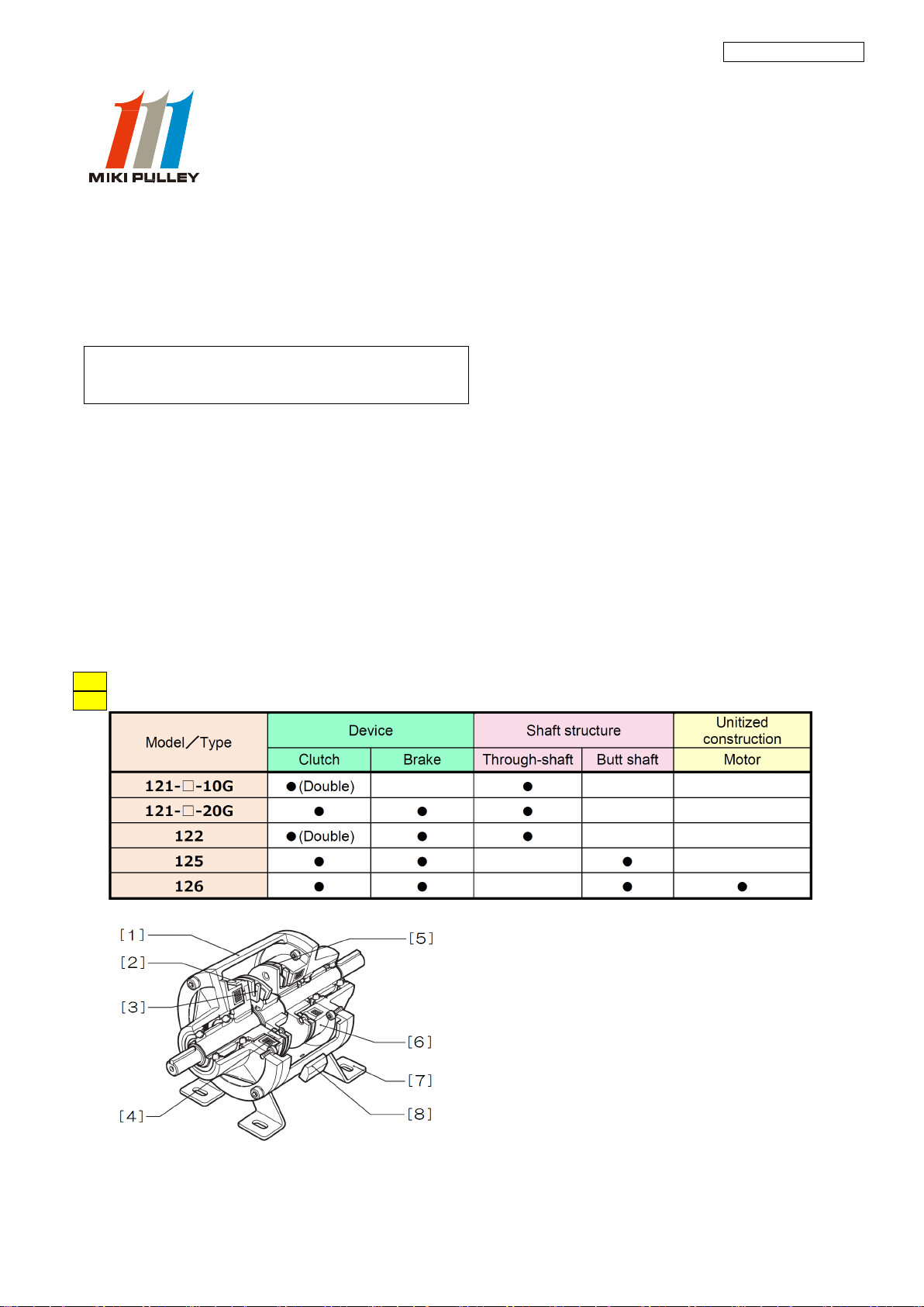
1.STRUCTURE AND PARTS
Note The device (application) and structure depend on the product model and type.
Note The base can be either steel plate or cast, depending on the product model and size.
■125
[1]Housing [2]Rotor [3]Clutch armature [4]Clutch stator
[5]Brake armature [6]Brake stator [7]Base [8]Terminal block
※Description of model names is given for Model 125
-1-

MIKI PULLEY/TRS-CBUN-E-001H-00/MD-000103254 121/122/125/126
2.NOTES
2.1 SAFETY PRECAUTIONS
Please read carefully through the instruction manual and the technical information for proper use and safety.
In this manual, safety precautions are classified by "DANGER" and "CAUTION".
【CLASS】
DANGER When death or serious injury may result by mishandling.
CAUTION When disability or only physical damage may result by mishandling.
【FIGURE SIGN】
PROHIBITION In the handling of the product, it indicates that prohibit the act.
CAUTION In the handling of the product, it indicates that attention is required.
MANDATORY In the handling of the product, it indicates that the action is compulsory on the
basis of the instructions.
DANGER
Make sure that the main power of the
product is off before mounting or
performing maintenance/inspection.
Set up a safety mechanism such as a
safety brake to avoid any danger.
It is extremely dangerous if the driving part
starts operating by accident while handling
the product.
The driven and driving sides could become
completely detached if the product is
damaged while in operation and not
immediately halted.
Do not use in flammable environments.
Be sure to use a safety cover.
There is a danger of explosion due to
sparks from machinery or the product in
operation. In particular, explosion can
occur easily in environments with
oil/grease or flammable gas.
It is extremely dangerous if hands, fingers,
hair, clothing, etc. get caught in the
product or a rotating part while in
operation.
CAUTION
Do not touch the hot clutch and brake
body or power supply.
Always use bolts specified by Miki
Pulley and a calibrated torque wrench
correctly to install brakes at the
specified tightening torque.
Hot while in operation; will result in burn
injuries if touched. Warm surroundings
will prevent clutch and brake body heat
from dissipating; locate in a
well-ventilated area.
Depending on the tightening adjustment
of bolts or screws, exceptionally
dangerous situations such as product
damage or performance degradation
could occur.
Be careful lifting a heavy weight.
Do not lift with a bad posture.
Use a safety glasses or gloves.
Straining yourself to lift a heavy product or
using a torque wrench, or an awkward
posture when installing the product in a
machine could cause back injury.
Sharp portions of product bore diameter,
keyway, shaft keyway, etc. may cause
injury. Wear protective equipment to also
prevent burn injuries and electric shock.
-2-

MIKI PULLEY/TRS-CBUN-E-001H-00/MD-000103254 121/122/125/126
2.2 IMPORTANT POINTS OF PRODUCT SPECIFICATIONS
Do not use the product in a bad
environment.
Product is for dry use; do not allow
exposure to water or oil/grease.
Request disposal with a
waste-collection company, or dispose
of according to laws and regulations.
Operating temperature range
:
-10~+40℃
Do not use the product in an environment
where water, oil, or chemicals may spill
(no matter how little), that is corrosive,
where temperature is extremely high or
low, that is dusty, where condensation
forms, that is exposed to wind and rain, or
that is subject to a high degree of
vibration/impact; may cause product
damage or performance deterioration.
When disposing of the product, request
disposal with professionals, or dispose of
according to law and local regulations if
disposing of product by yourself.
Do not dispose of or leave unattended
where children play or in a public space.
Comes as a finished product.
Do not unnecessarily disassemble,
modify, or additionally process the
product.
We do not guarantee quality nor shall we
be liable for damages in the event of
damage or affected performance of the
product or of injury or accident occurring
as a result of the product being
disassembled, modified, or additionally
processed by the customer.
2.3 IMPORTANT POINTS BEFORE MOUNTING
Do not carry with the lead wire
dangling.
Do not pull or bend the lead wire
forcefully.
Make sure to keep fluctuations in
power supply voltage to within ± 10 %
of the rated voltage.
May break wire, and render the product
unusable. If lead wire breaks or slips from
your hand, the product may fall on and
injure your foot.
Extreme fluctuations in power voltage
may prevent the product from reaching
optimal performance.
Do not use any bolt or screw other than
the bolts on the product.
Implement screw-locking measures
such as an adhesive thread-locking
compound to bolts and screws used to
install the product.
Check the strength category of the bolt or
screw as well as the strength and material
of where the product is being installed.
Inadequate strength will result in the
product being poorly installed and may
cause an accident.
Loosening of the bolts or screws due to
operational vibration, etc. may allow the
product to detach and cause an accident.
Do not bang with a hammer or other
tool when inserting a pulley or
sprocket onto the shaft or armature
hub.
Bore tolerance of the pulley or
sprocket being inserted onto the shaft
or armature hub should be finished to
H7 class.
Use the supplied insertion set.
Forcefully inserting the pulley or sprocket
may damage and affect the performance
of the product.
-3-

MIKI PULLEY/TRS-CBUN-E-001H-00/MD-000103254 121/122/125/126
3.MOUNTING
(1)
Securely fasten base on sturdy and flat surface with bolts and washers. Installation in any direction is possible.
See chart for dimensions of holes for installing base. Select the bolt length according to your design specifications.
Note
The infiltration of foreign matter into the frictional surface is undesirable. Infiltration of oils markedly degrades
frictional force. Dust, especially if it contains metal particles, can cause problems by damaging the frictional surface
and rotating parts.
Chemical infiltration can cause corrosion, in addition to the rust described above.
In such environments, consider the use of a protective cover.
(2)
When installing a pulley, sprocket, etc. on the shaft or armature hub, be sure to use screw holes at end of shaft and
on end face of armature hub and the supplied insertion set.
Do not bang on with a hammer, etc.
Note
Hexagon socket head cap screws may be supplied in place of headless bolts and hexagon nuts in the insertion set.
Note
Pulleys and sprockets require processing for holes, keyways, etc. A bore tolerance of H7 class is recommended.
-4-
MIKI PULLEY/TRS-CBUN-E-001H-00/MD-000103254 121/122/125/126
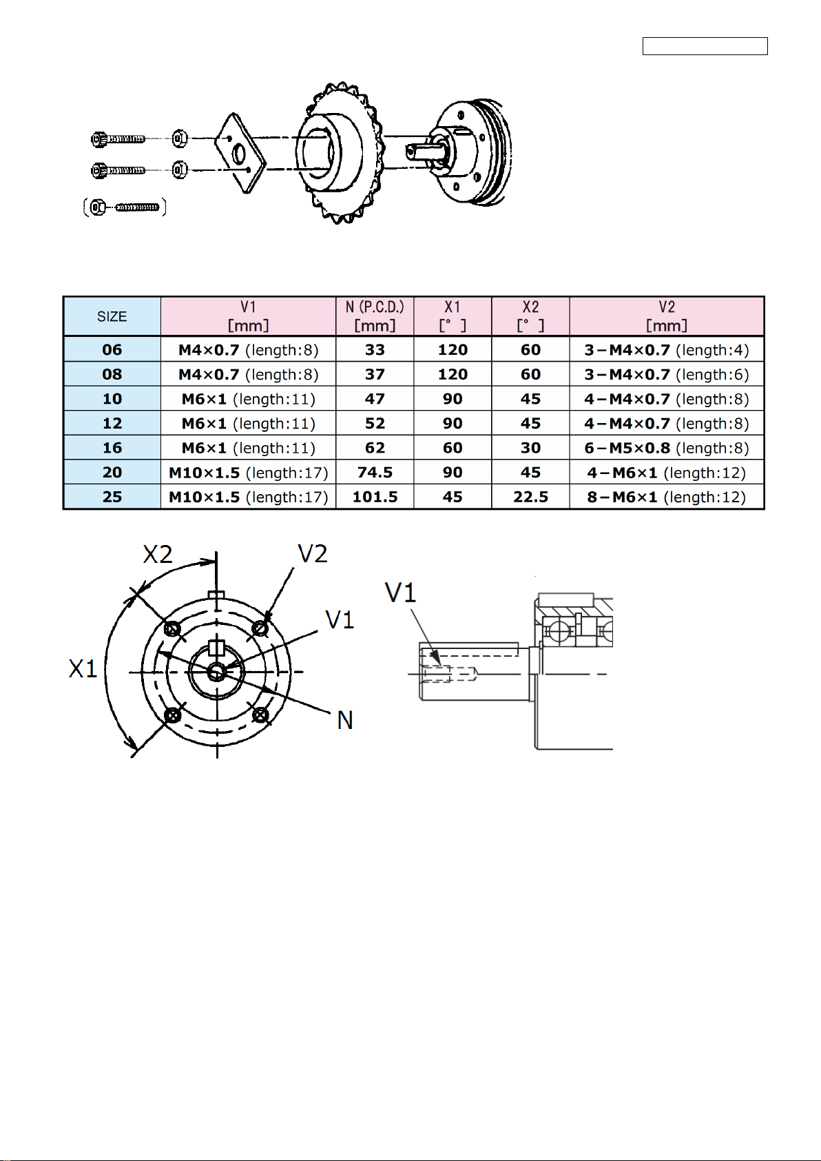
【Dimensions for screw holes at end of shaft and on end face of armature hub】
※Screw holes at end of shaft not provided with 125-05-12G.
(3)
Install the CB unit to the machine so that the travel lines are correct, and to align the centers of both shafts correctly.
The table below shows the allowable values for radial load that can be applied to the shaft of the unit.
-5-
This manual suits for next models
5
Other Miki Pulley Industrial Equipment manuals


