manuals.online logo
Brands
  1. Home
  2. •
  3. Brands
  4. •
  5. mikroElektronika
  6. •
  7. Computer Hardware
  8. •
  9. mikroElektronika 4-20mA R click User manual

mikroElektronika 4-20mA R click User manual

1. Introduction
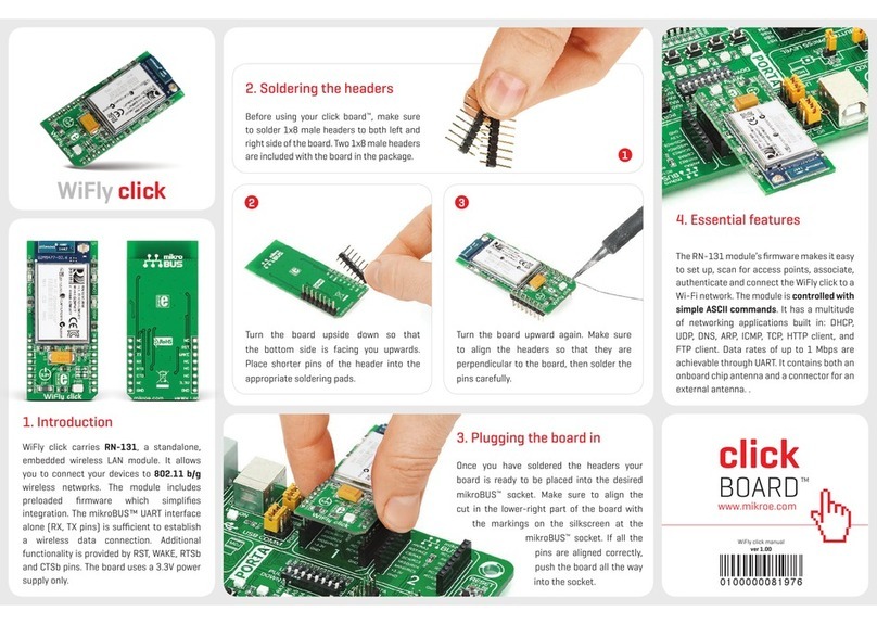
Once you have soldered the headers your
board is ready to be placed into desired
mikroBUS™ socket. Make sure to align the
cut in the lower-right part of the board
with the markings on the silkscreen at the
mikroBUS™ socket. If all of the pins are
aligned correctly, push the board all
the way into the socket.
3. Plugging the board in
2 3
2. Soldering the headers
1
4. Essential features
Turn the board upward again. Make sure
to align the headers so that they are
perpendicular to the board, then solder the
pins carefully.
Turn the board upside down so that
bottom side is facing you upwards. Place
shorter parts of the header pins in both
soldering pad locations.
click
Before using your click board™, make sure
to solder 1x8 male headers to both left
and right side of the board. Two 1x8 male
headers are included with the board in
the package.
click
BOARD
www.mikroe.com
4-20mA R click Manual
ver. 1.01
0 100000 023242
4-20mA R Click™ is an accessory board in
mikroBUS™form factor. It’s a compact and
easy solution for adding 4-to-20mA industry
standard communication protocol to your
design. It features INA196 current shunt
monitor, MCP3201 12-bit ADC as well as
TPS61041 DC/DC boost converter. 4-20mA
R Click™ communicates with target board
microcontroller via mikroBUS™SPI (SDO,
SCK, CS) and EN lines. The board is designed
to use 3.3V and 5V power supply. LED diode
indicates the presence of power supply.
4-20mA R
4-20mA R Click™ board is ideal for using in
eld of industrial process control and test
systems. The board serves as receiver in
4-20mA current loop standard. It receives
output current (4-20mA) from transmitter
and convert into a voltage (0.4-2V). Then
through the AD converter sends signal to
main board microcontroller. This board and
the 4-20mA T Click™ board together form a
complete 4-to-20mA current loop standard.
Downloaded from Arrow.com.
8. Support
MikroElektronika oers Free Tech Support
(www.mikroe.com/esupport) until the
end of product lifetime, so if something goes
wrong, we are ready and willing to help!
7. Code Examples
.com
Once you have done all the necessary
preparations, it’s time to get your click
board up and running. We have provided
the examples for mikroC, mikroBasic and
mikroPascal compilers on our Libstock
website. Just download them and you are
ready to start.
5. 4-20mA R Click™ Board Schematic
VCC
VCC
R1
2K2
LD1
C1
100nFAN
RST
CS
SCK
MOSI
MISO
+3.3V
GND
PWM
INT
RX
TX
SCL
SDA
+5V
GND
VCC-16
R3
4.99R
1
2
3
SW
GND
VIN
5
4FBEN
U2
TPS61041
L3 10uH
C2
10uF
D1
PMEG3010ER
VCC
C3
22uF
FP2
FERRITE
R6
100K
R5
1M2
C4
22pF
J1
PWR SEL
VCC-16
CN1
SCREW TERMINAL
VCC
EN
EN
OUT
OUT
VIN-
VIN-
R2
0
R4
10K
1
2
3
OUT
GND
VIN- 5
4
V+ VIN+
U3
INA196
1
2
3
54
6
7
8
Vref
IN+
IN-
Vss CS
Dout
CLK
Vdd
U1
MCP3201
1
2
3
VIN
VOUT
VSS
REF1
MAX6106EUR
C6
1uF
C8
1uFVCC
R7
10K
CS#
SCK
SDO
SDO
CS#
SCK
REF
REF
VCC
C9
100nF
C5
100nFC7
100nF
VCCVCCVCCVCC
VCC
MIKROBUS DEVICE CONN.
MikroElektronika assumes no responsibility or liability for any errors or inaccuracies that may appear in the present document.
Specication and information contained in the present schematic are subject to change at any time without notice. Copyright © 2013 MikroElektronika. All rights reserved.
6. SMD Jumper
There is one zero-ohm SMD jumper J1 used
to select whether 3.3V or 5V power supply is
used. Jumper J1 is soldered in 3.3V position by
default.
Downloaded from Arrow.com.Downloaded from Arrow.com.

Other mikroElektronika Computer Hardware manuals
mikroElektronika STEPPER 2 click User manual

mikroElektronika

mikroElektronika STEPPER 2 click User manual

mikroElektronika Current Click User manual

mikroElektronika

mikroElektronika Current Click User manual

mikroElektronika 8x8 B Click User manual

mikroElektronika

mikroElektronika 8x8 B Click User manual

mikroElektronika SpeakUp User manual

mikroElektronika

mikroElektronika SpeakUp User manual

mikroElektronika 3.3V-5V VOLTAGE TRANSLATOR MIKROE-258 User manual
mikroElektronika

mikroElektronika 3.3V-5V VOLTAGE TRANSLATOR MIKROE-258 User manual

mikroElektronika GSM2 click User manual

mikroElektronika

mikroElektronika GSM2 click User manual

mikroElektronika CO click User manual

mikroElektronika

mikroElektronika CO click User manual

mikroElektronika multimedia workStation v7 User manual

mikroElektronika

mikroElektronika multimedia workStation v7 User manual

mikroElektronika AVR-Ready1 User manual

mikroElektronika

mikroElektronika AVR-Ready1 User manual

mikroElektronika EasyMx PRO v7 User manual

mikroElektronika

mikroElektronika EasyMx PRO v7 User manual

mikroElektronika Smart ADAPT MINI User manual

mikroElektronika

mikroElektronika Smart ADAPT MINI User manual

mikroElektronika 7seg click User manual

mikroElektronika

mikroElektronika 7seg click User manual

mikroElektronika MAX232 User manual

mikroElektronika

mikroElektronika MAX232 User manual

mikroElektronika tRF click User manual

mikroElektronika

mikroElektronika tRF click User manual

mikroElektronika EasyMx PRO v7 User manual

mikroElektronika

mikroElektronika EasyMx PRO v7 User manual

mikroElektronika AlphaNum R click User manual

mikroElektronika

mikroElektronika AlphaNum R click User manual

mikroElektronika Pressure click User manual

mikroElektronika

mikroElektronika Pressure click User manual

mikroElektronika SHT1x click User manual

mikroElektronika

mikroElektronika SHT1x click User manual

mikroElektronika 4x4 RGB click User manual

mikroElektronika

mikroElektronika 4x4 RGB click User manual

mikroElektronika Click User manual

mikroElektronika

mikroElektronika Click User manual

mikroElektronika RTC click User manual

mikroElektronika

mikroElektronika RTC click User manual

mikroElektronika CAN SPI click User manual

mikroElektronika

mikroElektronika CAN SPI click User manual

mikroElektronika Series Ethernet2 User manual
mikroElektronika

mikroElektronika Series Ethernet2 User manual

mikroElektronika GSM3 click SIM800H User manual
mikroElektronika

mikroElektronika GSM3 click SIM800H User manual

Popular Computer Hardware manuals by other brands

Crown PIP-USL Specifications

Crown

Crown PIP-USL Specifications

Renesas H8 Series Hardware manual

Renesas

Renesas H8 Series Hardware manual

Joy-it SBC-LCD02 manual

Joy-it

Joy-it SBC-LCD02 manual

JETWAY G03-NU93-F Technical manual

JETWAY

JETWAY G03-NU93-F Technical manual

Mircom RB-MD-1062-15B Replacement guide

Mircom

Mircom RB-MD-1062-15B Replacement guide

ST STEVAL-IOD002V1 user manual

ST

ST STEVAL-IOD002V1 user manual

Crestron CP4-R quick start

Crestron

Crestron CP4-R quick start

ekwb EK-FC780 GTX Ti INSTALLATION AND MOUNTING MANUAL

ekwb

ekwb EK-FC780 GTX Ti INSTALLATION AND MOUNTING MANUAL

BITMINE RIG-V6 manual

BITMINE

BITMINE RIG-V6 manual

Freescale Semiconductor PowerPC MPC823 Reference manual

Freescale Semiconductor

Freescale Semiconductor PowerPC MPC823 Reference manual

ICP Electronics PX-10S user manual

ICP Electronics

ICP Electronics PX-10S user manual

Powerleap PL/586 133 installation guide

Powerleap

Powerleap PL/586 133 installation guide

Freescale Semiconductor i.MX31 PDK 1.4 quick start guide

Freescale Semiconductor

Freescale Semiconductor i.MX31 PDK 1.4 quick start guide

Renesas Converter Board R0E5212BACFK00 user manual

Renesas

Renesas Converter Board R0E5212BACFK00 user manual

Acorn BBC Master 65C102 user guide

Acorn

Acorn BBC Master 65C102 user guide

Ultra Products Media Dashboard MD3 Specifications

Ultra Products

Ultra Products Media Dashboard MD3 Specifications

IBA ibaFOB-D manual

IBA

IBA ibaFOB-D manual

ViewSonic WPD-100 VS13789 user manual

ViewSonic

ViewSonic WPD-100 VS13789 user manual

manuals.online logo
manuals.online logoBrands
  • About & Mission
  • Contact us
  • Privacy Policy
  • Terms and Conditions

Copyright 2025 Manuals.Online. All Rights Reserved.