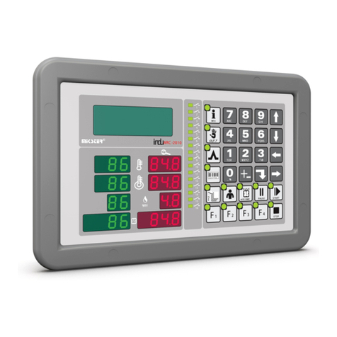
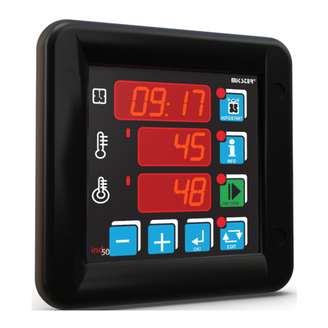
Mikster INDU-52 User manual

Industrial
Microprocessor
Controller
INDU-52
Intended for;
heat boilers, smoke houses, industrial ovens,
Sp. z o.o.
41-250 Czeladźul. Wojkowicka 21
POLAND
Tel. +48 32 763 –77– 77,
Fax: +48 32 763 –75 –94
v 1.1 17.01.2006

User’s Manual for ‘INDU-52’ v1.1
17.01.2006
2
Table of Contents
1. Application................................................................................................... 3
2. Technical Specifications.............................................................................. 3
3. Controller Operating Modes......................................................................... 4
4. Process Parameter Changing...................................................................... 4
5. Process Start............................................................................................... 5
6. Process Stop ............................................................................................... 5
7. Continuous Control Mode............................................................................ 5
8. Info............................................................................................................... 5
9. Setup........................................................................................................... 6
10. Alarms ......................................................................................................... 7
11. Notes........................................................................................................... 8

User’s Manual for ‘INDU-52’ v1.1
17.01.2006
3
1. Application
The INDU52 Controller can be used for any process control that requires two
temperature setpoints and two-channel measurements (analog inputs: PT-100 within
-50°C to 400°C). The control can be carried out continuously or depending on the
process running. The control mode can be selected in the SETUP menu.
Fig: 1 INDU-52 Controller Front Panel
2. Technical Specifications
Display LED ½ ’’ x 4 digits
LED ½ ’’ x 3 digits
Power Supply 230 (option 110, 24) VAC ±10%
Keyboard 5 keys (microswitch)
Enclosure dimensions 134x134x65 mm
Rack mount opening 90x90 mm
Inputs 2 analog inputs, PT-100
Outputs 2 relay outputs, closing contact (250 VAC/8A)
Protection IP67 (front side)
Power input 3 W
START mode
duration
settin
g
Channel 1
temperature
setpoint
SET TEMP
key –
temperature
setpoint
editing
SET TIME –
time setpoint
editing
START/STOP
key

User’s Manual for ‘INDU-52’ v1.1
17.01.2006
4
3. Controller Operating Modes
The controller can run in the following modes:
START: in this mode the process control is carried out according to the measured
temperate and the preset START mode time is counted down. Output 1 (Re1) is
controlled according to measurements made in Channel 1 (Ch1). Similarly, Output
2 (Re2) is controlled with measurements made in Channel 2 (Ch2). When the
START mode is running the SET TIME LED is flashing and the time to the end of
the START mode counted down from the set value to zero is shown in the upper
display. After the set time is elapsed the controller is switched into the STOP
mode.
STOP: the end of the START mode is indicated by “STOP” appearing on the
upper display and by an audible signal. Press the STOP key to switch into the
STANDBY mode.
STANDBY: in this mode the controller is waiting for the next operation in the
START mode. The set START mode duration is displayed on the upper display.
The current temperature measurement is shown on the bottom display.
4. Process Parameter Changing
START MODE DURATION
The START mode duration setting (hours and minutes) is shown on the upper
display. Press the SET TIME key to change the time setpoint.. Both the parameter
being edited and the SET TIME LED flash. Press the SET TIME key once again to
confirm the setting and continue. Use the PLUS / MINUS keys to change the setting.
CHANNEL 1 TEMPERATURE SETPOINT
The temperature measurement made in Channel 1 is shown on the bottom display.
Press the SET TEMP key to display and change Channel 1 temperature setpoint.
Press the SET TEMP key once again to confirm the changes. Use the PLUS /
MINUS keys to change the setting.
MOTE:
Channel 2 temperature setpoint is available in F06 in the SETUP menu.

User’s Manual for ‘INDU-52’ v1.1
17.01.2006
5
5. Process Start
Press the START key to run the process. When the START mode is activated the
START key flashes. The time to the process end is shown on the upper display. The
end of the process is indicated by “STOP” appearing on the display and by an
audible signal. Press the STOP key to confirm that the process is completed.
The temperature setpoint can be changed during the process (see section 4).
6. Process Stop
The process can be stopped at any moment by switching into the STOP mode. To
do it press the STOP key. The display shows “STOP” and an audible signal is
activated. Confirm by pressing the STOP key.
7. Continuous Control Mode
If in the SETUP menu F 1 or F 2 are set at 1, the control in selected channel is
carried out independently on the control operating mode. The START mode can be
then used for counting down and indicating a set time. Continuous Control Mode can
be selected for each channel.
8. Info
To display the temperature measurement made in another channel ,press the INFO
key. The upper display shows “INFO”. To quit this mode press the INFO key or wait
for 20 seconds to quit automatically.
When the controller is running in the START mode you can view the START mode
duration setting after pressing the SET TIME key. When this information is displayed
the SET TIME key is lit. To quit press the SET TIME key once again or wait for 3
seconds to quit automatically.

User’s Manual for ‘INDU-52’ v1.1
17.01.2006
6
9. Setup
To get into the Setup menu press and hold down the MINUS key and then press the
START key. Enter the access code with the PLUS / MINUS keys and confirm it by
pressing any SET key, if the access code function is enabled. The display shows “Fx”
indicating the Setup item. You can change the Setup item number with the PLUS /
MINUS keys. To edit the selected item press any SET key. To quit press the STOP
key.
Setup items:
Item
Number Default value Range Description
F0 1 1…127 MODBAS network address
F1 - - -
F2 0 0..1 temperature unit
0 - °C,1 - °F
F3 0 0..1 Channel 1 control
0 – START mode only,
1 – regulation in all modes
F4 0 0..1 Channel 2 control
0 – START mode only,
1 – regulation in all modes
F5 0 0..9999 SETUP access code
0 – disabled
F6 30 0..399 Channel 2 temperature setpoint
F7 150 0..399 maximum Channel 1
temperature setpoint
F8 0.2 0.0 .. 10.0 Channel 1 Low hysteresis value
F9 0.2 0.0 .. 10.0 Channel 1 High hysteresis value
F10 0.2 0.0 .. 10.0 Channel 2 Low hysteresis value
F11 0.2 0.0 .. 10.0 Channel 2 High hysteresis value

User’s Manual for ‘INDU-52’ v1.1
17.01.2006
7
10. Alarms
After power supply is switched on the measuring elements are tested by the
controller. Should a faulty measuring element is found the upper display shows “Err”
and corresponding channel number. Such information shall be confirmed by pressing
the INFO key. Further control will be carried out by using the properly operating
channel only.
Alarm messages available:
Err 1 – faulty measuring element in Channel 1
Err 2 – faulty measuring element in Channel 2
When the measuring range is exceeded or measuring element is damaged , the
display shows “---“ instead of the measured temperature.

User’s Manual for ‘INDU-52’ v1.1
17.01.2006
8
11. Notes

User’s Manual for ‘INDU-52’ v1.1
17.01.2006
9
Notes
Table of contents
Other Mikster Controllers manuals