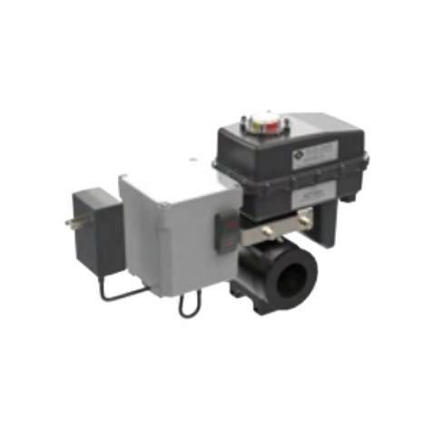
Miller-Leaman THOMPSON PDA User manual

Page 1
Table of Contents
I. Safety Consideraons..…………………………………….. 1
II. Descripon………………...…...………………...…………… 1
III. System Overview……………………………………………. 2
IV. Operaon……………………………………………...………. 3
V. Menu Screens……………..…..……………………………… 4
VI. Layout & I/O Conguraon….………….…………….. 8
VII. Electrical Connecons…………………………………… 9
VIII. Electrical Schemac……………………………………… 10
IX. Limited Warranty & Contact Info…………………… 11
I. SAFETY CONSIDERATIONS
GENERAL WARNING
Ensure all appropriate personnel read owner’s manual prior to installaon and/or operaon of controller. Failure to
Comply with instrucons and safety precauons could lead to personal injury or product damage. Please call
and ask to speak with one of our customer service representaves if there are any quesons.
CAUTION
Disconnect controller from power source before servicing or removing cover.
II. DESCRIPTION
The PDA/ATF-MAX is a dual purpose controller for both monitoring the pressure dierenal with alarm indicator and automacally controlling
the ush valve of a Thompson strainer.
OWNER’S MANUAL

Page 2
III. SYSTEM OVERVIEW
The PDA/ATF-MAX system consists of the following primary components:
The controller interface contains the controller screen and keypad interface as shown. The clear cover provides protecon for the
controller and can be opened with the two latches on the side of the controller housing to access the keypad.
A) PDA/ATF-MAX controller
B) Power supply
C) Transducer / Wiring assembly
D) Mounng bracket
E) Flush valve assembly
A) Controller Screen
B) Keypad

Page 3
Startup
1) Plug in the power plug into a standard 115VAC wall outlet
2) Upon power-up, the company informaon screen will be shown for 15 seconds.
3) Aer 15 seconds, the screen will change to the manifold pressure screen and will begin monitoring dierenal pressure across
the strainer.
Automac Flushing
Under normal operaon, a med ush will be iniated on a periodic schedule dened by the PDA/ATF-MAX programmed seng.
(every 24 hours per factory seng).
In addion, a med ush will be iniated when the dierenal pressure reaches the setpoint dened by the PDA/ATF-MAX
sengs.
See the MENU SCREENS secon for informaon on changing factory sengs.
Consecuve Flush Alarm
If three consecuve ushing operaons are detected by the PDA/ATF-MAX, a consecuve ush alarm will be triggered and no addi-
onal ush cycles will be iniated unl the alarm is cleared.
To reset the Consecuve Flush Alarm, rst, correct the cause of the alarm, then push the red ESC buon on the controller while a
Status screen is displayed. The oponal Customer’s Remote Reset input, Input iB, allows for a remote reset of the Consecuve
Flush Alarm.
Scrolling through Menu Screens
The PDA/ATF-MAX allows the operator to scroll through a selecon of menu screens by pressing the A or B buons. Press A
to scroll backward to the previous menu or press B to scroll forward to the next menu. The LCD backlight will automacally
turn on for 5 minutes when a buon is pressed, thus allowing the operator to easily view the menus in low light situaons.
Changing Parameter Values
To change an adjustable value, rst scroll to the appropriate menu screen using the A or B buon. Follow the direcons below to
modify the value.
1) The current selected value will show ashing blocks. Use the + or - keys to select another value if desired.
2) Press OK on the selected value. The value will change from ashing blocks to ashing numbers. Flashing blocks indicate the
value is locked into memory. Flashing numbers indicates the value is unlocked and can be changed.
3) Press the + or - buons to change the value. Holding the + or - buon will allow the value to increase at a faster rate aer the
rst 10 increments have passed.
4) When nished, press OK to save the change to memory. The value will return to ashing blocks.
REFER TO THE MENU SCREENS SECTION FOR DETAILED INFORMATION ON EACH SCREEN AND/OR PARAMETER.
IV. OPERATION

Page 4
V. MENU SCREENS
Miller-Leaman Inc.
800-881-0320
Power Up Screen
The Power Up screen displays the company informaon for Miller
Leaman. Each me the PDA/ATF-MAX is plugged in, or when power is
returned aer a loss, this screen will be displayed for 15 seconds. The
Power Up screen can be viewed by unplugging the PDA/ATF-MAX’s
power, then plugging it back on again.
Manifold Pressure Screen:
Aer 15 seconds, the Power Up screen will be changed to the Manifold
Pressure screen. The Manifold Pressure Screen displays the pressure in
PSI for inlet manifold, outlet manifold, and the calculated dierenal
pressure between the inlet and outlet manifolds.
Manifold Pressure
Inlet : 0034.0
Outlet : 0032.0
PSID : 0002.0
Status: OFF MAX
PSID : 00.0
Inlet Pressure Low
PSID : 00.0
Status: OFF MAX
>> High PSID <<
Status: OFF MAX
The Inlet Pressure transducer is monitored to sense sucient Inlet
Pressure and allow Timed Flushes, and Dierenal Pressure Flushing.
When the inlet pressure is sensed as lower than the Setpoint, the
Flush Interval mer will be paused, and a med Flush will not occur.
Dierenal Pressure Flushing will also be inhibited. DP sensing will
connue, and the Status Screen will display >> High PSID << on the
second line. When the Inlet Pressure is sensed as low, the top line of
the Status Screen will display Status: OFF MAX alternang with Inlet
Pressure Low.
The Status Screens
The status screens provide system feedback, allowing the operator to monitor when and how the Flush cycle is occurring. A Flush
cycle can be started manually, automacally via the Flush Interval Timer or the Pressure Dierenal Transducers (PSID), or remote-
ly by oponal Customer Input Signal.
The current status of the controller is displayed as follows:

Page 5
V. MENU SCREENS (CONT.)
Status: AUTO MAX
PSID : 0003.0
Press OK to Start
A Flush Cycle
Status: AUTO MAX
>> High PSID <<
Press OK to Start
A Flush Cycle
Status: ON MAX
Flush Cycle
Press ESC to Stop
Status: AUTO MAX
PSID : 0003.2
Press OK to Start
A Flush Cycle
Status: ON MAX
>> System Alarm <<
Press ESC to Stop
Status: AUTO MAX
Indicates that the Inlet Pressure is not Low, and the controller is waing
for a Flush cycle to begin. The system is assumed to be in normal ltra-
on mode and owing water. The Flush interval mer is running. The
controller displays Status: AUTO MAX when the Inlet Pressure in not
low and a Flush cycle has not begun. A Flush can occur from the Timer,
a high pressure dierenal via the Pressure Transducers, indicated as
>> High PSID << on the display, manually by the operator by pressing
the green OK buon on the controller, or by the Customer Input Signal.
Status: ON MAX
Indicates that the system is in a Flush cycle, iniated either by the Oper-
ator, by the Flush Interval Timer, the Pressure Transducers, or by the
Customer Input Signal. The controller will stop displaying the PSID val-
ue, but will instead indicate Flush Cycle.
The Flush Valve is opened, and the Alarm Light/Sounder output is ash-
ing. This output ashes the Light and Sounder throughout the enre
Flush cycle. The Flush Duraon is nominally set for 8 seconds. The Flush
Duraon me is adjustable - see Setup screen #3 for informaon.
Aer this Flush duraon me, the Flush Cycle is complete. The Open
Flush Valve Output will be turned o, the Alarm Light/Sounder will be
turned o, and the Status Screen will display Status: AUTO MAX.
Status: System Alarm
On any of the status screens, a System Alarm screen can be acvated.
The second line down will be alternately ashing >> System Alarm <<
and whatever was on line 2 before the system alarm occurred.
A system alarm can be any customer specic alarm. The only standard
system alarm is the Consecuve Flush Alarm. This alarm occurs when
the Flush cycle has been iniated three mes in a row by the Pressure
Transducers (PSID). Output #4 will be turned ON, which will then ener-
gize Relay 1 (R-1). Relay 1 provides a Dry Contact signal for the Custom-
er’s Consecuve Flush Alarm monitoring.
The Consecuve Flush Alarm will also cause the Alarm Light/Sounder to
change from ashing to steady ON. The Consecuve Flush Alarm will
also disable any addional Flush Cycles from occurring.

Page 6
Flush Interval & PSID Setpoint Screen
The user-dened interval at which the system will iniate an automac
Flush cycle. The Flush Interval mer resets aer any Flush cycle occurs
(by mer, PD Transducers, operator, or Customer Input Signal). This
value is adjustable from 1 minute to 1000 hrs. Seng both values to
zero will turn o the Flush mer. It is recommended that the operator
adjust the Flush interval mer so that the system Flushes by me be-
fore the pressure dierenal set-point is reached. Factory Preset value
is 24 Hours. This setpoint is located on Screen 2.
The Pressure Dierenal seng in PSI, which when compared to the
calculated Dierenal Pressure from the Inlet and Outlet pressure
transducers, will cause a Flush cycle to begin when exceeded. The rec-
ommended PD setpoint is 1-2 PSID above the “clean” PSID reading at
the systems MAXIMUM ow rate. Seng this PSID Setpoint at low ow
may result in connuous Flushing at higher ow rates, since the Pres-
sure Dierenal increases with ow rate. This value is adjustable from 1
to 30 PSID. Factory preset is 7 PSID. This set-point is located on Screen
2.
Flush Duraon Screen
The me alloed for the Flush Valve to be open. This me should be set
according to the type of lter and the nature of the material being l-
tered. This value is adjustable from 5 to 300 seconds. Factory Preset
value is 8 seconds. This setpoint is located on Screen 3. Please Note -
Flush Valve is not completely open unl 3 seconds into this me val-
ue.
V. MENU SCREENS (CONT.)
Inlet Low Pressure Setpoint Screen
The Inlet Pressure transducer is monitored to sense sucient Inlet Pres-
sure and allow Timed Flushes, and Dierenal Pressure Flushing. On
these systems, when the inlet pressure is sensed as lower than the Set-
point, the Flush Interval mer will be paused, and a med Flush will not
occur. Dierenal Pressure Flushing will also be inhibited. DP sensing
will connue, and the Status Screen will display >> High PSID << on the
second line. When the Inlet Pressure is sensed as low, the top line of
the Status Screen will display Inlet Pressure Low.
Setpoint Adjustment - The Inlet Low Pressure Setpoint is adjustable
from 5 (PSI) to 20 (PSI). Factory Preset value is 15 (PSI). This setpoint is
located on Screen 4
Inlet Low Pressure
Setpoint: 00015
Flush Duration
Seconds: 00008
Flush Interval
HOURS:MM 00024:00
Enter
PSID Setpoint 07

Page 7
Flush Counters Screen
Trip: The number of Flush cycles that have occurred since the counter
was last reset. This includes cycles iniated both manually and auto-
macally. This counter can be reset by pressing the red ESC buon from
the Flush Counters screen.
Life: The number of Flush cycles that have occurred in the controller’s
lifeme. This includes cycles iniated both manually and automacally.
This counter cannot be reset.
Time Since Last Flush & Triggered By Screen
This screen is READ ONLY for informaon and is not adjustable. The
screen shows the amount of me that has elapsed since the system last
Flushed (example: 00011:30 is 11 hours and 30 minutes) and how the
last Flush was triggered. There are four trigger possibilies:
1) Local Operator - Flush triggered manually by an operator
2) Timer - the backush was triggered by me as set on the Backush
Interval screen.
3) PD Transducer - the Flush was triggered by a high pressure dieren-
al, as set on the PSID setpoint.
4) Customer Input - Oponal Customer’s Input signal at input I1 iniat-
ed the Flush Cycle.
V. MENU SCREENS (CONT.)
Flush Counters
Trip: 00010
Life: 000000010
Press ESC to Reset
Time Since Last
Flush 00000:04
Triggered By:
PD Transducers
Controller ID Screen
This screen is READ ONLY and is used to idenfy the controller version
and ID.
Maxim4 PDA/ATF-MAX
Controller v.3.5
Copyright(c)2021
ML31155

Page 8
VI. LAYOUT & I/O CONFIGURATION
Outputs
(Note - each output’s le terminal has been connected to the 24VDC power. The output’s right terminal provides the output sig-
nal)
Output #1 controls the Flush valve.
Output #2 is not assigned.
Output #3 is a relay output for the Alarm Light/Sounder - DP Alarm is ashing and Consecuve Flush Alarm is steady.
Output #4 Consecuve Flush Alarm signal - relay output turned on when the Consecuve Flush count reaches the setpoint. This
output is wired to the coil of Relay 1 (see above) to provide a Dry Contact output.
Inputs
I1 - The oponal Customer Iniate Flush input will signal the PDA/ATF-MAX to start a Flush cycle.
IB - The oponal Customer Remote Alarm Reset input will signal the PDA/ATF-MAX to remotely reset the Consecuve Flush Alarm.
The Analog/Digital Input locaons allow Miller-Leaman Inc. to design customer specic programs. These programs are then able to
receive and process both digital and analog signals from devices such as Pressure Transducers, Flow-meters, Level Switches, etc.
Inputs IC & ID are the Inlet and Outlet Pressure Transducer connecons. These provide a 0-10Vdc signal into the controller. These
signals are converted into pressure level values and compared to each other for the pressure dierenal value. When the PD value
exceeds the PD setpoint, the PDA/ATF-MAX is signaled to start a Flush cycle. The Inlet Pressure Transducer also is used to disable
the Flush Timer and Flush Signal from Dierenal Pressure, should the Inlet Pressure be less than the Inlet Low Pressure Set-point.
Menu
Screen
Keypad
Audible / Visual
Alarm

Page 9
VII. ELECTRICAL CONNECTIONS
NOTE: When using an external power source, the input power to the Controller must be the same as indicated on the
upper le side of the PDA/ATF-MAX. Typically the controller is 24 volts DC. Plug the provided 24VDC Power Supply into
a standard 120VAC Outlet, observing all state and local codes.
Flush Valve
The Flush Valve is connected to Output#1 terminal(+ signal, white wire), Common (-) power termi-nal (Power Common, black
wire), and 24VDC (+) power terminal (Power +, red wire). Please Note - with power on and no signal, the Flush Valve will
move to its closed posion, unl it is closed.
Pressure Transducers
The Pressure Transducers have a three wire connecon, white assigned to the input (IC or ID), blue to the Common (-) terminal,
and the brown to the 24VDC Power (+) terminal .
Customer Iniated Flush Signal (Oponal)
The oponal Customer Iniate Flush Signal input is connected to Input I1. Please Note - this signal must be a discrete 24VDC
signal, that references the Common (-) terminals.
Customer Remote Alarm Reset Signal (Oponal)
The oponal Customer Remote Alarm Reset Signal input is connected to Input IB. Please Note - this signal must be a discrete
24VDC signal, that references the Common (-) terminals.
Consecuve Flush Alarm Output Signal (Dry Contact, Oponal)
Output #4 is the discrete Consecuve Flush Alarm 24VDC output signal, that is connected to the coil of Relay 1 (R-1). This relay
provides a Dry Contact connecon for Customer Consecuve Flush Alarm signal.
Review the Electrical Schemac secon prior to making any connecons to the controller.

Page 10
VIII. ELECTRICAL SCHEMATIC

1 of 5
Description: The ATF2 is an automated flush valve that is designed for use with the “Thompson” Strainer. The ATF2 has a digital
timer that allows the operator to set the frequency and duration of valve opening in order to allow more effective and efficient flushing
of the collected debris from the strainer.
Control Box: The digital timer is located inside a NEMA 4 enclosure that includes an Auto and Manual Valve function switch.
Ball Valve/Actuator: The valve body has a 316SS ball inside a UV modified, glass-filled Nylon housing. The actuator has high torque
motor gears and solid state components for increased durability and maintenance free performance contained inside a NEMA6P
enclosure.
AUTOMATIC TIMER FLUSH VALVE (ATF2)
Primary Components:
D
J
CA
E
G K
L
I
B
H M
N
F
A POWER SUPPLY
B CONTROL TOGGLE SWITCH,
3-POSITION, LIGHTED
C CONTROL BOX
D ACTUATOR HOUSING
E POWER CORD CLIP
F POWER SUPPLY JACK
G ACTUATOR CABLE
H DIGITAL TIMER
(inside control box)
I VALVE HOUSING
J STAINLESS STEEL BALL
K CONTROL BOX CABLE
L VALVE POSITION INDICATOR,
LIGHTED
M INLET PORT
N OUTLET PORT
SIDE VIEW
TOP VIEW

2 of 5
Installation for ATF2 purchased pre-installed on a strainer
1. Ensure the Control Toggle Switch is in the OFF (middle) position. You can push once toward MANUAL FLUSH and the switch
will automatically return to the OFF position.
2. Remove Power Supply from packaging.
3. Insert the 2.1mm power supply connector into the power supply jack on the bottom of the control box and run the wire through the
power cord clip on the bottom of the control box.
4. Plug the power supply into an appropriate 120 VAC electrical receptacle.
5. When power is connected, the Valve Position Indicator will glow red indicating that the valve is closed.
Installation for ATF2 purchased separately to install on strainer
1. Thread the inlet of the valve onto the flush port of the strainer. The control switch is located on the outlet side of the ATF2
package and should be facing away from the strainer when properly installed. Use caution to avoid cross threading which can
damage the valve.
2. Follow installation instructions 1 through 5 above.
Optional Power Input
If used in conjunction with the Miller-Leaman Pressure Differential Alarm (PDA or PDA2) package you have the option to power the
ATF2 by connecting a ML10808 Twisted Cable Power Connector from the Power Port Jack on the PDA/PDA2 control box to the
Power Supply Jack on the bottom of the ATF2 Control Box. Route the coiled cord through the Power Cord Clip.
ELECTRICAL SHOCK HAZARD. This device receives power from a 120VAC power source. The power supply must
be plugged into a circuit breaker protected receptacle that is designed for use in outdoor/wet locations. Any
required electrical work must be performed by a qualified electrician and must comply with all local, state and
national electrical codes.
GENERAL
The digital timer is set at the factory to initiate an 8 second flush sequence every 24 hours. Review the operational characteristics of
your application and program the timer with a flush duration and frequency that best suits your needs. Set the timer to allow longer
run time and improved performance of the strainer. The amount of debris stopped by the strainer can vary over time with changing
conditions, it is important to routinely check and inspect your system to ensure that too much debris does not accumulate in the
strainer which could result in equipment damage. The valve is configured as normally closed; however, in the event of an extended
power failure while the valve is fully or partially open, the actuator will be unable to power back to fully closed position. This could
result in water continuing to drain from the strainer until power is restored. It is important to inspect this equipment routinely to ensure
that the ATF2 has power and nothing is preventing the ball from fully closing. The valve position indicator on the top of the actuator
can be used as a visual aid to determine the position of the ball.
SAFETY CONSIDERATIONS / HAZARDS
OPERATION
MANUAL OPERATION AND INDICATORS
Control Toggle Switch, Lighted
The valve can be opened for a manual flush by pressing and holding the bottom of the Rocker Control Switch located
on the Control Box. The lower part of the switch will illuminate red in this position. The valve will remain open only
while the switch is being held down. Once the switch is released it will return to “OFF” position the valve will rotate
back to closed position. Automatic Flushing will not occur until the switch has been placed in “AUTO TIMED FLUSH”
position and the timer has been programmed. The manual flush control switch can also be used to conveniently drain
the water out of the strainer before removing the conical screen element from the strainer housing. Isolate the strainer
and utilize the pressure relief port on the lid in order to drain the strainer.
Valve Position Indicator, Lighted
A yellow indicator arrow on top of the Actuator Housing will rotate in sync with the ball valve to show the valve position.
When cutout on the yellow indicator is inline with the flush pipe, the valve is open and the indicator will glow with green
light. When the cutout on the yellow indicator is tangent to the flush pipe, the valve is closed and the indicator will
glow with red light.
PINCH POINT HAZARD. Keep fingers away from valve opening to avoid getting caught in the moving parts. The
electric motor supplies a sufficient amount of power to cause personal injury.
IMPORTANT: Any piping connected to the outlet of the valve must be plumbed to atmosphere. The flush line must
not be elevated away from the strainer and must not be piped into a pressurized line.
The Valve and Control Box are water-resistant but not water-proof. Do not install in a location where the ATF2 can
be submerged in water. Only remove the cover plate for programming. Keep cover tightly sealed at all other times.
INSTALLATION

3 of 5
Preparation for Use
1. Check that the ATF2 has power, the Valve Position Indicator is glowing red (Closed) and the Control Switch is in the OFF
position.
2. Check that the valve is operational by momentarily pressing the MANUAL FLUSH end of the Control Switch. A red indicator light
on the lower part of the switch will be visible and the valve will open. The valve will remain open as long as the switch is held in
the MANUAL FLUSH position. The valve will return to closed position when the button is released.
3. Press the AUTO FLUSH end of the Control Switch allow the Timer to control the actuation of the valve. A red indicator light on
the top part of the switch will be visible.
4. Once in AUTO FLUSH mode, the Timer will begin running the last programmed Flush & Duration sequence
General Display
Elapsed Time will display in red on the top half of the screen.
When T1 (red) is visible the Timer is showing the time (in Hours: Minutes) until the next Flush begins.
When T2 (red) is visible the Timer is showing the time (in Seconds) until the current Flush ends.
The red T1 and T2 lights will flash once per second while they are displaying the elapsed time of either function.
Set Time will display in amber on the lower half of the screen
When T1 (amber) is visible, the Timer is in FREQUENCY edit mode. The operator can adjust the time (Hours:Minutes) until next Flush
When T2 (amber) is visible the Timer is in DURATION edit mode. The operator can adjust the time (Seconds) of the Flush cycle.
The amber “OP.” light will display when the flush cycle is active.
FREQUENCY (T1) Programming
Use the SET/LOCK button to toggle between T1 and T2 programming.
When T1 (amber) is visible, the Timer is in “Frequency” edit mode.
Use the UP/DOWN DIGIT toggle buttons to select the hour(s) and minute(s) of time between flush cycles.
• Digit Toggle #1 changes frequency of flush in ten (10) hour increments.
• Digit Toggle #2 changes frequency of flush in one (1) hour increments.
• Digit Toggle #3 changes frequency of flush in ten (10) minute increments.
• Digit Toggle #4 changes frequency of flush in one (1) minute increments.
When time has been selected, push the RESET button to save the setting and begin the new cycle
Example - the Factory Setting will display as 24:00. Pushing #1 down twice, pushing #2 up one time, pushing #3 down two times,
and pushing #4 up five times will change the Frequency of flush cycle to every five hours and forty-five minutes (5:45)
When the preferred time has been selected, push the RESET button to save this time to memory.
DURATION (T2) Programming
Use the SET/LOCK button to toggle between T1 and T2 programming
When T2 (amber) is visible, the Timer is in “Duration” edit mode.
Use the UP/DOWN DIGIT toggle buttons to select the seconds of time between flush cycles.
• Digit Toggle #1 changes duration of flush in one thousand (1000) second increments.
• Digit Toggle #2 changes duration of flush in one hundred (100) second increments.
• Digit Toggle #3 changes duration of flush in ten (10) second increments.
• Digit Toggle #4 changes duration of flush in one (1) second increments.
When time has been selected, push the RESET button to save the setting and begin the new cycle.
Example - the Factory Setting will display as 8. Pushing the #1, #2, #3 digit buttons up once and the #4 digit button up twice will
change the duration of the flush cycle to one thousand one hundred and ten (1110) seconds or 18.5 minutes.
Valve Cycle Time: The cycle time of the valve, the time it takes to rotate from closed to open and back to closed, is approximately 8
seconds and the ball will only be fully open briefly in between the opening and closing function. To have the ball remain fu lly open for
10 seconds, set the Duration of the flush to be 18 seconds (4 seconds of opening time, 10 seconds fully open, 4 seconds of closing
time).
ADDITIONAL FUNCTIONS
RESET TIMER - Press the RESET button at any time to restart the T1 / Frequency timer.
LOCK OUT - Press and hold the SET/LOCK button and the DIGIT #1 button at the same time to enter “Lock” mode. The amber
“LOCK” button will show on the display screen and all buttons will be disabled. Repeat to unlock this function.
AUTOMATIC PROGRAMMING INSTRUCTIONS

4 of 5
#1 #2 #3 #4
.
UP / DOWN DIGIT Button
T1/T2 operation indicator
T1/T2 setting value indicator
Output indicator
Lock indicator
RESET Button
SET/LOCK Button
Set Time Display
Elapsed Time Display
DISPLAY
DISPLAY VALVE CLOSED VALVE OPEN
T1 OPERATION INDICATOR (RED) Flashing once per second Not Visible
T2 OPERATION INDICATOR (RED) Not Visible Flashing once per second
ELAPSED TIME DISPLAY (RED) Hours:Minutes until flush begin Seconds until flush end
OUTPUT INDICATOR(AMBER) Not Visible Visible
DISPLAY SETTING FUNCTION
SET TIME DISPLAY (AMBER) Displays either T1 or T2 Set Value. Use SET/LOCK button to toggle between
T1 SET VALUE INDICATOR (AMBER) Displayed when showing/editing T1 setting
T2 SET VALUE INDICATOR (AMBER) Displayed when showing/editing T2 setting
BUTTON
BUTTON ACTION
RESET Set time selections and Clear Flush
SET/LOCK Toggle between T1 and T2 Setting . Lock screen (Push Lock and Digit 1 together)
BUTTON T1 / FREQUENCY PROGRAMMING T2 / DURATION PROGRAMMING
DIGIT 1 Adjust by 10 hour increment Adjust by 1000 second increment
DIGIT 2 Adjust by 1 hour increment Adjust by 100 second increment
DIGIT 3 Adjust by 10 minute increment Adjust by 10 second increment
DIGIT 4 Adjust by 1 minute increment Adjust by 1 second increment
SYMBOL FLUSH FACTORY SETTING
T1 FREQUENCY 24:00
T2 DURATION 8
DIGITAL TIMER BUTTON AND DISPLAY INFORMATION

5 of 5
ATF2 WIRING SCHEMATIC AND POWER REQUREMENTS
Office Hours: 8 AM – 5 PM Eastern Time
Web: www.millerleaman.com
Email: support@millerleaman.com
800 Orange Avenue, Daytona Beach, FL 32114
Phone: (386) 248-0500 / Fax: (386) 248-3033
ML40198 (2022)
MODEL NUMBER NPT PIPE SIZE VALVE BALL/BODY MAXIMUM PRESSURE
ATF2-075 3/4” 316SS / Nylon 150 PSI @ 70 deg. F
ATF2-100 1" 316SS / Nylon 150 PSI @ 70 deg. F
ATF2-150 1-1/2" 316SS / Nylon 150 PSI @ 70 deg. F
ATF2-200 2" 316SS / Nylon 150 PSI @ 70 deg. F
ATF2-300 3" 316SS / Polypropylene 100 PSI @ 70 deg. F
ATF2 MODEL INFORMATION
Illuminated Rocker Switch
AUTO - Valve operates on Timer
MANUAL - Valve opens Momentary
POWER SUPPLY SPECIFICATION
AC/DC SWITCHING ADAPTOR
INPUT: 100-240 VAC, 50/60 Hz, .6A
OUTPUT: 12V, 2.08A, 25W MAX
REV. 6/22/22

Page 1 of 3
Description: The pressure differential alarm package continually monitors and displays the strainer’s inlet and outlet differential
pressure. When the strainer element (conical strainer basket) becomes significantly clogged, the pressure differential switch-gauge
will trigger an audible siren and a visual flashing alarm light. These alarms are intended to alert maintenance personnel that the
strainer element must be removed and cleaned (see your Thompson Strainer Owner’s Manual for complete strainer element cleaning
instructions).
I. PRESSURE DIFFERENTIAL ALARM PACKAGE (PDA2)
PRESSURE DIFFERENTIAL ALARM PACKAGE OVERVIEW (PDA2)
Installation Instructions:
The following instructions are to be used as a guide when installing the PDA on to an existing Thompson Strainer
1. Place the PDA enclosure with the black bracket over the high and low gauge ports on the side of the strainer housing.
2. While applying pressure to the enclosure and bracket, tighten the (2) 10-24 stainless steel set screws to secure the bracket on
the gauge ports.
3. Connect the blue 1/4” tube into the upper gauge port.
4. Connect the black 1/4” tube into the lower gauge port.
Power Port for
Cable to ATF
(Optional)
Wall Power Supply
Input - 115VAC
Output - 12VDC
Power Cable
Retainer
Visual &
Audible
Alarm
LED Power Indicator
Differential Set-Point
Contact Adjust Knob
Pressure Differential
Switch-Gauge
Alarm Reset Button
Outlet Port Tubing,
Blue, Low PSI
Inlet Port Tubing,
Black, High PSI
Customer’s
Dry Contact Alarm
Cable Port
Cover-Plate Thumb Screws (2)
Enclosure’s Clear
Cover Latch
Enclosure’s Clear
Cover Latch
Cover-Plate

Page 2 of 3
Alarm Output - Customer’s Dry Contact:
See illustration on front page. The PC Board has been factory set up for a 12 VDC Output to the Relay 2 coil when the alarm
activates. Relay 2 provides a Dry Contact for the optional use by the Customer. A cable strain relief port has been provided for the
Customer’s wiring to this Dry Contact Alarm signal. A maximum switching power of 24VDC 0.5 Amp is recommended.
(Please see the PDA2 Electrical Schematic below, on page 3 of this manual. If you have any additional questions please contact MLI
Water Resistance:
The Pressure Differential Alarm Controller is water-proof, but not submersible. Do not install below ground level where the box can be
submerged in water. Keep the enclosure’s Clear cover latched during normal operation. Insure all strain reliefs have be properly tight-
ened to maintain this Nema 4X integrity. Periodically check inside the enclosure, with the power disconnected, and the cover plate
opened, for any signs of leakage.
Miller-Leaman, Inc. Return Policy:
Units in need of warranty repair and less than 90-days old, must be returned to MLI accompanied by a Return Material Authorization
(RMA) number. To request a RMA number call (386) 248-0500.
Maintenance:
The PDA alarm should be checked on a routine basis by contacting the differential set-point (see illustration on first page) so that the
audible and visual alarm engages and the alarm-reset button deactivates the alarms.
II. GENERAL INFORMATION
Operation Instructions:
Remove the power supply from the box and insert the connector end into the socket on the bottom of the PDA housing, as indicated in
the drawing above. Plug the power supply into a nominal 120VAC power outlet. Standard systems are supplied with a Wall Plug-In
12VDC Power Supply, with an input power of 120VAC.
Please Note - In the case of an “Outdoor” use application, where there is a chance that the unit could get wet, it is the Cus-
tomer’s responsibility to provide a safe power outlet, in terms of being water proof, and physically able to accept the plug-in
power supply we provide. Miller - Leaman, Inc. also recommends that the installation be only performed by a qualified elec-
trician, and that all Local, State, and National Electrical Codes be followed.
The pressure differential switch-gauge is factory set to 7-8 PSI. Since the Thompson Strainer operates with less than 1 PSI loss
during maximum flow when the strainer screen is clean, the differential shown on the switch-gauge will be 1 PSI. Therefore, by the
time the differential pressure rises to 7-8 PSI, the strainer element will have become significantly clogged and will require immediate
removal and cleaning.
To adjust the pressure differential switch-gauge to a lower setting, simply turn the small black knob to move the differential set-point
contact (see illustration above) to the desired location.
WE DO NOT RECOMMEND SETTING THE DIFFERENTIAL SWITCH-GAUGE HIGHER THAN 10 PSI. DISABLING THE ALARM
OR INCREASING THE ALARM SET POINT COULD RESULT IN DAMAGE TO THE STRAINER ELEMENT AND ALLOW DEBRIS
TO PASS INTO THE SYSTEM.
The alarm will latch-ON when the differential set point is reached and will stay latched until the Reset button is pressed. (If the Reset
button is pressed but the strainer remains beyond the acceptable differential pressure, the alarm will re-latch immediately). The
purpose of the alarm package is to alert maintenance personnel that the strainer element requires cleaning. Therefore, if the Alarm
Light is flashing, and has sounded, the strainer needs to be taken off-line and the strainer element needs to be cleaned as instructed
in the STRAINER ELEMENT CLEANING section of the Thompson Strainer Owner’s Manual.
After the strainer is cleaned and put back in service, the differential pressure should be back to 1 PSI. If the switch-gauge indicates a
1 PSI differential but the alarm is still sounding, press the Reset button.
If you have any questions about the Pressure Differential Alarm Package, please call our product specialists at (386) 248-0500. You

Page 3 of 3
III. PDA2 WIRING SCHEMATIC
Office Hours: 8 AM – 5 PM Eastern Time
Web: www.millerleaman.com
Email: support@millerleaman.com
800 Orange Avenue, Daytona Beach, FL 32114
Phone: (386) 248-0500 / Fax: (386) 248-3033
ML40191 (2022) REV. 6/22/22
This manual suits for next models
1
Table of contents
Other Miller-Leaman Control Unit manuals
Popular Control Unit manuals by other brands
ABB
ABB OHDI-01 user manual
LEUSCH
LEUSCH LTR 43 Series Operating and service instructions
Allen-Bradley
Allen-Bradley 1757-ABRIO user manual
Zator
Zator B2755 00 Series User and maintenance manual

Ingersoll-Rand
Ingersoll-Rand RR250-F30 Installation and maintenance information
Yamaha
Yamaha MusicCAST MCX-CA15 Install manual
Energeeks
Energeeks EG-VALV001 Quick installation guide
CyberPower
CyberPower OR750PFCLCD Function setup guide
STIEBEL ELTRON
STIEBEL ELTRON SBP 200 E Operation and installation

Ferro
Ferro KP Installation and maintenance manual

Avalue Technology
Avalue Technology ESM-2850 Quick installation guide

Unex
Unex SOM-300 Series quick start guide
