Miller-Leaman THOMSON ATF2 User manual
1 of 5
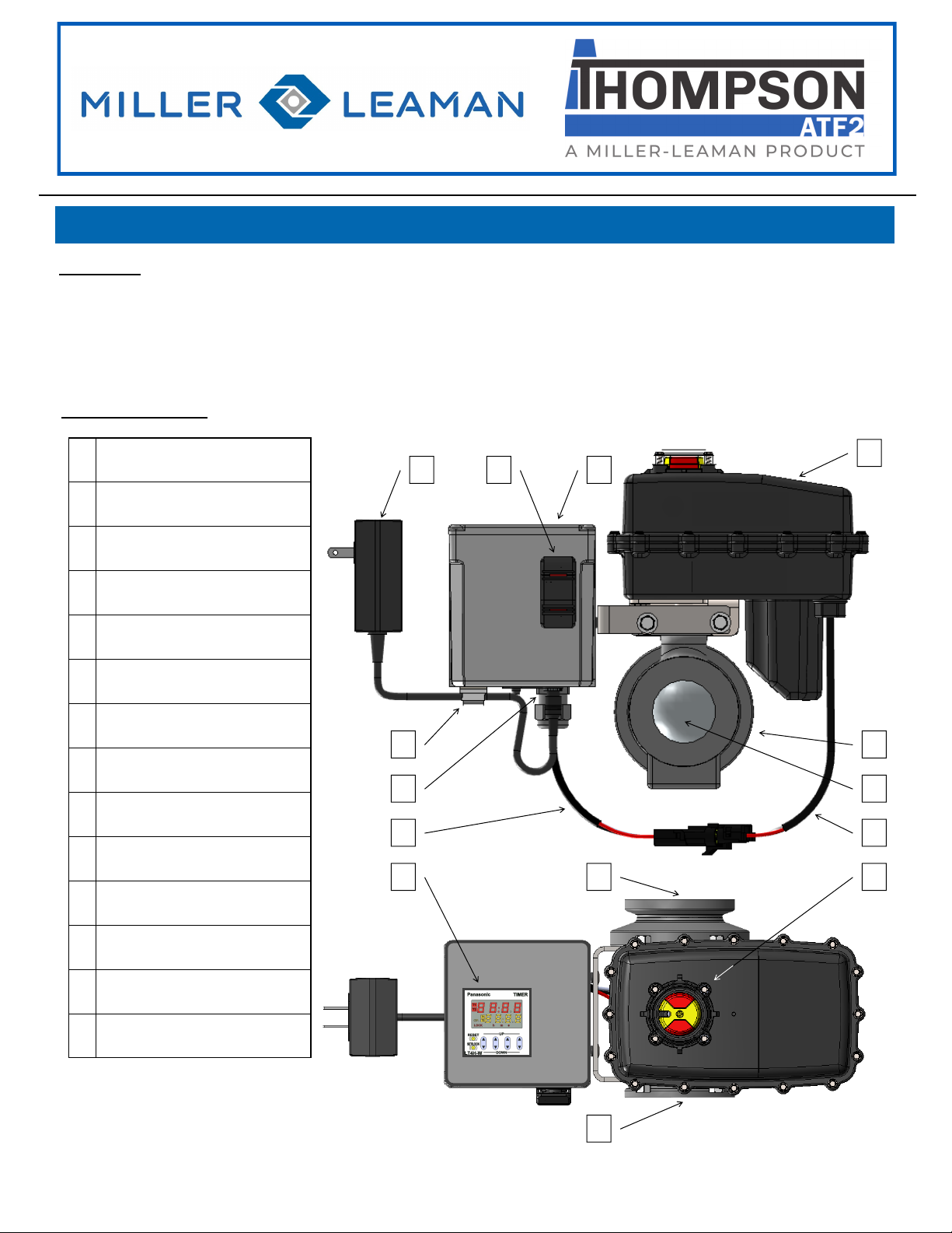
Description: The ATF2 is an automated flush valve that is designed for use with the “Thompson” Strainer. The ATF2 has a digital
timer that allows the operator to set the frequency and duration of valve opening in order to allow more effective and efficient flushing
of the collected debris from the strainer.
Control Box: The digital timer is located inside a NEMA 4 enclosure that includes an Auto and Manual Valve function switch.
Ball Valve/Actuator: The valve body has a 316SS ball inside a UV modified, glass-filled Nylon housing. The actuator has high torque
motor gears and solid state components for increased durability and maintenance free performance contained inside a NEMA6P
enclosure.
AUTOMATIC TIMER FLUSH VALVE (ATF2)
Primary Components:
D
J
CA
E
G K
L
I
B
H M
N
F
A POWER SUPPLY
B CONTROL TOGGLE SWITCH,
3-POSITION, LIGHTED
C CONTROL BOX
D ACTUATOR HOUSING
E POWER CORD CLIP
F POWER SUPPLY JACK
G ACTUATOR CABLE
H DIGITAL TIMER
(inside control box)
I VALVE HOUSING
J STAINLESS STEEL BALL
K CONTROL BOX CABLE
L VALVE POSITION INDICATOR,
LIGHTED
M INLET PORT
N OUTLET PORT
SIDE VIEW
TOP VIEW

2 of 5
Installation for ATF2 purchased pre-installed on a strainer
1. Ensure the Control Toggle Switch is in the OFF (middle) position. You can push once toward MANUAL FLUSH and the switch
will automatically return to the OFF position.
2. Remove Power Supply from packaging.
3. Insert the 2.1mm power supply connector into the power supply jack on the bottom of the control box and run the wire through the
power cord clip on the bottom of the control box.
4. Plug the power supply into an appropriate 120 VAC electrical receptacle.
5. When power is connected, the Valve Position Indicator will glow red indicating that the valve is closed.
Installation for ATF2 purchased separately to install on strainer
1. Thread the inlet of the valve onto the flush port of the strainer. The control switch is located on the outlet side of the ATF2
package and should be facing away from the strainer when properly installed. Use caution to avoid cross threading which can
damage the valve.
2. Follow installation instructions 1 through 5 above.
Optional Power Input
If used in conjunction with the Miller-Leaman Pressure Differential Alarm (PDA or PDA2) package you have the option to power the
ATF2 by connecting a ML10808 Twisted Cable Power Connector from the Power Port Jack on the PDA/PDA2 control box to the
Power Supply Jack on the bottom of the ATF2 Control Box. Route the coiled cord through the Power Cord Clip.
ELECTRICAL SHOCK HAZARD. This device receives power from a 120VAC power source. The power supply must
be plugged into a circuit breaker protected receptacle that is designed for use in outdoor/wet locations. Any
required electrical work must be performed by a qualified electrician and must comply with all local, state and
national electrical codes.
GENERAL
The digital timer is set at the factory to initiate an 8 second flush sequence every 24 hours. Review the operational characteristics of
your application and program the timer with a flush duration and frequency that best suits your needs. Set the timer to allow longer
run time and improved performance of the strainer. The amount of debris stopped by the strainer can vary over time with changing
conditions, it is important to routinely check and inspect your system to ensure that too much debris does not accumulate in the
strainer which could result in equipment damage. The valve is configured as normally closed; however, in the event of an extended
power failure while the valve is fully or partially open, the actuator will be unable to power back to fully closed position. This could
result in water continuing to drain from the strainer until power is restored. It is important to inspect this equipment routinely to ensure
that the ATF2 has power and nothing is preventing the ball from fully closing. The valve position indicator on the top of the actuator
can be used as a visual aid to determine the position of the ball.
SAFETY CONSIDERATIONS / HAZARDS
OPERATION
MANUAL OPERATION AND INDICATORS
Control Toggle Switch, Lighted
The valve can be opened for a manual flush by pressing and holding the bottom of the Rocker Control Switch located
on the Control Box. The lower part of the switch will illuminate red in this position. The valve will remain open only
while the switch is being held down. Once the switch is released it will return to “OFF” position the valve will rotate
back to closed position. Automatic Flushing will not occur until the switch has been placed in “AUTO TIMED FLUSH”
position and the timer has been programmed. The manual flush control switch can also be used to conveniently drain
the water out of the strainer before removing the conical screen element from the strainer housing. Isolate the strainer
and utilize the pressure relief port on the lid in order to drain the strainer.
Valve Position Indicator, Lighted
A yellow indicator arrow on top of the Actuator Housing will rotate in sync with the ball valve to show the valve position.
When cutout on the yellow indicator is inline with the flush pipe, the valve is open and the indicator will glow with green
light. When the cutout on the yellow indicator is tangent to the flush pipe, the valve is closed and the indicator will
glow with red light.
PINCH POINT HAZARD. Keep fingers away from valve opening to avoid getting caught in the moving parts. The
electric motor supplies a sufficient amount of power to cause personal injury.
IMPORTANT: Any piping connected to the outlet of the valve must be plumbed to atmosphere. The flush line must
not be elevated away from the strainer and must not be piped into a pressurized line.
The Valve and Control Box are water-resistant but not water-proof. Do not install in a location where the ATF2 can
be submerged in water. Only remove the cover plate for programming. Keep cover tightly sealed at all other times.
INSTALLATION

3 of 5
Preparation for Use
1. Check that the ATF2 has power, the Valve Position Indicator is glowing red (Closed) and the Control Switch is in the OFF
position.
2. Check that the valve is operational by momentarily pressing the MANUAL FLUSH end of the Control Switch. A red indicator light
on the lower part of the switch will be visible and the valve will open. The valve will remain open as long as the switch is held in
the MANUAL FLUSH position. The valve will return to closed position when the button is released.
3. Press the AUTO FLUSH end of the Control Switch allow the Timer to control the actuation of the valve. A red indicator light on
the top part of the switch will be visible.
4. Once in AUTO FLUSH mode, the Timer will begin running the last programmed Flush & Duration sequence
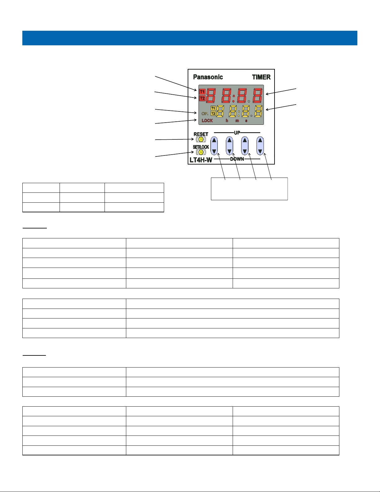
General Display
Elapsed Time will display in red on the top half of the screen.
When T1 (red) is visible the Timer is showing the time (in Hours: Minutes) until the next Flush begins.
When T2 (red) is visible the Timer is showing the time (in Seconds) until the current Flush ends.
The red T1 and T2 lights will flash once per second while they are displaying the elapsed time of either function.
Set Time will display in amber on the lower half of the screen
When T1 (amber) is visible, the Timer is in FREQUENCY edit mode. The operator can adjust the time (Hours:Minutes) until next Flush
When T2 (amber) is visible the Timer is in DURATION edit mode. The operator can adjust the time (Seconds) of the Flush cycle.
The amber “OP.” light will display when the flush cycle is active.
FREQUENCY (T1) Programming
Use the SET/LOCK button to toggle between T1 and T2 programming.
When T1 (amber) is visible, the Timer is in “Frequency” edit mode.
Use the UP/DOWN DIGIT toggle buttons to select the hour(s) and minute(s) of time between flush cycles.
• Digit Toggle #1 changes frequency of flush in ten (10) hour increments.
• Digit Toggle #2 changes frequency of flush in one (1) hour increments.
• Digit Toggle #3 changes frequency of flush in ten (10) minute increments.
• Digit Toggle #4 changes frequency of flush in one (1) minute increments.
When time has been selected, push the RESET button to save the setting and begin the new cycle
Example - the Factory Setting will display as 24:00. Pushing #1 down twice, pushing #2 up one time, pushing #3 down two times,
and pushing #4 up five times will change the Frequency of flush cycle to every five hours and forty-five minutes (5:45)
When the preferred time has been selected, push the RESET button to save this time to memory.
DURATION (T2) Programming
Use the SET/LOCK button to toggle between T1 and T2 programming
When T2 (amber) is visible, the Timer is in “Duration” edit mode.
Use the UP/DOWN DIGIT toggle buttons to select the seconds of time between flush cycles.
• Digit Toggle #1 changes duration of flush in one thousand (1000) second increments.
• Digit Toggle #2 changes duration of flush in one hundred (100) second increments.
• Digit Toggle #3 changes duration of flush in ten (10) second increments.
• Digit Toggle #4 changes duration of flush in one (1) second increments.
When time has been selected, push the RESET button to save the setting and begin the new cycle.
Example - the Factory Setting will display as 8. Pushing the #1, #2, #3 digit buttons up once and the #4 digit button up twice will
change the duration of the flush cycle to one thousand one hundred and ten (1110) seconds or 18.5 minutes.
Valve Cycle Time: The cycle time of the valve, the time it takes to rotate from closed to open and back to closed, is approximately 8
seconds and the ball will only be fully open briefly in between the opening and closing function. To have the ball remain fully open for
10 seconds, set the Duration of the flush to be 18 seconds (4 seconds of opening time, 10 seconds fully open, 4 seconds of closing
time).
ADDITIONAL FUNCTIONS
RESET TIMER - Press the RESET button at any time to restart the T1 / Frequency timer.
LOCK OUT - Press and hold the SET/LOCK button and the DIGIT #1 button at the same time to enter “Lock” mode. The amber
“LOCK” button will show on the display screen and all buttons will be disabled. Repeat to unlock this function.
AUTOMATIC PROGRAMMING INSTRUCTIONS
4 of 5
#1 #2 #3 #4
.
UP / DOWN DIGIT Button
T1/T2 operation indicator
T1/T2 setting value indicator
Output indicator
Lock indicator
RESET Button
SET/LOCK Button
Set Time Display
Elapsed Time Display
DISPLAY
DISPLAY VALVE CLOSED VALVE OPEN
T1 OPERATION INDICATOR (RED) Flashing once per second Not Visible
T2 OPERATION INDICATOR (RED) Not Visible Flashing once per second
ELAPSED TIME DISPLAY (RED) Hours:Minutes until flush begin Seconds until flush end
OUTPUT INDICATOR(AMBER) Not Visible Visible
DISPLAY SETTING FUNCTION
SET TIME DISPLAY (AMBER) Displays either T1 or T2 Set Value. Use SET/LOCK button to toggle between
T1 SET VALUE INDICATOR (AMBER) Displayed when showing/editing T1 setting
T2 SET VALUE INDICATOR (AMBER) Displayed when showing/editing T2 setting
BUTTON
BUTTON ACTION
RESET Set time selections and Clear Flush
SET/LOCK Toggle between T1 and T2 Setting . Lock screen (Push Lock and Digit 1 together)
BUTTON T1 / FREQUENCY PROGRAMMING T2 / DURATION PROGRAMMING
DIGIT 1 Adjust by 10 hour increment Adjust by 1000 second increment
DIGIT 2 Adjust by 1 hour increment Adjust by 100 second increment
DIGIT 3 Adjust by 10 minute increment Adjust by 10 second increment
DIGIT 4 Adjust by 1 minute increment Adjust by 1 second increment
SYMBOL FLUSH FACTORY SETTING
T1 FREQUENCY 24:00
T2 DURATION 8
DIGITAL TIMER BUTTON AND DISPLAY INFORMATION
5 of 5
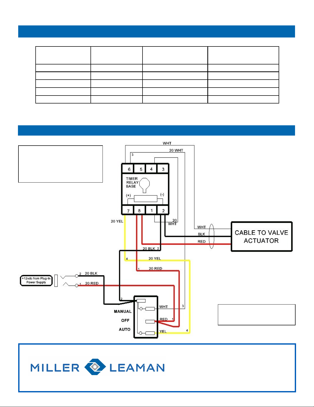
ATF2 WIRING SCHEMATIC AND POWER REQUREMENTS
Office Hours: 8 AM – 5 PM Eastern Time
Web: www.millerleaman.com
Email: support@millerleaman.com
800 Orange Avenue, Daytona Beach, FL 32114
Phone: (386) 248-0500 / Fax: (386) 248-3033
ML40198 (2022)
MODEL NUMBER NPT PIPE SIZE VALVE BALL/BODY MAXIMUM PRESSURE
ATF2-075 3/4” 316SS / Nylon 150 PSI @ 70 deg. F
ATF2-100 1" 316SS / Nylon 150 PSI @ 70 deg. F
ATF2-150 1-1/2" 316SS / Nylon 150 PSI @ 70 deg. F
ATF2-200 2" 316SS / Nylon 150 PSI @ 70 deg. F
ATF2-300 3" 316SS / Polypropylene 100 PSI @ 70 deg. F
ATF2 MODEL INFORMATION
Illuminated Rocker Switch
AUTO - Valve operates on Timer
MANUAL - Valve opens Momentary
POWER SUPPLY SPECIFICATION
AC/DC SWITCHING ADAPTOR
INPUT: 100-240 VAC, 50/60 Hz, .6A
OUTPUT: 12V, 2.08A, 25W MAX
REV. 6/22/22
This manual suits for next models
5
Table of contents
Other Miller-Leaman Control Unit manuals


