Miller MP-10 Series User manual

®
Passive Welding Helmets
MP-10 Series
OM-235 589B
2015−04
To help us serve you better, go to www.MillerWelds.Com/Register

TABLE OF CONTENTS
SECTION 1 −WELDING HELMET SAFETY PRECAUTIONS −READ BEFORE USING 1..
1-1. Symbol Usage 1..........................................................
1-2. Arc Welding Hazards 1.....................................................
1-3. Proposition 65 Warnings 3..................................................
1-4. Lens Shade Selection Table 3...............................................
1-5. Principal Safety Standards 3................................................
SECTION 2 −SPECIFICATIONS 4..................................................
SECTION 3 −OPERATING INSTRUCTIONS 4.......................................
3-1. Adjusting Headgear 5......................................................
3-2. Replacing Lens and Lens Covers 6...........................................
3-3. Installing Optional Magnifying Lens 7.........................................
SECTION 4 −MAINTENANCE 7...................................................
SECTION 5 −PARTS LIST 8.......................................................
SECTION 6 −LIMITED WARRANTY 9..............................................

OM-235 589 Page 1
SECTION 1 −WELDING HELMET SAFETY PRECAUTIONS −
READ BEFORE USING
helmet 2013-09
Protect yourself and others from injury — read, follow, and save these important safety
precautions and operating instructions.
1-1. Symbol Usage
This group of symbols means Warning! Watch
Out! ELECTRIC SHOCK, MOVING PARTS,
and HOT PARTS hazards. Consult symbols
and related instructions below for necessary
actions to avoid the hazards.
Indicates special instructions.
DANGER! −Indicates a hazardous
situation which, if not avoided, will
result in death or serious injury. The
possible hazards are shown in the
adjoining symbols or explained in
the text.
Indicates a hazardous situation
which, if not avoided, could result in
death or serious injury. The possible
hazards are shown in the adjoining
symbols or explained in the text.
NOTICE −Indicates statements not related to
personal injury.
1-2. Arc Welding Hazards
Only qualified persons should install, operate, maintain, and repair this unit.
Arc rays from the welding process produce intense visible and invisible (ultravio-
let and infrared) rays that can burn eyes and skin. Sparks fly off from the weld.
Wear a welding helmet fitted with a proper shade of filter to protect your face and eyes when
welding or watching (see ANSI Z49.1 and Z87.1 listed in Safety Standards). Refer to Lens
Shade Selection table in Section 1-4.
Wear approved safety glasses with side shields under your helmet.
Use protective screens or barriers to protect others from flash, glare, and sparks; warn
others not to watch the arc.
Wear body protection made from durable, flame−resistant material (leather, heavy cotton,
wool). Body protection includes oil-free clothing such as leather gloves, heavy shirt, cuffless
trousers, high shoes, and a cap.
•Before welding, adjust the auto-darkening lens sensitivity setting to meet the application.
•Stop welding immediately if the auto-darkening lens does not darken when the arc is struck.
See the Owner’s Manual for more information.
ARC RAYS can burn eyes and skin.

OM-235 589 Page 2
WELDING HELMETS do not provide unlimited eye, ear, and
face protection.
Arc rays from the welding process produce intense visible and invisible (ultraviolet
and infrared) rays that can burn eyes and skin. Sparks fly off from the weld.
Use impact resistant safety spectacles or goggles and ear protection at all times when using
this welding helmet.
Do not use this helmet while working with or around explosives or corrosive liquids.
Do not weld in the overhead position while using this helmet.
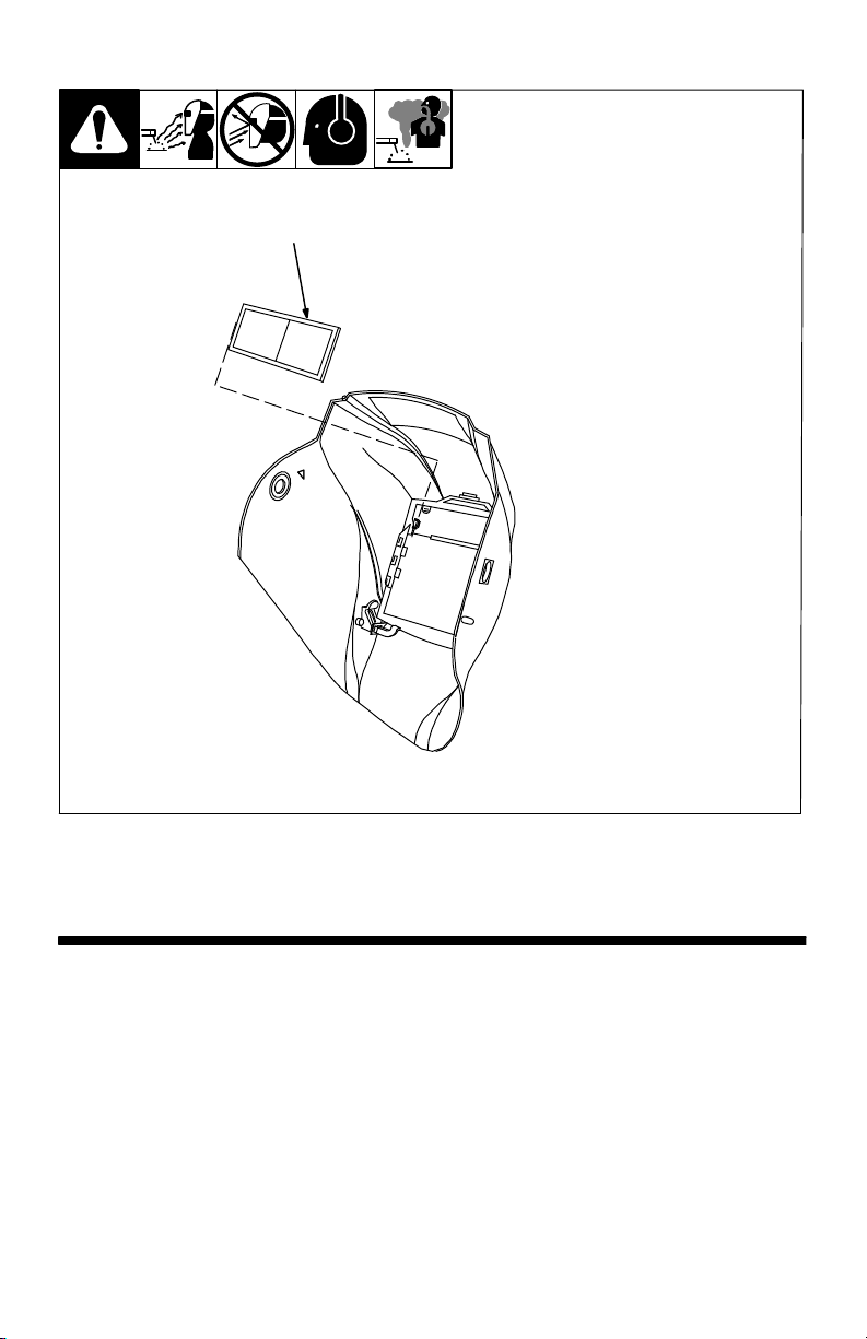
Inspect the auto-lens frequently. Immediately replace any scratched, cracked, or pitted cover
lenses or auto-lenses.
NOISE can damage hearing.
Noise from some processes or equipment can damage hearing.
Wear approved ear protection if noise level is high.
READ INSTRUCTIONS.
Read and follow all labels and the Owner’s Manual carefully before in-
stalling, operating, or servicing unit. Read the safety information at the be-
ginning of the manual and in each section.
Use only genuine replacement parts from the manufacturer.
Perform maintenance and service according to the Owner’s Manuals, industry standards,
and national, state, and local codes.
FUMES AND GASES can be hazardous.
Welding produces fumes and gases. Breathing these fumes and gases can be
hazardous to your health.
Keep your head out of the fumes. Do not breathe the fumes.
If inside, ventilate the area and/or use local forced ventilation at the arc to remove welding
fumes and gases. The recommended way to determine adequate ventilation is to sample for
the composition and quantity of fumes and gases to which personnel are exposed.
If ventilation is poor, wear an approved air-supplied respirator.
Read and understand the Safety Data Sheets (SDSs) and the manufacturer’s instructions for
adhesives, coatings, cleaners, consumables, coolants, degreasers, fluxes, and metals.
Work in a confined space only if it is well ventilated, or while wearing an air-supplied respirator.
Always have a trained watchperson nearby. Welding fumes and gases can displace air and
lower the oxygen level causing injury or death. Be sure the breathing air is safe.
Do not weld in locations near degreasing, cleaning, or spraying operations. The heat and rays
of the arc can react with vapors to form highly toxic and irritating gases.
Do not weld on coated metals, such as galvanized, lead, or cadmium plated steel, unless the
coating is removed from the weld area, the area is well ventilated, and while wearing an air-
supplied respirator. The coatings and any metals containing these elements can give off toxic
fumes if welded.

OM-235 589 Page 3
1-3. Proposition 65 Warnings
Welding or cutting equipment produces fumes or gases which contain chemicals known
to the State of California to cause birth defects and, in some cases, cancer. (California
Health & Safety Code Section 25249.5 et seq.)
This product contains chemicals, including lead, known to the state of California to cause
cancer, birth defects, or other reproductive harm. Wash hands after use.
1-4. Lens Shade Selection Table
Process Electrode Size
in. (mm)
Arc Current
in
Amperes
Minimum
Protective
Shade No.
Suggested
Shade No.
(Comfort)*
Shielded Metal Arc
Welding (SMAW)
Less than 3/32 (2.4)
3/32−5/32 (2.4−4.0)
5/32−1/4 (4.0−6.4)
More than 1/4 (6.4)
Less than 60
60−160
160−250
250−550
7
8
10
11
−−
10
12
14
Gas Metal
Arc Welding
(GMAW)
Flux Cored
Arc Welding
(FCAW)
Less than 60
60−160
160−250
250−500
7
10
10
10
−−
11
12
14
Gas Tungsten Arc
Welding (TIG)
Less than 50
50−150
150−500
8
8
10
10
12
14
Air Carbon
Arc Cutting (CAC-A)
Light
Heavy
Less than 500
500−1000
10
11
12
14
Plasma Arc
Cutting (PAC)
Less than 20
20−40
40−60
60−80
80−300
300−400
400−800
4
5
6
8
8
9
10
4
5
6
8
9
12
14
Plasma Arc Welding
(PAW)
Less than 20
20−100
100−400
400−800
6
8
10
11
6−8
10
12
14
Reference: ANSI Z49.1:2005
* Start with a shade that is too dark to see the weld zone. Then, go to a lighter shade which gives a
sufficient view of the weld zone without going below the minimum.
1-5. Principal Safety Standards
Safety in Welding, Cutting, and Allied Processes, ANSI Standard Z49.1, is available as a free down-
load from the American Welding Society at http://www.aws.org or purchased from Global Engineering
Documents (phone: 1-877-413-5184, website: www.global.ihs.com).
Safe Practice For Occupational And Educational Eye And Face Protection, ANSI Standard Z87.1,
from American National Standards Institute, 25 West 43rd Street, New York, NY 10036 (phone:
212-642-4900, website: www.ansi.org).

OM-235 589 Page 4
SECTION 2 −SPECIFICATIONS
Specification Model
Viewing Field 4 x 4 in.
(102 x 108 mm)
Lens Shade Passive (Fixed Shade) No. 10 Lens
(Upgradeable to Auto-Darkening Lens)
Total Weight 18 oz (510 g)
Standards ANSI Z87.1+(2010) and CSA
Warranty Thirty Day Limited Warranty (See Section 6)
Accessories Hard Hat Adapter
Magnifying Lens
Auto-Darkening Lens Upgrade Kit
Notes

OM-235 589 Page 5
SECTION 3 −OPERATING INSTRUCTIONS
There are four headgear ad-
justments: headgear top,
tightness, distance adjust-
ment, and angle adjustment.
1 Headgear Top Adjustment
Adjusts headgear for proper
depth on the head to ensure cor-
rect balance and stability.
2 Headgear Tightness
Adjustment
Adjusts headgear for a secure fit.
To adjust, push in the adjusting
knob located on the back of the
headgear. Turn knob left or right
to obtain desired tightness.
If adjustment is limited, it may
be necessary to remove the
comfort cushion.
3 Distance Adjustment
Adjusts the distance between the
face and the lens. To adjust, loos-
en both outside tension knobs
and press inward to free from ad-
justment slots. Move forward or
back to desired position and re-
tighten. (Both sides must be
equally positioned for proper vi-
sion.)
4 Angle Adjustment
Four pins on the right side of the
headband top provide adjustment
for the forward tilt of the helmet. To
adjust, loosen the right outside
tension adjustment knob then lift
on the control arm tab and move
it to the desired position. Retigh-
ten tension adjustment knob.
When using the back dis-
tance adjustment position,
only the back three angle ad-
justment pins can be used.
804 793
1
2
3
4
3-1. Adjusting Headgear

OM-235 589 Page 6
!Never use the helmet
without the inside
and outside lens
covers properly
installed. Welding
spatter will damage
the lens and void the
warranty.
1 Helmet Shell
2 Gasket
3 Outside Lens Cover
4 Spacer
5 Lens No. 10
6 Inside Lens Cover
7 Lens Holding Frame
To remove the lens holding
frame, push down on the
frame retaining arms and
push the retaining clips
outward. Lift the assembly
and pull free of the helmet.
To replace the outside lens
cover, push the cover to-
ward inside of helmet. Re-
move the rubber lens gas-
ket and install on new lens
cover. Reinstall the lens
holding frame.
Be sure the flat side of
lens cover gasket
faces the helmet shell.
To replace the inside lens
cover, remove the spacer
from the frame by pushing
up on the two top retaining
tabs. Replace lens cover
and reinstall the assembly
in the helmet.
7
2
1
6
5
4
3
3-2. Replacing Lens and Lens Covers
805 051

OM-235 589 Page 7
3-3. Installing Optional Magnifying Lens
1 Optional Magnifying Lens
Starting at the top, slide magnifying
lens into the helmet retaining brack-
ets. Align the magnifying lens with
the auto-darkening lens assembly.
Reverse procedure to remove
magnifying lens.
To prevent lens fogging, install
flat side of magnifying lens to-
ward auto-darkening lens.
1
SECTION 4 −MAINTENANCE
NOTICE −Never use solvents or abrasive cleaning detergents.
The helmet requires little maintenance. However, for best performance clean after each use. Using
a soft cloth dampened with a mild soap and water solution, wipe the cover lenses clean. Allow to air
dry. Occasionally, the filter lens should be cleaned by gently wiping with a soft, dry cloth.

OM-235 589 Page 8
SECTION 5 −PARTS LIST
Miller
12
7
2
1
11
8
10
9
6
5
4
3
805 051
13
Figure 5-1. MP-10 Passive Welding Helmet

OM-235 589 Page 9
Description
Part
No.
Item
No. Quantity
Figure 5-1. MP-10 Passive Welding Helmet
1♦216331 Shell, Helmet Black 1.......... ......... ..............................
1♦223454 Shell, Helmet Inferno 1.......... ......... .............................
2 216337 Gasket, Large Lens Cover 1............ ......... .........................
3 216326 Lens Cover, Frt 4-11/16 In X 5-5/8 In 1............ ......... ................
4 235629 Spacer, MP-10 1............ ......... ..................................
5 235630 Filter Plate, #10 4 1/2 X 5 1/4 (MP-10) 1............ ......... ...............
6 235628 Lens Cover, In 4-1/2 In X 5-1/4 In (MP-10) 1............ ......... ...........
7 216335 Frame, Lens Holding Top Cntrl 1............ ......... .....................
8 770246 Ratchet Headgear Assy 1............ ......... ...........................
9 770248 Adjustment Hardware 1............ ........... ..........................
10 770249 Fabric Headband 1........... ........... ..............................
079975 O-ring, 0.187 ID X 0.103 CS Rbr 2.............. ......... ...................
11 ♦216336 Cushion 1......... ......... ........................................
12 ♦770250 Bag, Miller 1......... ......... ......................................
♦222003 Adapters, Hard Hat (Not Shown) 1............ ......... ...................
♦259637 Adapters, Slotted Hard Hat (Not Shown) 1............ ......... .............
13 ♦212235 Lens, 0.75 Magnification 1......... ......... ..........................
13 ♦212236 Lens, 1.00 Magnification 1......... ......... ..........................
13 ♦212237 Lens, 1.25 Magnification 1......... ......... ..........................
13 ♦212238 Lens, 1.50 Magnification 1......... ......... ..........................
13 ♦212239 Lens, 1.75 Magnification 1......... ......... ..........................
13 ♦212240 Lens, 2.00 Magnification 1......... ......... ..........................
13 ♦212241 Lens, 2.25 Magnification 1......... ......... ..........................
13 ♦212242 Lens, 2.50 Magnification 1......... ......... ..........................
♦236052 Kit, Digital Elite Auto-Darkening Lens Upgrade 1............ ......... ........
♦Optional
SECTION 6 −LIMITED WARRANTY
LIMITED WARRANTY – Subject to the terms and conditions below. Miller Electric
Mfg. Co., Appleton, Wisconsin, warrants to its original retail purchaser that the new
Miller equipment sold after the effective date of this limited warranty is free of defects
in material and workmanship at the time it is shipped by Miller. THIS WARRANTY
IS EXPRESSLY IN LIEU OF ALL OTHER WARRANTIES, EXPRESS OR IMPLIED,
INCLUDING THE WARRANTIES OR MERCHANTABILITY AND FITNESS.
Miller fixed shade helmets are warranted for 30 days from the date of purchase.
Proof of purchase is required for warranty transactions so it is imperative that a copy
of the original invoice or sales receipt be retained.
For warranty transactions, contact your Miller Distributor.
Effective January 1, 2015

ORIGINAL INSTRUCTIONS ©2015 Miller Electric Mfg. Co.
Visit our website at
www.MillerWelds.com
®
Miller Electric Mfg. Co.
An Illinois Tool Works Company
1635 West Spencer Street
Appleton, WI 54914 USA
Table of contents
Other Miller Motorcycle Accessories manuals

Miller
Miller Titanium Series User manual

Miller
Miller Elite Series User manual

Miller
Miller T94 Series User manual

Miller
Miller Titanium Series User manual

Miller
Miller Elite Series User manual

Miller
Miller Digital Performance Series User manual

Miller
Miller Elite Series User manual

Miller
Miller Digital Elite User manual

Miller
Miller AirArmor User manual

Miller
Miller Pro-Hobby Series User manual