Milwaukee HEAVY DUTY M12 CLL4P User manual

EN Original instructions
DE Originalbetriebsanleitung
FR Notice originale
IT Istruzioni originali
ES Manual original
PT Manual original
NL Oorspronkelijke gebruiksaanwijzing
DA Original brugsanvisning
NO Original bruksanvisning
SV Bruksanvisning i original
FI Alkuperäiset ohjeet
EL Πρωτότυπο οδηγιών χρήσης
TR Orijinal işletme talimatı
CS Původním návodem k používání
click
click
click
click
click
click
click
click
click
click
click
click
click
click
M12 CLL4P

1
ENGLISH
WARNING:
Avoid direct eye exposure. The laser beam can cause severe eye damage and/or blindness.
Do not stare into the laser beam or direct it towards other people unnecessarily.
Caution! The laser emitting product may be behind you in some applications. Be careful when facing the product.
WARNING:
Do not operate the laser around children or allow children to operate the laser.
The reective surface could reect the beam back at the operator or other persons.
WARNING: Use of controls, adjustments, or the performance of procedures other than those specied in the manual
may result in hazardous radiation exposure.
When the laser is brought into a warm environment from very cold conditions, or vice versa, allow it to come to the
surrounding temperature before use.
Always store the cross laser indoors, avoid substantial knocks, continuous vibration or extreme temperatures.
Always keep the tool away from dust, liquids and high humidity. These may damage internal components or aect
accuracy.
If laser radiation hits your eye, you must close your eyes and immediately turn your head away from the beam.
Do not position the laser beam so that it unintentionally blinds you or others.
Do not look into a laser beam using magnifying optical devices such as binoculars or a telescope, as this will increase
the level of eye injury.
If you use laser goggles to enhance the visibility of the laser beam, please notice that they will not protect your eyes
against laser radiation.
Do not remove or deface warning labels on the laser level.
Do not disassemble the laser level, laser radiation can cause serious eye injury.
When not in use, turn o the power, engage the pendulum lock and place the laser in its carrying pouch.
Make sure the pendulum lock mechanism is engaged before transporting the laser.
Note: If the pendulum lock mechanism is not engaged before transportation, internal mechanical damage may occur.
Do not use aggressive cleaning agents or solutions. Use only a clean, soft cloth for cleaning.
Avoid heavy impact to or dropping of the laser. The accuracy of the laser should be checked before use if it has been
dropped or subjected to other mechanical stresses.
Any repair required on this laser product should be performed only by authorised service personnel.
Do not operate the product in explosion hazardous areas or in aggressive environments.
If the laser level is not in use for a long period of time, remove the batteries from the battery compartment. This will
prevent batteries from leaking and corrosion damage.
Do not dispose of waste batteries, waste electrical and electronic equipment as unsorted municipal waste.
Waste batteries and waste electrical and electronic equipment must be collected separately.
Waste batteries, waste accumulators and light sources have to be removed from equipment.
Check with your local authority or retailer for recycling advice and collection point.
According to local regulations retailers may have an obligation to take back waste batteries and Waste electrical and
electronic equipment free of charge.
Your contribution to re-use and recycling of waste batteries and waste electrical and electronic equipment helps to
reduce the demand of raw materials.
Waste batteries, in particular containing lithium and waste Electrical and electronic equipment contain valuable,
recyclable materials, which can adversely impact the environment and the human health, if not disposed of in an
environmentally compatible manner.
Delete personal data from waste equipment, if any.
European Conformity Mark
British Confomity Mar
k
I
mportant safety instructions ......................................................................................................................1
Maintenance ............................................................................................................................................... 2
Technical data............................................................................................................................................. 2
Specic conditions of use ........................................................................................................................... 2
Overview..................................................................................................................................................... 3
Accessory ................................................................................................................................................... 4
Change batteries ........................................................................................................................................ 4
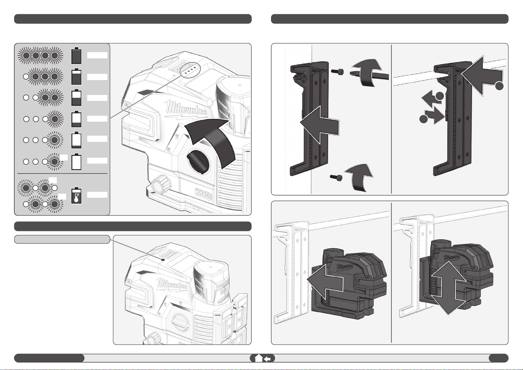
Fuel gauge.................................................................................................................................................. 5
Power Save ................................................................................................................................................ 5
Track clip .................................................................................................................................................... 5
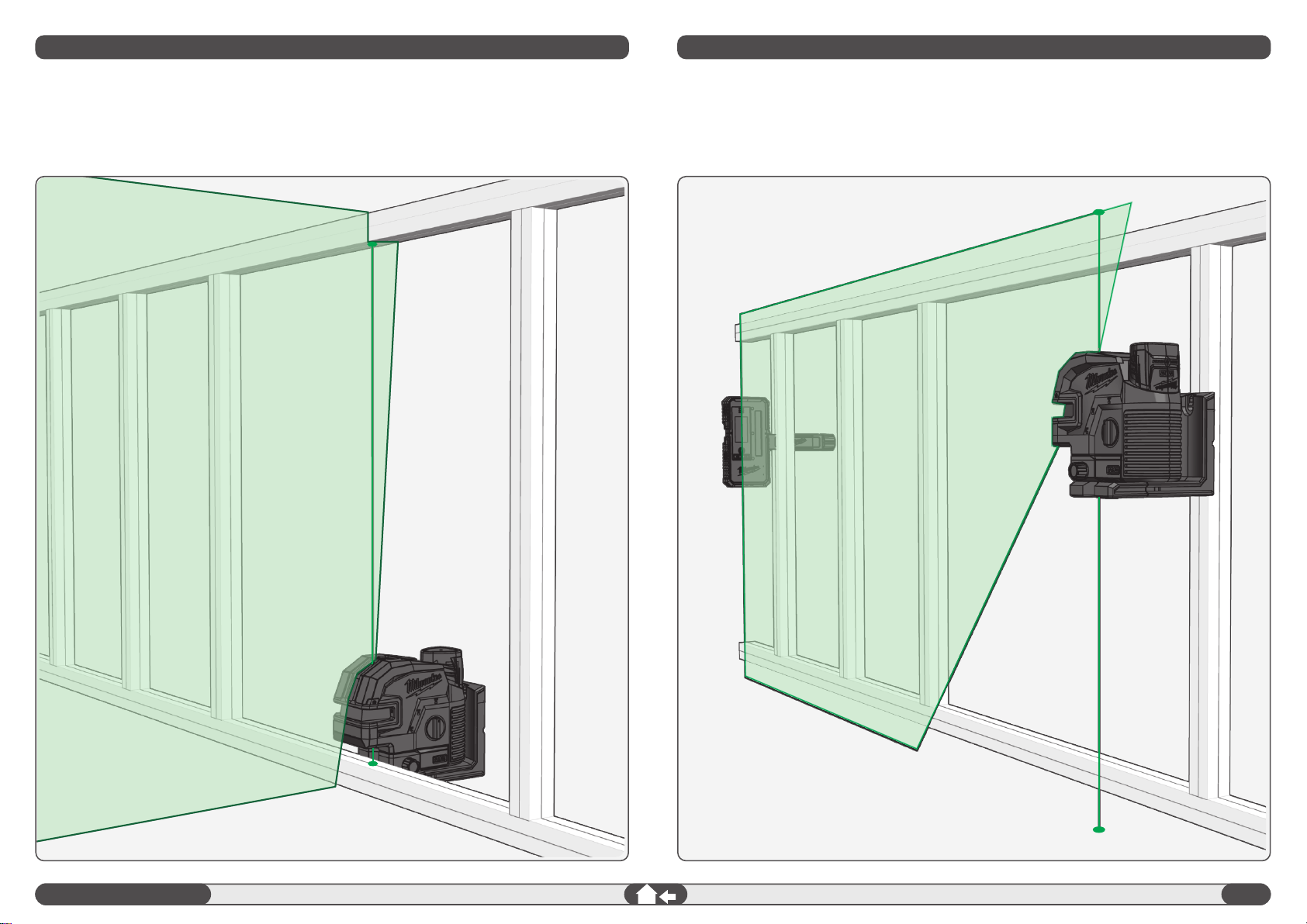
Magnetic Wall mount ..................................................................................................................................6
Green Target Plate ..................................................................................................................................... 6
Tripod Mount ..............................................................................................................................................6
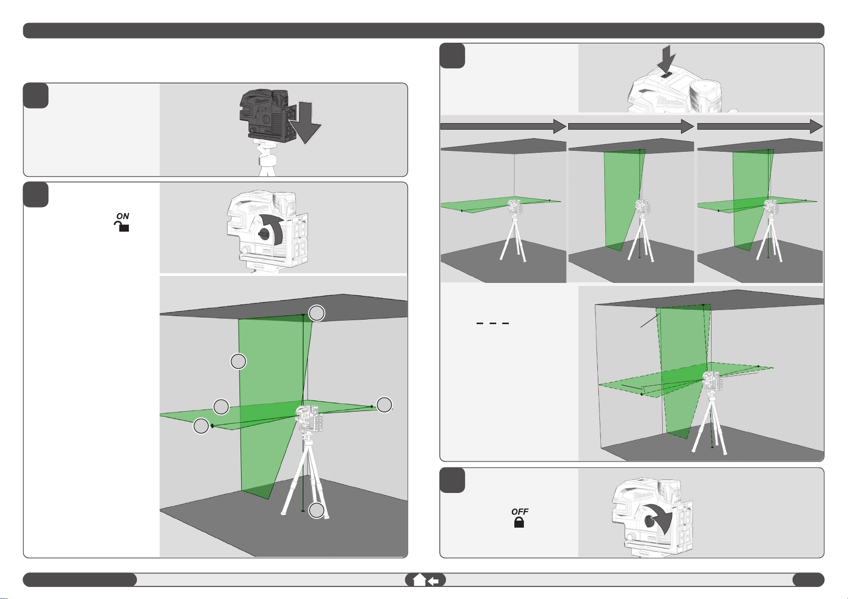
Working in self-leveling mode ..................................................................................................................... 7
Working in manual mode ............................................................................................................................ 8
Plumb function ............................................................................................................................................ 9
Detector ...................................................................................................................................................... 9
Accuracy check ........................................................................................................................................ 10
CONTENTS
I
MPORTANT SAFETY INSTRUCTIONS
CAUTION! WARNING! DANGER!
Do not use the product before you have studied the Safety instructions and the User Manual.
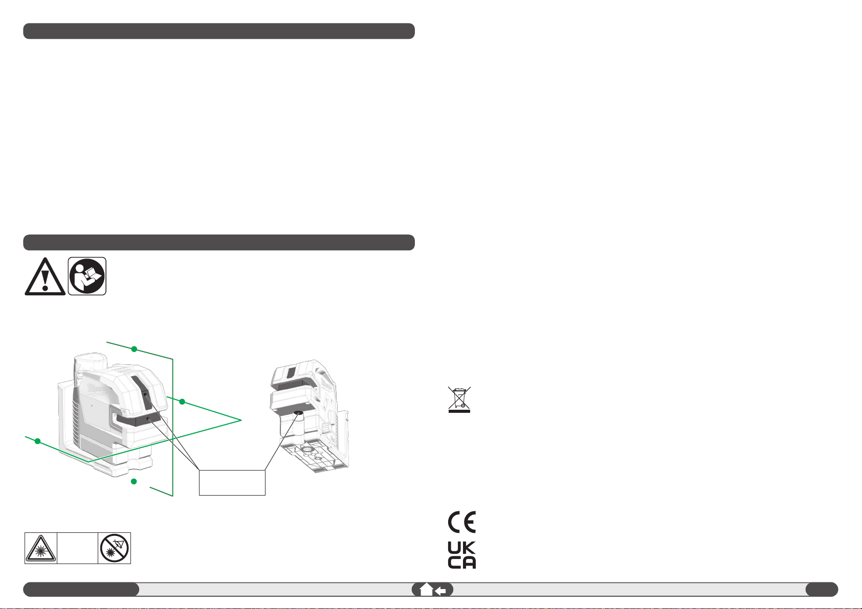
Laser Classication
Laser Beam
outlet aperture
WARNING:
It is a Class 2 laser product in accordance
with EN60825-1:2014 .
LASER
2

2
ENGLISH
MAINTENANCE
Wipe the aperture lens and the body of the cross laser with a clean soft cloth. Do not use solvents.
Although the cross laser is dust and dirt resistant to a certain degree, do not store in dusty places as long
term exposure may damage internal moving parts.
If the cross laser is exposed to water, dry the laser level before returning it to the carrying case to prevent
corrosion damage.
TECHNICAL DATA
Laser class 2
Self-leveling range ± 4°
Self-leveling time ≤ 3 s
Battery technology Li-Ion
Voltage DC 12 V
Protection class (water and dust
protection) IP54*
Max. altitude 2000 m
Relativ air humidity max. 80%
Pollution degree according to
IEC 61010-1 2**
Pulse duration tPNornal mode ≤ 80 µs
Power save ≤ 50 µs
Functions Horizontal level line & horizontal points
Vertical plumb line & plumb points
Perpendicular level, plumb points & horizontal points
Frequency 10 kHz
Projections 2 lines green, 4 points green
Diode quantity 2
Diode type 50 mW
Laser beams output pattern Single horizontal level line + 2 horizontal points (left & right);
Single vertical plumb line + 2 plump points (up & down);
Cross line + 2 horizontal points + 2 plump points.
Operating time 9 hrs (normal mode) / 16 hrs (power save mode) with M12
3.0 Ah Battery
Tripod mount 1/4" / 5/8" thread
Suitable detector Milwaukee LLD50, LRD100
Laser Line
Width < 11.12mm @ 38"
Wavelength 510 - 530 nm laser class II
Max. power ≤ 7 mW
Accuracy +/- 3 mm / 10 m
Beam divergence 1 rad
Fan angle vertical line > 150°; horizontal line > 180°
Colour green
Working range
38 m (with detector LLD50 50 m, with detector LRD100 100 m)
Laser points Laser point wavelength 510 - 530 nm laser class II
Laser point max. power < 1 mW
Plumb accuracy +/- 3 mm / 10 m
Points beam divergence 0.5 mrad
Laser point colour green
Working range
38 m
Recommended ambient operating
temperature -20°C - +40 °C
Storage temperature -20°C - +65 °C
Recommended battery types M12 B...
Dimensions 171 x 82 x 150 mm
Weight (incl. battery) 1262 g
* The Lithium-ion battery and the battery compartment are excluded from IP 54.
** Only non-conductive deposits occur, whereby occasional temporary conductivity caused by
condensation is expected.
SPECIFIC CONDITIONS OF USE
The laser is innovatively designed for a very broad range of professional jobs, including:
-Aligning tiles, marble, cabinets, borders, moldings and trimmings
-Marking layout for doors, windows, rails, stairs, fences, gates, decks and pergolas installation.
-It is intended for determining and checking horizontal and vertical lines.
-Levelling suspended ceilings, Levelling pipe installations, Window partitioning and pipe alignment, laying
out perimeter walls for electric installations.
Do not use this product in any other way as stated for normal use.

3
ENGLISH
Horizontal laser beam & horizontal points (left
and right) window
Mode button
Short press: choose between beams:
- horizontal level line + horizontal points
- vertical plumb line + plumb points
- perpendicular level + plumb points + horizontal points
Long press: switch normal mode / power save mode
Vertical laser beam & plumb point up window
Plumb spot down
1/4" tripod mount
5/8" tripod mount
OVERVIEW
Track clip
20° micro adjustment (+/-10° from center)
M12 Battery
LED indicator fuel gauge
Marking for the horizontal beam
Rotation dial
O / locked
On / manual mode
On / self leveling mode
Magnetic mount
Power save indicator

4
ENGLISH
CHANGE BATTERIES
Change the batteries when the laser beams begin to dim.
If the cross laser is not in use for a long period of time, remove the batteries from the battery
compartment. This will prevent batteries from leaking and corrosion damage.
ACCESSORY
Not included in standard equipment, available as an accessory.
click
1
2

5
ENGLISH
POWER SAVE
FUEL GAUGE
After switch on the laser the fuel gauge will display the battery life
4x
4x
4x
66-100%
45-65%
18-44%
8-17%
<7%
0%
> 40°C
Use power save mode to extend the
battery run time. Power save mode is
indicated by dimmed laser beams and
the power save indicator pulsing. Visual
range is decreased in power save mode.
Power save indicator will change from
pulsing to solid Green when turned OFF.
The tool will automatically switch to
power save mode if less than 7% of
battery charge remains.
TRACK CLIP
Fix the track clip with screws to a pillar. Or clamp the track clip to ceiling channels,
racks....
Power save indicator
2
3
1

6
ENGLISH
MAGNETIC WALL MOUNT
TRIPOD MOUNT
Use the tripod mount to x the laser on a tripod
Tripod mount 1/4"
GREEN TARGET PLATE
Use the green target plate to improve visibility of the laser beam in unfavourable conditions and at greater
distances.
Turn the laser 360°. Use the adjustment knob for 20° pivot micro
adjustment
Use the magnetic wall mount to x the laser to a
wall or metallic structures or similar.
Or x it with a screw or nail on a pillar
Tripod mount 5/8"

7
1
3
4
2
ENGLISH
> 4°
> 4°
WORKING IN SELF-LEVELING MODE
In self-leveling mode the cross laser will level itself in a ± 4° range and can project a horizontal beam and
horizontal points, a vertical beam line and plumb points or a both beams together with plumb points and
horizontal points
Place the cross laser on a solid at
vibration free surface or on a tripod.
Turn the rotation dial to:
position
The cross laser can generate
2 laser beams and 4 laser points.
(A) horizontal beam forward
(B) vertical beam forward
(C) plumb points
(D) horizontal points
The cross laser will generate
forward cross beams including
4 laser points when all beams are
activated.
Choose the beams that you want to
work with by pushing the MODE
button
If the initial level of the cross laser
is beyond ± 4° and the self-leveling
mode is activated, the laser beams
will ash
In this case reposition the cross
laser.
Before moving the cross laser, turn
the rotation dial to: .
This will lock the pendulum and
protect your cross laser.
1/4" male thread
5/8" male thread
A
DD
C
C
B

8
1
3
4
2
ENGLISH
WORKING IN MANUAL MODE
In manual mode the cross lasers self-leveling mechanism is disabled and the laser lines can be set at
any slope required.
Place the cross laser on a solid at
vibration free surface or on a tripod.
Turn the rotation dial to:
position.
Same as in the self-leveling mode,
but the laser beams are
interrupted every 8 seconds.
8 sec. 8 sec. 8 sec.
To turn the Manual mode o,
turn the rotation dial to: .
or
turn the rotation dial to:
Tilt the laser using a tripod and adjust
to the desired angle and height.
Choose the beams that you want to
work with by pushing operation push
button

9
ENGLISH
PLUMB FUNCTION
With the plumb function, a point on the oor and on the ceiling can be projected.
Use the plumb function e.g. to transfer reference point for light installation, vents, transfer of heights.
DETECTOR
For outdoor work under direct sunlight, or bright conditions and for extended indoor ranges of up to 50
meters / 164 feet, use the Milwaukee detector.
A detector is not included and must be purchased separately.
For information on how to operate the detector, please refer to the operating instructions for the detector.

10
1. Set up the laser on a tripod or on a at surface
between two walls A and B, approximately 10 meters apart.
2. Position the laser level approximately 0.5 meter from wall A.
3. Switch ON the self-leveling mode and press the mode button to project the horizontal and the vertical
cross beams towards wall A.
4. Mark the center of the cross beams on the wall as a1.
A
a2
a1
180°
180°
B
A
a1
a1
a1
≈ 10 m
5 m
0,5 m
0,5 m
b1
b1, b2
b1, b2
B
A B
a1
a2
a1
A
B
a1
b
a2
b
a1
180°
a1
b1
A
B
a2
a1
b2
b1
A
C
B
a2
a1
5. Turn the laser 180° towards wall B and mark the center of the cross beams as b1 on the wall.
A
a2
a1
180°
180°
B
A
a1
a1
a1
≈ 10 m
5 m
0,5 m
0,5 m
b1
b1, b2
b1, b2
B
A B
a1
a2
a1
A
B
a1
b
a2
b
a1
180°
a1
b1
A
B
a2
a1
b2
b1
A
C
B
a2
a1
6. Move the laser level towards wall B and position it approximately 0.5 meter from wall B.
7. Mark on wall B the center of the cross beams as b2.
If the b1 & b2 is not overlapping, adjust the tripod height to make sure b1& b2 overlapping.
A
a2
a1
180°
180°
B
A
a1
a1
a1
≈ 10 m
5 m
0,5 m
0,5 m
b1
b1, b2
b1, b2
B
A B
a1
a2
a1
A
B
a1
b
a2
b
a1
180°
a1
b1
A
B
a2
a1
b2
b1
A
C
B
a2
a1
8. Turn the laser 180° towards wall A, and mark on the wall the center of the cross beams
as a2.
A
a2
a1
180°
180°
B
A
a1
a1
a1
≈ 10 m
5 m
0,5 m
0,5 m
b1
b1, b2
b1, b2
B
A B
a1
a2
a1
A
B
a1
b
a2
b
a1
180°
a1
b1
A
B
a2
a1
b2
b1
A
C
B
a2
a1
9. Measure the distances:
Δa= |a2 - a1|
10. Δa should be no more than 6 mm.
ENGLISH
ACCURACY CHECK
This cross laser left the factory fully calibrated. Milwaukee recommends the user to check the accuracy of
the laser periodically, especially if the unit falls or is mishandled.
If the maximum deviation of the laser is exceeded in one of the accuracy checks, please contact one of
our Milwaukee service agents (see our list of guarantee/service addresses).
1. Checking the height accuracy of the horizontal beam.
2. Checking the leveling accuracy of the horizontal beam.
3. Checking the leveling accuracy of the vertical beam.
4. Checking Plumb accuracy
5. Squaring
CHECKING THE HEIGHT ACCURACY OF THE HORIZONTAL BEAM
(UP AND DOWN DEVIATION)
Before checking the laser accuracy, after mounting the laser on the tripod, check the leveling of the
tripod.
1

11
For this check, a free surface of approx. 10 x 10 meters is required.
1. Set up the laser on a tripod or on a solid surface between two walls A and B, approximately 5 meters
apart.
2. Position the laser level approximately 5 meters from the center of the room.
3. Switch ON the self-leveling mode and press the mode button to project the horizontal line towards
wall A and B.
4. Mark the center of the laser line point a1 on wall A and point b1 on wall B.
A
a2
a1
180°
180°
B
A
a1
a1
a1
≈ 10 m
5 m
0,5 m
0,5 m
b1
b1, b2
b1, b2
B
A B
a1
a2
a1
A
B
a1
b
a2
b
a1
180°
a1
b1
A
B
a2
a1
b2
b1
A
C
B
a2
a1
5. Move the laser level approximately 10 meters away and turn the laser 180° towards wall A and B.
6. Mark the center of the laser line point a2 on wall A and point b2 on wall B.
A
a2
a1
180°
180°
B
A
a1
a1
a1
≈ 10 m
5 m
0,5 m
0,5 m
b1
b1, b2
b1, b2
B
A B
a1
a2
a1
A
B
a1
b
a2
b
a1
180°
a1
b1
A
B
a2
a1
b2
b1
A
C
B
a2
a1
7. Measure the distances:
Δa= |a2- a1|
Δb= |b1- b2|
8. The dierence | Δa – Δb| should be no more than 6 mm
ENGLISH
CHECKING THE LEVEL ACCURACY OF THE HORIZONTAL BEAM (SIDE TO SIDE INCLINATION)
2

12
1. Hang an approximately 2 m plumb line on
a wall.
2. After the plumb line has settled, mark
point a1 on the wall, behind the plumb
line, near the plumb cone.
A
a2
a1
180°
180°
B
A
a1
a1
a1
≈ 10 m
5 m
0,5 m
0,5 m
b1
b1, b2
b1, b2
B
A B
a1
a2
a1
A
B
a1
b
a2
b
a1
180°
a1
b1
A
B
a2
a1
b2
b1
A
C
B
a2
a1
A
a2
a1
180°
180°
B
A
a1
a1
a1
≈ 10 m
5 m
0,5 m
0,5 m
b1
b1, b2
b1, b2
B
A B
a1
a2
a1
A
B
a1
b
a2
b
a1
180°
a1
b1
A
B
a2
a1
b2
b1
A
C
B
a2
a1
3. Set up the cross laser on a tripod or on a
at surface in front of the wall at a
distance of approximately 2.5 m.
4. Switch ON the self-leveling mode, and
press the mode button to project the
vertical beam towards the plumb line.
5. Turn the laser so that the vertical beam
will merge with the plumb line below the
hanging point.
6. Mark point a2 on the wall, in the middle of
the vertical beam at the same height as
a1.
7. The distance between a1 and a2, should
be no more than 0.75 mm
A
a2
a1
180°
180°
B
A
a1
a1
b2
a1
≈ 5 m
5 m
0,5 m
0,5 m
b1
b1
b2
B
A B
2 m
a1
a2
a1
b1
A
B
a1
b
a2
b
a1
180°
a1
b1
A
B
a2
a1
b2
b1
A
a2
a1
180°
180°
B
A
a1
a1
b2
a1
≈ 5 m
5 m
0,5 m
0,5 m
b1
b1
b2
B
A B
2 m
a1
a2
a1
b1
A
B
a1
b
a2
b
a1
180°
a1
b1
A
B
a2
a1
b2
b1
ENGLISH
CHECKING PLUMB ACCURACY
CHECKING THE LEVEL ACCURACY OF THE VERTICAL BEAM
3 4
This procedure requires a room of with
approx. 5m distance between oor and
ceiling.
1. Set up the cross laser on a tripod.
2. Switch ON the self-leveling mode
and press the mode button to
switch to the plump function.
3. Mark the upper plumb dot on the
ceiling as point a1 (see the
illustration).
4. Mark the lower plumb dot on the
oor as point b.
5. Rotate the laser level 180°, position
it so that the center of the plumb
dot is on the point b, which has
already been marked, and allow it
to level.
6. Mark the center of the upper plumb
dot on the ceiling as point a2.
7. The distance between points a1
and a2 marked on the ceiling is an
indication of the actual deviation of
the laser level from the ideal plumb
line.
If the measuring distance is 5m,
the maximum permissible deviation
is:
5 m x (+/- 0.3 mm/m) x 2 = +/ - 3 mm.
8. The distance between a1 and a2,
should not be more than 6 mm.

13
ENGLISH
SQUARING PROCEDURE
5
1. Mark a reference (point x) on the oor that
is equidistant from each wall in the center
of a room.
2. Turn ON the laser and switch to the
"Unlocked" position. Ensure that laser is
in Perpendicular Level, Plumb Points, and
Horizontal Points mode (all lasers ON).
3. Using the down plumb point, align the
laser directly over the center of point (x)
on the oor.
4. With the laser in place, mark point (I) at
the intersection of the lines directly in front
of the laser on wall A. Without moving the
laser, also mark the center of the right
Horizontal point (II) on wall B.
5. Rotate the laser 90 degrees clockwise
around plumb point (x) and align the left
Horizontal dot with the previously marked
point I.
6. With the laser in position, mark point (III)
on wall B at the intersection of the
perpendicular lines directly in front of the
laser. Without moving the laser, mark point
(IV) on wall C using the right horizontal
point.
7. The deviation (d) between points II & III
should be no more than 3 mm at 10 m .
8. Lastly, rotate the laser 180º clockwise
around plumb point (x) so that the right
horizontal point is aligned with the
previously marked point I. Without
moving the laser, using the left horizontal
point mark (V) on wall C.
9. The deviation (d) between points IV & V
should be no more than 3 mm at 10 m.

1
DEUTSCH
Warnung:
Die Augen nicht direkt dem Laserstrahl aussetzen. Der Laserstrahl kann schwerwiegende Augenschäden und/oder Erblinden
verursachen.
Nicht direkt in den Laserstrahl blicken und den Strahl nicht unnötigerweise auf andere Personen richten.
Vorsicht! Bei einigen Anwendungen kann sich das laseremittierende Gerät hinter Ihnen benden. Wenden Sie sich in diesem
Fall vorsichtig um.
Warnung: Betreiben Sie den Laser nicht in Gegenwart von Kindern und erlauben Sie ihnen auf keinen Fall, den Laser zu
benutzen.
Achtung! Eine reektierende Oberäche kann den Laserstrahl zurück an den Bediener oder andere Personen reektieren.
Warnung: Die Verwendung von Steuerelementen, Einstellungen oder die Durchführung von anderen als den im Handbuch
festgelegten Verfahren kann zu gefährlicher Strahlenbelastung führen.
Wird der Laser von einer sehr kalten in eine warme Umgebung (oder umgekehrt) gebracht, muss es vor Gebrauch die
Umgebungstemperatur erreichen.
Den Laser nicht im Freien aufbewahren und vor Schlägen, dauerhaften Vibrationen und extremen Temperaturen schützen.
Den Laser vor Staub, Nässe und hoher Luftfeuchtigkeit schützen. Andernfalls können innere Bauteile beschädigt oder die
Genauigkeit beeinusst werden.
Falls Laserstrahlung ins Auge trit, die Augen schließen und den Kopf sofort aus dem Strahl wegdrehen.
Achten Sie darauf, den Laserstrahl so zu positionieren, dass Sie selbst oder andere Personen davon nicht geblendet werden.
Nicht mit optischen Vergrößerungsgeräten, wie Ferngläsern oder Teleskopen, in den Laserstrahl blicken. Andernfalls erhöht
sich die Gefahr von schwerwiegenden Augenschäden.
Beachten Sie, dass Lasersichtbrillen zum besseren Erkennen der Laserlinien dienen, die Augen jedoch nicht vor
Laserstrahlung schützen.
Warnschilder auf dem Lasergerät dürfen nicht entfernt oder unkenntlich gemacht werden.
Den Laser nicht auseinanderbauen. Laserstrahlung kann schwere Augenverletzungen verursachen.
Bei Nichtgebrauch den Laser ausschalten, die Pendelsperre arretieren und den Laser ins seiner Tragetasche verstauen.
Vor dem Transport des Lasers sicherstellen, dass die Pendelarretierung eingerastet ist.
Hinweis: Bei nicht eingerasteter Pendelarretierung kann es während des Transports zu Beschädigungen im Inneren des Geräts
kommen.
Keine aggressiven Reinigungsmittel oder Lösungsmittel verwenden. Nur mit einem sauberen, weichen Tuch reinigen.
Den Laser vor heftigen Stößen und Stürzen schützen. Nach einem Sturz oder starken mechanischen Einwirkungen ist die
Genauigkeit des Geräts vor Gebrauch zu überprüfen.
Erforderliche Reparaturen an diesem Lasergerät dürfen nur von autorisiertem Fachpersonal durchgeführt werden.
Das Produkt darf nicht in einer explosionsgefährdeten oder aggressiven Umgebung eingesetzt werden.
Vor längerem Nichtgebrauch des Geräts die Batterien aus dem Batteriefach entnehmen. So lassen sich das Auslaufen der
Batterien und damit verbundene Korrosionsschäden vermeiden.
Altbatterien, Elektro- und Elektronik-Altgeräte dürfen nicht zusammen mit dem Hausmüll entsorgt werden. Altbatterien,
Elektro- und Elektronik-Altgeräte sind getrennt zu sammeln und zu entsorgen.
Entfernen Sie Altbatterien, Altakkumulatorn und Leuchtmittel vor dem Entsorgen aus den Geräten.
Erkundigen Sie sich bei den örtlichen Behörden oder bei Ihrem Fachhändler nach Recyclinghöfen und Sammelstellen.
Je nach den örtlichen Bestimmungen können Einzelhändler verpichtet sein, Altbatterien, Elektro- und Elektronik-Altgeräte
kostenlos zurückzunehmen.
Tragen Sie durch Wiederverwendung und Recycling Ihrer Altbatterien, Elektro- und Elektronik-Altgeräte dazu bei, den Bedarf
an Rohmaterialien zu verringern.
Altbatterien (vor allem Lithium-Ionen-Batterien), Elektro- und Elektronik-Altgeräte enthalten wertvolle, wiederverwertbare
Materialien, die bei nicht umweltgerechter Entsorgung negative Auswirkungen auf die Umwelt und Ihre Gesundheit haben
können.
Löschen Sie vor der Entsorgung möglicherweise auf Ihrem Altgerät vorhandene personenbezogene Daten.
CE-Zeichen
Britisches Konformitätszeichen
Wichtige Sicherheitshinweise ..................................................................................................................... 1
Wartung ......................................................................................................................................................2
Technische Daten ....................................................................................................................................... 2
Bestimmungsgemäße Verwendung............................................................................................................ 2
Übersicht .................................................................................................................................................... 3
Zubehör ..................................................................................................................................................... 4
Akku wechseln ........................................................................................................................................... 4
Fuel Gauge ................................................................................................................................................. 5
Stromsparmodus ........................................................................................................................................ 5
Deckenbefestigung .................................................................................................................................... 5
Magnetische Wandhalterung ......................................................................................................................6
Grüne Zieltafel ............................................................................................................................................ 6
Stativgewinde ............................................................................................................................................. 6
Arbeiten im Selbstnivelliermodus ............................................................................................................... 7
Arbeiten im manuellen Modus .................................................................................................................... 8
Lotfunktion .................................................................................................................................................. 9
Detektor ...................................................................................................................................................... 9
Genauigkeit überprüfen ............................................................................................................................ 10
INHALT
WICHTIGE SICHERHEITSHINWEISE
ACHTUNG! WARNUNG! GEFAHR!
Nehmen Sie das Produkt erst in Gebrauch, wenn Sie die Sicherheitshinweise und die
Gebrauchsanweisung gelesen haben.
Laserklassizierung
Laserstrahlaustritts-
önung
WARNUNG:
Das Produkt entspricht der Laserklasse 2 gemäß EN60825-1:2014 .
LASER
2

2
DEUTSCH
WARTUNG
Das Objektiv und das Gehäuse des Lasers mit einem weichen, sauberen Tuch reinigen. Keine
Lösungsmittel verwenden.
Auch wenn der Laser bis zu einem gewissen Grad staub- und schmutzbeständig ist, sollte er nicht
längerfristig an einem staubigen Ort aufbewahrt werden, da andernfalls innenliegende bewegliche Teile
beschädigt werden können.
Sollte der Laser nass werden, ist es vor dem Einsetzen in den Tragekoer zu trocknen, damit keine
Rostschäden entstehen.
TECHNISCHE DATEN
Laserklasse 2
Selbstnivellierungsbereich ± 4°
Selbstnivellierungsdauer ≤ 3 s
Batterietyp Li-Ion
Spannung DC 12V
Schutzart (Spritzwasser und Staub) IP54*
Max. Höhenlage 2000 m
Relative Luftfeuchtigkeit max. 80%
Verschmutzungsgrad nach IEC 61010-1 2**
Pulsdauer tPNormalbetrieb ≤ 80 µs
Stromsparmodus ≤ 50 µs
Funktionen Horizontale Laserlinie + horizontal projizierte Punkte
Vertikale Lotrechte + lotrecht projizierte Punkte
Lotrechte Ebene, lotrecht + horizontal projizierte Punkte
Frequenz 10 kHz
Projektionen 2 grüne Linien, 4 grüne Punkte
Anzahl Dioden 2
Diodentyp 50 mW
Laserlinienausgabemuster Einfache horizontale Laserlinie + 2 horizontal projizierte
Punkte (links & rechts);
Einfache vertikale Lotrechte + 2 lotrecht projizierte Punkte
(oben & unten);
Kreuzlinie + 2 horizontal projizierte Punkte + 2 lotrecht
projizierte Punkte.
Betriebszeit 9 Std. (Normalbetrieb) / 16 Std. (Stromsparmodus) mit Akku
M12, 3,0 Ah
Stativgewinde 1/4“ / 5/8“
Geeigneter Detektor Milwaukee LLD50, LRD100
Laserlinie Breite < 11,12 mm @ 38“
Wellenlänge 510 - 530 nm Laserklasse II
Maximale Leistung ≤ 7 mW
Genauigkeit +/- 3 mm / 10 m
Laserstrahlabweichung 1 rad
Önungswinkel Vertikale Linie > 150°; Horizontale Linie > 180°
Farbe grün
Reichweite
38 m (mit Detektor LLD50 50 m, mit Detektor LRD100 100 m)
Laserpunkte Wellenlänge Laserpunkt 510 - 530 nm Laserklasse II
Max. Leistung Laserpunkt < 1 mW
Lotgenauigkeit +/- 3 mm / 10 m
Laserpunktabweichung 0,5 rad
Laserpunktfarbe grün
Reichweite
38 m
Empfohlene Betriebstemperatur -20 °C bis +40 °C
Lagertemperatur -20 °C bis +65 °C
Empfohlene Akkutypen M12 B...
Abmessungen 171 mm x 82 mm x 150 mm
Gewicht (inkl. Batterien) 1262 g
* Der Lithium-ion Akku und das Akkufach sind von IP54 ausgeschlossen.
** Es tritt nur eine nicht leitfähige Verschmutzung auf, wobei jedoch gelegentlich eine vorübergehende
durch Betauung verursachte Leitfähigkeit erwartet wird.
BESTIMMUNGSGEMÄSSE VERWENDUNG
Dieser innovative Laser ist für einen breiten professionellen Anwendungsbereich ausgelegt, wie z. B.:
-Ausrichten von Fliesen, Marmorplatten, Schränken, Bordüren, Formteilen und Besätzen
-Markieren der Grundlinien für den Einbau von Türen, Fenstern, Schienen, Treppen, Zäunen, Toren,
Veranden und Pergolen.
-Für die Bestimmung und Prüfung von horizontalen und vertikalen Linien.
-Nivellieren von abgehängten Decken und Rohrleitungen, Fensteraufteilung und Rohrausrichtung,
Nivellieren von Umfassungswänden für Elektroinstallationen
Dieses Produkt darf nur wie angegeben bestimmungsgemäß verwendet werden.

3
DEUTSCH
Fenster für horizontalen Laserstrahl +
horizontal projizierte Punkte (links & rechts)
Modustaste
Kurzes Drücken: Wählen Sie zwischen Laserlinien:
- Horizontale Laserlinie + horizontal projizierte Punkte
- Vertikale Lotrechte + lotrecht projizierte Punkte
- Lotrechte Ebene + lotrecht + horizontal projizierte Punkte
Langes Drücken: Umschalten Normalmodus /
Energiesparmodus
Fenster für vertikalen Laserstrahl + lotrecht
projizierten Punkt oben
Lotpunkt unten
Stativhalterung 1/4“
Stativhalterung 5/8“
ÜBERSICHT
Deckenbefestigung
20 ° Feineinstellung (+/-10° von der Mitte)
M12 Akku
LED-Ladezustandsanzeige
Markierung für horizontalen Laserstrahl
Drehknopf
Aus / gesperrt
Ein / manueller Modus
Ein / Selbstnivellierungsmodus
Magnethalterung
Anzeige Stromsparmodus

4
DEUTSCH
AKKU WECHSELN
Die Batterien wechseln, wenn der Laserstrahl schwächer wird.
Vor längerem Nichtgebrauch des Geräts die Batterien aus dem Batteriefach entnehmen. So lassen sich
das Auslaufen der Batterien und damit verbundene Korrosionsschäden vermeiden.
ZUBEHÖR
Nicht in der Standardausstattung enthalten, als Zubehör erhältlich.
click
1
2

5
DEUTSCH
STROMSPARMODUS
FUEL GAUGE
Nach dem Ein- oder Ausschalten des Lasers zeigt die Akkukapazitätsanzeige die Akkukapazität an.
4x
4x
4x
66-100%
45-65%
18-44%
8-17%
<7%
0%
> 40°C
Nutzen Sie den Stromsparmodus, um
die Akkulaufzeit zu verlängern. Im
Stromsparmodus ist der Laserstrahl
schwächer und die Stromsparanzeige
blinkt. Zudem ist der Messbereich im
Stromsparmodus eingeschränkt. Wird
der Stromsparmodus DEAKTIVIERT,
leuchtet die Anzeige dauerhaft grün.
Wenn die Akkuladung weniger als 7 %
beträgt, schaltet das Gerät automatisch
in den Stromsparmodus.
DECKENBEFESTIGUNG
Befestigen Sie die Deckenbefestigung mit
Schrauben an einer Säule.
Verwenden Sie die Deckenbefestigung, um den
Laser an Deckenkanälen, Racks… festzuklemmen.
Anzeige Stromsparmodus
2
3
1

6
DEUTSCH
MAGNETISCHE WANDHALTERUNG
STATIVGEWINDE
Befestigen Sie den Laser mit der Stativaufnahme auf einem Stativ.
Stativgewinde 1/4“
GRÜNE ZIELTAFEL
Verwenden Sie die grüne Zielplatte, um die Sichtbarkeit des Laserstrahls unter ungünstigen Bedingungen
und in größeren Entfernungen zu verbessern.
Drehen Sie den Laser um 360 °. Verwenden Sie den Einstellknopf für die 20°
Pivot-Feineinstellung
Mit der magnetischen Wandhalterung lässt sich der
Laser an Wänden, Metallstrukturen o. ä. befestigen.
Oder mit einer Schraube oder Nagel an einem
Pfosten befestigen.
Stativgewinde 5/8“
Table of contents
Languages:
Other Milwaukee Laser Level manuals

Milwaukee
Milwaukee 3624-20 User manual

Milwaukee
Milwaukee 2320-20 User manual

Milwaukee
Milwaukee M18 3701-20 User manual

Milwaukee
Milwaukee CLL User manual

Milwaukee
Milwaukee LRD100 User manual

Milwaukee
Milwaukee M18 3702-20 User manual

Milwaukee
Milwaukee REDSTICK MLDIG14 User manual

Milwaukee
Milwaukee 2282-20 User manual

Milwaukee
Milwaukee M18 3704-20 User manual

Milwaukee
Milwaukee M12 Series User manual