manuals.online logo
Brands
  1. Home
  2. •
  3. Brands
  4. •
  5. MIMAKI
  6. •
  7. Printer
  8. •
  9. MIMAKI JV400-LX User manual

MIMAKI JV400-LX User manual

MIMAKI ENGINEERING CO., LTD
URL:http://eng.mimaki.co.jp/
Service Documents
D500710-23
MAINTENANCE MANUAL
JV400-130LX/160LX
© 2014 MIMAKI ENGINEERING CO.,LTD.
Service Documents > Maintenance Manual Change Tracking
Maintenance Manual Change Tracking
Maintenance Manual Change Tracking P.1
Date 2014.06.30 Manual Ver. 2.3 Remark
Status Index Rev. Changes
Added 4.3.3-P.2 1.0 Page was added.
Added 7.2.10 1.0 Page was added.
Date 2014.4.30 Manual Ver. 2.2 Remark
Status Index Rev. Changes
Revised 1.3.1 2.2 6 color was added.
Revised 1.3.3 2.2 6 color was added.
Revised 1.3.9 2.2 6 color was added.
Revised 1.3.11 2.2 6 color was added.
Revised 3.1.1-p.6,p.7 2.2 Procedure for replacement head reassembling was added.
Revised 4.2.1 1.3 6 color was added.
Revised 4.2.2 1.5 6 color was added.
Revised 4.2.19 1.3 6 color was added.
Added 4.2.26 1.1 Page was added.
Revised 4.3.3 1.1 Numerical value was changed.
Revised 4.3.4 1.1 Procedure was changed.
Added 4.3.8 1.1 Page was added.
Revised 5.1.1 1.4 6 color was added.
Revised 6.2.1 2.2 6 color was added, procedure in case of W ink used was added.
Revised 6.2.3 2.2 Head type was added.
Revised 6.2.7 1.1 Correspondence to a new cap.
Revised 6.2.8 1.1 Correspondence to a new cap.
Revised 7.1.2-P.4 1.2 Message was added.
Revised 7.1.4-P.3 1.1 Corrective measures was revised.
Revised 7.2.1 1.1 Flow was changed.
Revised 7.2.2 1.1 Procedure and illustration was changed.
Revised 8.1.1 1.2 Flow chart was changed.
Revised 8.2.2 1.3 Flow chart was changed.
Date 2014.03.20 Manual Ver. 2.1A Remark
Status Index Rev. Changes
Revised 3.1.1 2.2 Procedure for head return was added.
Date 2013.05.10 Manual Ver. 2.1 Remark
Status Index Rev. Changes
Added 1.3.1 2.1 6 color + W was added.
Added 1.3.3 2.1 6 color + W was added.
Added 1.3.6 2.1 6 color + W was added.
Added 1.3.9 2.1 6 color + W was added.
Added 1.3.11 2.1 6 color + W was added.
Added 2.3.3-P.2 1.1 LED light-on was added.
Added 2.3.5-P.2 1.1 LED light-on was added.
Added 2.3.7-P.2 1.2 LED light-on was added.
Added 2.3.10 1.1 LED light-on was added.
© 2014 MIMAKI ENGINEERING CO.,LTD.
Service Documents > Maintenance Manual Change Tracking
Maintenance Manual Change Tracking
Maintenance Manual Change Tracking P.2
Revised 3.1.1 2.1 Illustration of head unit was changed.
Revised 3.1.2 2.1 Illustration of damper was changed.
Added 3.1.3 2.1 W ink was added.
Added 3.1.4 2.1 W ink was added.
Added 3.2.1 1.1 Drying heater was changed.
Added 4.2.1-P.2
-P.6
1.2 6 color + W was added.
Added 4.2.2 1.4 6 color + W was added.
Revised 4.2.3 1.1 Item was changed.
Revised 4.2.6 1.3 Numerical value was changed.
Revised 4.2.19 1.2 Ink type was changed.
Revised 4.2.20 2.1 Work procedure was changed.
Revised 4.2.21 2.1 Work procedure was changed.
Added 5.1.1 1.3 6 color + W was added.
Revised 6.1.1 1.4 Illustration of drying heater was changed.
Added 6.2.1 2.1 6 color + W was added.
Revised 6.2.3 2.1 Ver2 type head unit was deleted.
Revised 6.3.1 1.1 Illustration of drying heater was changed.
Revised 6.3.2 1.1 Illustration of drying heater was changed.
Revised 6.3.3 1.1 Illustration of drying heater was changed.
Revised 6.3.4 1.1 Illustration of drying heater was changed.
Revised 6.3.5 1.1 Illustration of drying heater was changed.
Revised 6.4.12 1.2 Illustration of drying heater was changed.
Revised 7.1.2-P.5 1.2 Illustration of drying heater was changed.
Revised 8.2.3 1.3 Flow diagram was changed.
Revised 8.2.4 1.3 Flow diagram was changed.
Revised 8.3.1-P.1 1.3 Flow diagram was changed.
Date 2013.04.22 Manual Ver. 2.0B Remark
Status Index Rev. Changes
Revised 4.2.6 1.2 Numerical value was changed.
Date 2013.03.05 Manual Ver. 2.0A Remark
Status Index Rev. Changes
Revised 4.3.1 1.1 Numerical value was changed.
Date 2013.02.15 Manual Ver. 2.0 Remark
Status Index Rev. Changes
Released 1.3.1-1.3.7 2.0 Sub-tank type was changed to damper type.
Released 1.3.9-1.3.11 2.0 Sub-tank type was changed to damper type.
Revised 2.1.1 1.2 Diagram was changed.
Revised 2.3.6-P.1 1.1 Connector(CN24) was changed, (CN23) was deleted.
Revised 2.3.7-P.1 1.1 Connector(CN21) was changed, (CN14) was deleted.
Deletion 2.3.11 1.1 Page was deleted.
Deletion 2.3.12 1.1 Page was deleted.
Date 2013.05.10 Manual Ver. 2.1 Remark
Status Index Rev. Changes
© 2014 MIMAKI ENGINEERING CO.,LTD.
Service Documents > Maintenance Manual Change Tracking
Maintenance Manual Change Tracking
Maintenance Manual Change Tracking P.3
Released 2.3.15 1.0 Page was added.
Released 3.1.1-3.1.4 2.0 Sub-tank type was changed to damper type.
Released 3.1.5 1.0 Page was added.
Revised 4.2.2-P.1 1.3 Operation flow was changed.
Added 4.2.2-P.4 1.1 Procedure was added.
Revised 4.2.6 1.1 Procedure was changed and added.
Deletion 4.2.7 1.1 Page was deleted.
Deletion 4.2.8 1.1 Page was deleted.
Deletion 4.2.18 1.1 Page was deleted.
Revised 4.2.19 1.1 Operation flow was revised.
Released 4.2.20 2.0 Sub-tank type was changed to damper type.
Released 4.2.21 2.0 Sub-tank type was changed to damper type.
Added 4.2.22 1.1 Remarks of “caution” was changed.
Added 4.3.5 1.1 Numerical value was added.
Revised 5.1.1 1.2 Contents of Items was changed.
Deletion 5.1.11-P.1 1.1 Item was deleted
Released 6.2.1-6.2.3 2.0 Sub-tank type was changed to damper type.
Deletion 6.2.4 1.1 Page was deleted.
Deletion 6.2.5 1.1 Page was deleted.
Deletion 6.2.6 1.1 Page was deleted.
Revised 6.2.9 1.1 Illustration was changed.
Deletion 6.4.1-P.1 1.1 Remarks of “important” was deleted.
Revised 6.4.2-6.4.3
6.4.6-6.4.10
1.1 Remarks of “warning” was changed.
Deletion 6.4.11 1.1 Remarks of “important” was deleted.
Revised 6.4.12-6.4.13
6.4.16
6.5.2
1.1 Remarks of “warning” was changed.
Revised 7.1.2-P.4
7.1.2-P.5
1.1 Error message was changed or deleted.
Revised 7.1.3-P.2 1.1 Warning message was changed or deleted.
Revised 7.1.4-P.2
7.1.4-P.5
1.1 “System halt” message was changed or deleted.
Released 7.2.1-P.1 2.0 Sub-tank type was changed to damper type.
Added 7.2.2 1.1 Procedure was added.
Released 7.2.4-7.2.5 2.0 Sub-tank type was changed to damper type.
Deletion 7.2.7 1.1 Remarks of “important” was deleted.
Released 7.2.8 2.0 Sub-tank type was changed to damper type.
Added 7.2.9 1.0 Page was added.
Revised 8.2.1-8.2.4 1.2 Operation flow was changed.
Revised 8.3.1-8.3.2 1.2 Operation flow was changed.
Date 2012.11.01 Manual Ver. 1.3 Remark
Status Index Rev. Changes
Revised 1.3.1-P.1 1.1 Contents for 6-colors was deleted.Illustration was changed.
Deletion 1.3.1-P.2 1.1 Contents for 6-colors was deleted.
Date 2013.02.15 Manual Ver. 2.0 Remark
Status Index Rev. Changes
© 2014 MIMAKI ENGINEERING CO.,LTD.
Service Documents > Maintenance Manual Change Tracking
Maintenance Manual Change Tracking
Maintenance Manual Change Tracking P.4
Deletion 1.3.3-P.1 1.1 Contents for 6-colors was deleted.
Deletion 1.3.9-P.1 1.1 Contents for 6-colors was deleted.
Deletion 1.3.11-P.1 1.1 Contents for 6-colors was deleted.
Revised 4.2.1-P.2 1.1 Contents for 6-colors was deleted.Illustration was changed.
Revised 4.2.8-P.1 1.1 Step5 was changed.
Revised 4.2.15-P.1 1.2 Numerical value was changed.
Revised 4.2.20-P.1 1.2 LCD figure was changed.
Revised 4.2.21-P.1 1.2 LCD figure was changed.
Revised 5.1.1-P.1 1.1 List was changed.
Deletion 5.1.10-P.1 1.1 Lise3 was deleted
Revised 5.1.15-P.1 1.1 List was changed.
Released 5.1.23-P.1 1.0 Page was added.
Released 5.1.24-P.1 1.0 Page was added.
Revised 6.2.1-P.1 1.1 Contents for 6-colors was deleted.Illustration was changed.
Date 2012.05.23 Manual Ver. 1.2 Remark
Status Index Rev. Changes
Released 4.2.7-P.11 1.2 Step3 Photo was added.
Date 2012.03.30 Manual Ver. 1.1 Remark
Status Index Rev. Changes
Added 1.3.1
to
1.3.11
1.0 Item was added.
Revised 2.1.1 1.1 Block diagram was changed.
Revised 4.2.2 1.1 Operation was revised.
Revised 4.2.4 1.1 List was revised.
Revised 4.2.7 1.1 Work procedures was changed.
Revised 4.2.8 1.1 Work procedures was revised.
Deletion 4.2.10 1.1 An item was deleted.
Revised 4.2.15 1.1 Numerical value was revised.
Revised 4.2.19 1.1 Work procedures was changed.
Added 4.2.23
to
4.2.26
1.0 Item was added.
Revised 5.1.2 1.1 List was revised.
Revised 5.1.3 1.1 List was revised.
Revised 5.1.16 1.1 List was changed.
Added 6.4.5
to
6.4.16
1.0 Item was added.
Added 6.5.1
6.5.2
1.0 Item was added.
Added 7.1.1
to
7.1.4
1.0 Item was added.
Added 7.2.4 1.0 Item was added.
Revised 8.1.1 1.1 Operation flow was changed.
Date 2012.11.01 Manual Ver. 1.3 Remark
Status Index Rev. Changes
© 2014 MIMAKI ENGINEERING CO.,LTD.
Service Documents > Maintenance Manual Change Tracking
Maintenance Manual Change Tracking
Maintenance Manual Change Tracking P.5
Revised 8.2.1
to
8.2.4
1.1 Operation flow was changed.
Revised 8.3.1
8.3.2
1.1 Operation flow was changed.
Date 2012.02.29 Manual Ver. 1.0 Remark
Status Index Rev. Changes
Released New issued
Date 2012.03.30 Manual Ver. 1.1 Remark
Status Index Rev. Changes
© 2014 MIMAKI ENGINEERING CO.,LTD. Maintenance Manual Contents R.1.2 P.1
MAINTENANCE MANUAL > Maintenance Manual Contents
Model
JV400-LX
Issued
2012.01.27
Revised
2013.05.10
F/W ver.
Remark
Maintenance Manual Contents
1.2
Rev.
1.1 Basic Operation
1.2
Maintenance Function
1.3
Ink System
1.3.1 Configuration
1.3.2 Ink System Error Monitoring
1.3.3 Supply Cartridge Control and
Selection
1.3.4 Cartridge LED Control
1.3.5 Supply Valve Control
1.3.6 Supply Pump Control
1.3.7 Monitoring of the Amount of
Remaining Ink
1.3.8 Ink Suction and Discharge Control
1.3.9 Initial Filling
1.3.10 Ink System
1.3.11 Ink Cartridge
2.1
Block Diagram
2.1.1 Connection Diagram
2.2
Operation Explanation
2.3
Circuit Board Specifications
2.3.1 DC Power Supply (DC36V)
2.3.2 DC Power Supply (DC5V)
2.3.3 Main PCB Assy.
2.3.4 DDRII PRAM(1GB) PCB Assy.
2.3.5 Central IO PCB Assy.
2.3.6 Ink System PCB Assy.
2.3.7 HDC PCB Assy.
2.3.8 Heater PCB Assy.
2.3.9 INK LED PCB Assy.
2.3.10 Key Board PCB Assy.
2.3.11 Positive Pressure sensor PCB
Assy.(DELETED)
2.3.12 Negative Pressure sensor PCB
Assy.(DELETED)
2.3.13 Take-up PCB Assy
2.3.14 Encoder PCB Assy
2.3.15 Damper sensor PCB Assy
3.1 Ink Related Parts
3.1.1 Replacement of the Head Unit
3.1.2 Replacement of the Damper
3.1.3 Replacement of the Ink Supply Pump
3.1.4 Replacement of the filter
3.2 Driving Parts
3.2.1 Replacement of the Linear Encoder
Scale
3.3 Electrical Parts
3.3.1 Replacement of the Main PCB Assy
4.1 Operation Matrix
4.2 Adjustment Items
4.2.1 HEAD ADJUST
4.2.2 PRINT ADJUST
4.2.3 REPLACE COUNT
4.2.4 DEFAULT SET
4.2.5 CAPPING
4.2.6 ADJUST WIPER
4.2.7 HEAD WASH(DELETED)
4.2.8 MAINT.WASH(DELETED)
4.2.9 HEAD ID
4.2.10 RESET SHOT COUNTS(DELETED)
4.2.11 Head Temperature
4.2.12 Serial No.
4.2.13 DEALER No.
4.2.14 FEED COMP.2
4.2.15 EDGE ADJUST
4.2.16 POINTER OFFSET
4.2.17 Time Set
4.2.18 INK FILLUP(DELETED)
4.2.19 INK SET
4.2.20 DAMPER DISCHARGE
4.2.21 DAMPER FILLUP
4.2.22 Power Supply Voltage
4.2.23 Nozzle Recovery
4.2.24 チョッカクチョウセイ
4.2.25 LAN CONFIG
4.2.26 HEAD VOLT ADJ
4.3 Mechanical Adjustment
4.3.1 Carriage slant adjust
4.3.2 Adjustment of the Mounting Location
for the Cutter
4.3.3 Adjustment of the Station Height
4.3.4 Adjustment of the Wiper Height
4.3.5 Positioning of the Encoder Sensor
4.3.6 Adjustment of the Jam Sensor Height
4.3.7 Centering of the Roll Holder
4.3.8 Head Leakage Check
5.1 Test Function
5.1.1 CHECK PATTERN
5.1.2 SENSOR TEST
5.1.3 MEMORY CHECK
5.1.4 KEYBOARD TEST
5.1.5 LCD
5.1.6 CHECK TEMP.
5.1.7 CHECK INK IC
5.1.8 CARTRIDGE VALVE
5.1.9 CARTRIDGE SENSOR
5.1.10 Maintenance Cartridge
5.1.11 AGING
5.1.12 CHECK ENCODER
5.1.13 TEST HARDWARE
5.1.14 PAPER SENSOR
© 2014 MIMAKI ENGINEERING CO.,LTD. Maintenance Manual Contents R.1.2 P.2
MAINTENANCE MANUAL > Maintenance Manual Contents
Model
JV400-LX
Issued
2012.01.27
Revised
2013.05.10
F/W ver.
Remark
Maintenance Manual Contents
1.2
Rev.
5.1.15 HEATER
5.1.16 ACTION TEST
5.1.17 LED
5.1.18 SKEW CHECK
5.1.19 VOLTAGE CHECK
5.1.20 VACUUM FAN
5.1.21 EXTERNAL HEATER
5.1.22 VOLTAGE SELECTOR
5.1.23 EVENT LOG
5.1.24 CHECK MESSAGE
5.2 Other Test
6.1 Covers
6.1.1 Cover Layout
6.2
Ink-related Parts
6.2.1 Changing Joint
6.2.2 Damper
6.2.3 Head Unit
6.2.4 INK FILTER(DELETED)
6.2.5 Air Route (DELETED)
6.2.6 Tube Connections of Air Route
(DELETED)
6.2.7 Cap Head Assy
6.2.8 Capping
6.2.9 Pump Assy (for Pressure-Feed)
6.2.10 Pump Assy (for Suction)
6.2.11 Valve Assy
6.3
Drive System
6.3.1 X-axis Motor Assy
6.3.2 Y-axis Motor
6.3.3 Y Drive Pulley
6.3.4 Y Drive Belt
6.3.5 Linear Encoder Scale
6.3.6 Cutter Assy
6.3.7 Take-up Motor
6.4 Electrical Parts
6.4.1 DC power supply assy (5V)
6.4.2 Main PCB Assy
6.4.3 HDC PCB Assy
6.4.4 Replacement fuse of the PCB
6.4.5 DC power supply assy (36V)
6.4.6 DDR2PRAM(1GB) Assy
6.4.7 HEATER PCB Assy
6.4.8 INK SYSTEM PCB Assy
6.4.9 Central-IO PCB Assy
6.4.10 INK LED PCB Assy
6.4.11 Negative / Positive pressure sensor
PCB Assy(DELETED)
6.4.12 150LPI Encorder PCB Assy
6.4.13 Key Board PCB Assy
6.4.14 ID Contact PCB CN032 Assy
6.4.15 Take-up Motor PCB Assy
6.4.16 Suction FAN
6.5
Sensors
6.5.1 Detector Assy, I/C, Y
6.5.2 Paper Sensor
7.1
Details on Errors and Malfunctions
7.1.1 Concerning Errors and Malfunctions
7.1.2 List of Error Messages
7.1.3 List of Warning Messages
7.1.4 List of SYSTEM HALT
7.2
Detailed Methods of Coping with the

Malfunctions
7.2.1 Sorting process sheet of ink supply
system’s troubles
7.2.2 Cleaning of the Wiper, Cap and Media
Press
7.2.3 Checking of the cap leak
7.2.4 Checking of the Ink supply
7.2.5 The air bubbles removal in the head
7.2.6 Checking root to damper
7.2.7 Checking negative pressure
abnormality (DELETED)
7.2.8 Maintenance check
7.2.9 Root Cause Analysis of Ink
Discharging Defect
7.2.10 Trouble at Ink Filling
8.1 Basic Operation
8.1.1 Start Up
8.2 Print Mode
8.2.1 LOCAL
8.2.2 SETUP
8.2.3 MAINTENANCE
8.2.4 MACHINE SETUP
8.3 Service Mode
8.3.1 #ADJUST
8.3.2 #TEST
© 2014 MIMAKI ENGINEERING CO.,LTD.
1
2
3
4
5
6
7
8
1. Operating Principle
1.1
Basic Operation
1.2
Maintenance Function
1.3
Ink System
MAINTENANCE MANUAL > Operating Principle > Basic Operation
© 2014 MIMAKI ENGINEERING CO.,LTD.
1
2
3
4
5
6
7
8
MAINTENANCE MANUAL > Basic Operation > Maintenance Function
Operating Principle
1.1
Basic Operation
1.2
Maintenance Function
1.3
Ink System
© 2014 MIMAKI ENGINEERING CO.,LTD.
1
2
3
4
5
6
7
8
MAINTENANCE MANUAL > Operating Principle > Ink System
Operating Principle
1.1
Basic Operation
1.2
Maintenance Function
1.3
Ink System
© 2014 MIMAKI ENGINEERING CO.,LTD. 1.3.1 P.1
1
2
3
4
5
6
7
8
R.2.2
1.3.1 Configuration
Ink Supply Path Diagrammatic Illustration
When filling 4-color ink set
Ink cartridge slot
Ink switching valve
Ink bridge
When filling 4-color + White ink
PPPPPPPP
P
PPPPPPPP
WW
Ink cartridge slot
Ink switching valve
Print head
Ink bridge
Print head
check valve
filter
supply pump
circulation
MAINTENANCE MANUAL > Operating Principle > Ink System > Configuration
Model
JV400-LX
Issued
2012.03.30
Revised
2014.04.30
F/W ver
2.50
Remark
2.2
Rev.
© 2014 MIMAKI ENGINEERING CO.,LTD. 1.3.1 P.2
1.3.1 Configuration
1
2
3
4
5
6
7
8
Or
Or G
G
PPPPPPPP
P
G
G
PPPPPPPP
WW
Or
Or
When filling 6-color ink set
When filling 4-color + White ink
Print head
Print head
Ink cartridge slot
Ink switching valve
Ink bridge
Ink cartridge slot
Ink switching valve
circulation
check valve
supply pump
filter
R.2.2
MAINTENANCE MANUAL > Operating Principle > Ink System > Configuration
Model
JV400-LX
Issued
2012.03.30
Revised
2014.04.30
F/W ver
2.50
Remark
2.2
Rev.
© 2014 MIMAKI ENGINEERING CO.,LTD. 1.3.1 P.3
1.3.1 Configuration
1
2
3
4
5
6
7
8
Relationship between piping and nozzle orders
Flow of the ink supply control
Ink system configuration
No. Item Description
1 Monitoring of cartridge error Monitors a cartridge error when ink is supplied.
For details, see "1.3.2 Ink System Error Monitoring".
2Control and selection of supply
cartridge
Checks the status of the ink cartridge and selects the cartridge (for the 4-color ink set).
For details, see "1.3.3 Supply Cartridge Control and Selection".
3 Updating of cartridge LED status Updates the LED status depending on the status of ink supply and errors.
For details, see "1.3.4 Cartridge LED Control".
4Open/close supply valves Open/close the ink supply valves depending on the control and selection of the ink
supply cartridge.
For details, see "1.3.5 Supply Valve Control".
No. Item Description
1 All colors of 4-Color ink
set
“M,C” of 4-Color +W
“Y,K,Or,G” of 6-Color
Two paths of the same color are linked shortly after the cartridge valves.
Normally the valve of 1 cartridge per color is opened by toggle switching, supplying ink to a
2-nozzle row.
Thereafter, the cartridge on the side with the open valve is referred to as the control cartridge,
while the other is referred to as the sub cartridge.
Longer consecutive drawing time than conventional products and replacement of cartridges
during the drawing are allowed by toggle switching of 2 cartridges for 1 supply path.
2When filling other than 4-
Color (“K,Y,W” of 4-
Color +W)
“Y,K,Or,G” of 6-Color
All colors of 6-Color +W
ink set
1 cartridge is connected to a 1-nozzle row. No toggle is switched and all cartridges are control
cartridges.
Since 1 cartridge is assigned to 1 path, it cannot be replaced during printing.
3 Ink supply system During drawing etc., ink is supplied via the ink supply pump.
4Replacing ink cartridge The warning message is displayed if the cartridge is not installed even after a lapse of 10
minutes to prevent the supply system from getting dry.
A
D
A
D
Nozzle orders
Head1
Nozzle orders
Head2
Damper2
Damper2
Damper1
Damper1
ABCD ABCD
B
D
C
A
BC
DA
R.2.2
MAINTENANCE MANUAL > Operating Principle > Ink System > Configuration
Model
JV400-LX
Issued
2012.03.30
Revised
2014.04.30
F/W ver
2.50
Remark
2.2
Rev.
© 2014 MIMAKI ENGINEERING CO.,LTD. 1.3.1 P.4
1.3.1 Configuration
1
2
3
4
5
6
7
8
5 Ink supply valve For each cartridge, a supply valve is provided to supply ink by opening it.
The supply valve is normally closed and is opened only when ink supply is required.
Ink supply is executed during discharge operation (for printing or flushing) and suction
operation (for cleaning or filling). The supply valve for any cartridge that has developed an
error does not open, thus does not allow ink supply.
6Ink cartridge LED For each cartridge, two LEDs (green: control LED; red: error LED) are used to allow the user
to visually check the cartridge state.
7 Ink supply pump Ink is supplied from the cartridge to the damper.
There is one ink supply pump for one damper.
No. Item Description
R.2.1
MAINTENANCE MANUAL > Operating Principle > Ink System > Configuration
Model
JV400-LX
Issued
2012.03.30
Revised
2013.05.10
F/W ver
1.00
Remark
2.1
Rev.
© 2014 MIMAKI ENGINEERING CO.,LTD. 1.3.2 P.1
1
2
3
4
5
6
7
8
R.2.0
1.3.2 Ink System Error Monitoring
Monitoring of cartridge error
Monitoring of ink system error
The ink system are checked for any error periodically (every 50 ms), and machine operation is limited according to
the error, if detected. The table below shows the possible errors and the limitations on machine operation.
No. Item Description
1 Cartridge error check A cartridge error is periodically checked (every 50 ms).

Select the supply cartridge in taking into account the error status and the amount of remaining ink.
2LED control when an
error occurs
The green LED lights up to indicate that the supply cartridge is now being controlled.
The red LED lights up or blinks to indicate that the cartridge must or should be replaced.
3 Supply valve control
when an error occurs

The valve for the cartridge where the green LED is lit opens when the instruction to open the valve is issued.
When an error occurs in a supply cartridge while the valve is open (during printing or
cleaning), the valve switches to the other cartridge which can supply ink, if any, to continue
machine operation. If a supply cartridge is removed, printing or cleaning will be stopped and
the machine will return to LOCAL mode.
Priority
Ink system error
Execution sta-
tus when an
error occurs*1
*1.: Executable X: Inexecutable :Executable (restricted)
Description of the error
CL/
filling Printing
1 Initial filling is not executed
XX
Initial filling has not been executed.
2Damper error*2
*2.
X X
Errors occurred in the damper sensor and in supplying.
3 INK END error
XX
Errors occurred in both cartridges and no ink in the
damper.
4!WASTE TANK
X X
Ink is full in the waste ink tank.
5 INK NEAR END error

O

Errors occurred in both cartridges and supply ink operation can not be
executed.

Machine returns to LOCAL mode every completion of printing one
file.
6NO CARTRIDGE
O O
No cartridge has been installed.
7Ink IC*3
*3.Ink IC:INK IC CAN'T READ, WRONG INK IC, Kind of INK, Color of INK, WRONG CARTRIDGE.
OO
An error related to the cartridge IC has occurred.
Ink supply is impossible.
8Cartridge ink end
X X
Ink supply is impossible for the amount of remaining ink
in the cartridge is 10% and less.
9 Cartridge near end
OO
The amount of remaining ink in the cartridge is 10% and
less.
10 Check ink pack
X X
Ink supply is impossible, even if there is 20% and over
amount of ink.
11 Ink supply
XX
Ink supply is impossible, even if there is 20% and over
amount of ink.After occurs “Check ink pack”.
12 Expiration:2 MONTH
X X
Two months have passed since the expiration date of the ink.
13 Expiration:1 MONTH
OO

One month has passed since the expiration date of the ink.

Machine returns to LOCAL mode every completion of printing one
file.
14 !Replace a WIPER
O O
The wiper operation count has exceeded the number which
requires the replacement of the wiper.
15 Expiration
OO
Ink expiration has been reached.
MAINTENANCE MANUAL > Operating Principle > Ink System > Ink System Error Monitoring
Model JV400-LX
Issued
2012.03.30
Revised
2013.02.15
F/W ver
2.00
Remark
2.0
Rev.
© 2014 MIMAKI ENGINEERING CO.,LTD. 1.3.2 P.2
1.3.2 Ink System Error Monitoring
1
2
3
4
5
6
7
8
Errors related to the amount of remaining ink
Calculate the number of ink shots by printing and flushing or the amount of ink sucked by cleaning and filling,
and then the amount of consumed ink by subtraction of remaining ink.
When the amount of remaining ink is updated, it is written into the ink IC chip.
A cartridge error is issued according to the amount of remaining ink.
No. Item Description
Error detect timing Limitations after error detection
1 Cartridge near end Detected that the amount of remaining ink in the
cartridge is 10% and less.
2Cartridge ink end This occurs when ink filling cannot be performed
after detecting ink near end.
3 WRONG CARTRIDGE Occurs when the amount of consumed ink exceeds
nearly double the ink cartridge capacity but the ink
end is not displayed yet.
4Damper High Even if a certain amount of ink has been consumed
in the damper, the Hi sensor remains “ON”.
5 Near end Ink supply is impossible, though there is ink. Filling, damper maintenance, air purge
and cleaning cannot be performed.
6Ink end Ink supply is impossible for ink empty in the
damper.
Filling, damper maintenance, air purge,
cleaning and drawing cannot be
performed.
R.2.0
MAINTENANCE MANUAL > Operating Principle > Ink System > Ink System Error Monitoring
Model JV400-LX
Issued
2012.03.30
Revised
2013.02.15
F/W ver
2.00
Remark
2.0
Rev.
© 2014 MIMAKI ENGINEERING CO.,LTD. 1.3.3 P.1
1.3.3 Supply Cartridge Control and Selection
1
2
3
4
5
6
7
8
R.2.2
1.3.3 Supply Cartridge Control and Selection
Supply cartridge control
Cartridge status indicated by LEDs
When using selection and determination of the supply cartridge for the UISS
supply cartridge switching selection timing
At power-on
When an error occurs in the currently selected cartridge
When a cartridge with higher priority than the currently selected cartridge is inserted
No. Item Description
1 4-Color ink set
[M M C C Y Y K K]
The machine uses two ink cartridges for 1 supply system and can mount 8 cartridges in
total.
Switching between cartridges for ink supply occurs under any of the following
conditions:
• Ink end during supplying
• Ink IC warning
• Expiration date of ink
• When the cartridge is removed
• Check the ink pack
24-Color +W ink set
[M M C C Y K W W]
M ink and C ink use two ink cartridges for 1 supply system. Switching between
cartridges for ink supply occurs same as above 1.
Y ink and K ink use one ink cartridge for 1 supply system
(For W ink, toggle switching of the supply cartridge is not performed.)
3 6-Color ink set
[M M C C Or G Y K]
M ink and C ink use two ink cartridges for 1 supply system. Switching between
cartridges for ink supply occurs same as above 1.
Y ink, K ink, Or ink and G ink use one ink cartridge for 1 supply system
46-Color +W ink set
[M Or C G Y K W W]
The machine uses one ink cartridges for 1 supply system.
(For M and C ink, toggle switching of the supply cartridge is not performed.)
LED Status Explanation
Green Lit Supply cartridge
Red Blink Expiration:1MONTH, CARTRIDGE NEAR END
Lit NO CARTRIDGE
CARTRIDGE END
CHECK INK PACK
INK SUPPLY
WRONG INK IC
INK IC CAN'T READ
Errors related to ink IC, namely, NON-ORIGINAL INK, WRONG INK
IC, Kind of INK, Color of INK, WRONG CARTRIDGE and Expiration:2MONTH
MAINTENANCE MANUAL > Operating Principle > Ink System > Supply Cartridge Control and Selection
Model JV400-LX
Issued
2012.03.30
Revised
2014.04.30
F/W ver
Remark
2.2
Rev.
© 2014 MIMAKI ENGINEERING CO.,LTD. 1.3.3 P.2
1.3.3 Supply Cartridge Control and Selection
1
2
3
4
5
6
7
8
When there is more than one effective cartridge for 1-ink supply path
Availability of ink supply
: Ink supply is allowed. X: Ink supply is impossible.
List of supply cartridge switching condition
*1 Ink IC: INK IC CAN'T READ, WRONG INK IC, Kind of INK, Color of INK, WRONG CARTRIDGE,
Expiration:2MONTH
: Switched. –: Not switched.
: Switched according to priority (No operation by the condition as above during cleaning).
Priority Cartridge status
1 The cartridge having the 10% and less amount of remaining ink is selected.
2If there is no distinction at “1”, the cartridge within one month passed to the expiration date is
selected.
3 If there is no distinction at “1” and “2”, the selected cartridge is selected.When selected
cartridge is nothing, the cartridge having smaller amount is selected.
4If there is no distinction at “1”,“2” and “3”, the cartridge in the smaller slot number is
selected.
Cartridge 2
\
Cartridge 1
Normal cartridge Cartridge near
end Cartridge ink end No cartridge
Ink IC*1
Normal cartridge 
Cartridge near end 
Cartridge ink end  XX
No cartridge   X X
Ink IC*1
*1.Ink IC:INK IC CAN'T READ, WRONG INK IC, Kind of INK, Color of INK, WRONG CAR-
TRIDGE,Expiration:2MONTH.
 XX
Sub cartridge
\
Control cartridge
Normal cartridge Cartridge near
end Cartridge ink end No cartridge
Ink IC*1
Normal cartridge ––
Cartridge near end –– –
Cartridge ink end  ––
No cartridge   – –
Ink IC*1 ––
R.2.0
MAINTENANCE MANUAL > Operating Principle > Ink System > Supply Cartridge Control and Selection
Model JV400-LX
Issued
2012.03.30
Revised
2013.02.15
F/W ver
Remark
2.0
Rev.
© 2014 MIMAKI ENGINEERING CO.,LTD. 1.3.4 P.1
1
2
3
4
5
6
7
8
R.2.0
1.3.4 Cartridge LED Control
Condition of each cartridge LED indicated by its lighting and blinking
The two LEDs light up or blink to indicate the condition of the cartridge and help the user determine the time for
replacing the cartridge.
LED operation pattern
LED Cartridge status
Control LED
(Green)
Not lit No cartridge has been selected as the supply cartridge
Blinking –
Lit A cartridge has been selected as the supply cartridge
(All cartridge LEDs are Lit for any other than the 4-color ink set except when an error occurs.)
Error LED (Red) Not lit The cartridge is normal
Blinking An error has occurred (Blinking signifies that one of the following errors has occurred)
Cartridge near end
One month has passed since the expiration date of the ink
Fast
blinking
Two month has passed since the expiration date of the ink
Lit An error has occurred (Lighting signifies that one of the following errors has occurred)
Residual quantity 0 cartridge
No cartridge
Cartridge end
CHECK INK PACK
INK SUPPLY
WRONG INK IC
INK IC CAN'T READ,
Errors related to ink IC, namely, NON-ORIGINAL INK, WRONG INK
IC, Kind of INK, Color of INK, WRONG CARTRIDGE and Expiration:2MONTH
Event
For the 4-color ink set Except for the 4-color ink
set
Cartridge 1 Cartridge 2 Cartridge 1
Control LED Error LED Control LED Error LED Control LED Error LED
Online supply start
Both cartridges free from problems
Cartridge 1 is the control cartridge.
Lit – – – Lit –
Cartridge 1
Cartridge near end Lit Blink – – Lit Blink
Cartridge 1
Cartridge end
Cartridge 2 is the control cartridge.
–LitLit– –Lit
Cartridge 2
Cartridge near end –Lit Lit Blink
Cartridge 1
Removed for replacement –Lit–––Lit
Cartridge 1
A normal cartridge has been set – – Lit –Lit –
Cartridge 2
Cartridge end
Cartridge 1 is the control cartridge.
Lit – – Lit
Online printing has been completed
All valves closed Lit – – Lit Lit –
MAINTENANCE MANUAL > Operating Principle > Ink System > Cartridge LED Control
Model JV400-LX
Issued
2012.03.30
Revised
2013.02.15
F/W ver
Remark
2.0
Rev.

Other manuals for JV400-LX

5

This manual suits for next models

2

Other MIMAKI Printer manuals

MIMAKI JFX200-2531 User manual

MIMAKI

MIMAKI JFX200-2531 User manual

MIMAKI JFX200-2513EX Installation instructions

MIMAKI

MIMAKI JFX200-2513EX Installation instructions

MIMAKI UJF-7151 plus User manual

MIMAKI

MIMAKI UJF-7151 plus User manual

MIMAKI UJV100-160 User manual

MIMAKI

MIMAKI UJV100-160 User manual

MIMAKI TS5-1600AMF User manual

MIMAKI

MIMAKI TS5-1600AMF User manual

MIMAKI UJV500-160 User manual

MIMAKI

MIMAKI UJV500-160 User manual

MIMAKI UJV55-320 CMYK User manual

MIMAKI

MIMAKI UJV55-320 CMYK User manual

MIMAKI UJV100-160 Maintenance manual

MIMAKI

MIMAKI UJV100-160 Maintenance manual

MIMAKI JV 300 Series User manual

MIMAKI

MIMAKI JV 300 Series User manual

MIMAKI JFX 200-2513 User manual

MIMAKI

MIMAKI JFX 200-2513 User manual

MIMAKI JV330 Series Maintenance manual

MIMAKI

MIMAKI JV330 Series Maintenance manual

MIMAKI SWJ-320 S2 User manual

MIMAKI

MIMAKI SWJ-320 S2 User manual

MIMAKI JV300-130 A User manual

MIMAKI

MIMAKI JV300-130 A User manual

MIMAKI TS34-1800A Quick start guide

MIMAKI

MIMAKI TS34-1800A Quick start guide

MIMAKI TextileJet Tx2-1600 Series Operating instructions

MIMAKI

MIMAKI TextileJet Tx2-1600 Series Operating instructions

MIMAKI JFX500-2131 User manual

MIMAKI

MIMAKI JFX500-2131 User manual

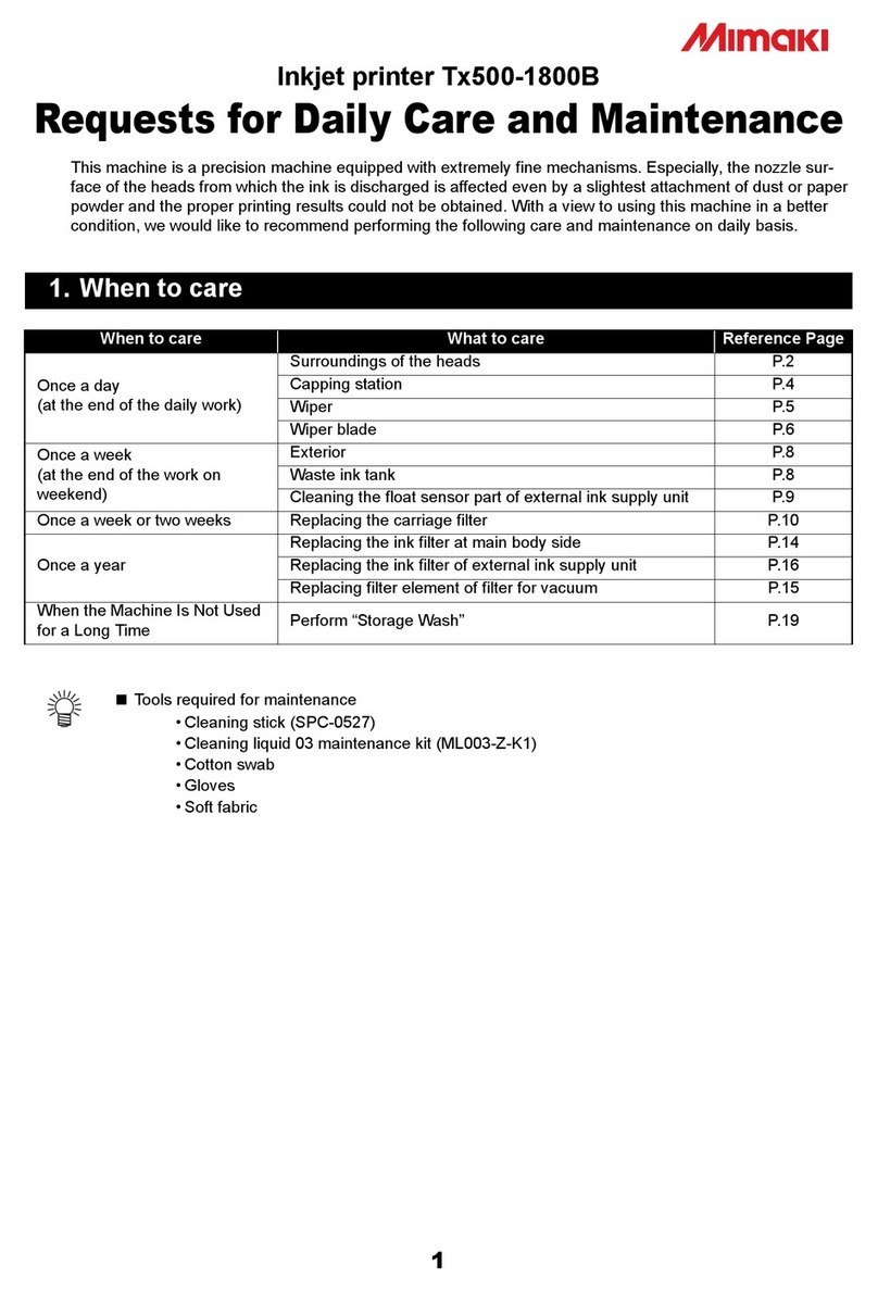
MIMAKI Tx500-1800B Maintenance manual

MIMAKI

MIMAKI Tx500-1800B Maintenance manual

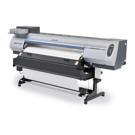
MIMAKI SUJV-160 Maintenance manual

MIMAKI

MIMAKI SUJV-160 Maintenance manual

MIMAKI CG-60AR User manual

MIMAKI

MIMAKI CG-60AR User manual

MIMAKI UJF-3042 MkII User manual

MIMAKI

MIMAKI UJF-3042 MkII User manual

MIMAKI JV5 Series Instruction Manual

MIMAKI

MIMAKI JV5 Series Instruction Manual

MIMAKI JV33-130 User manual

MIMAKI

MIMAKI JV33-130 User manual

MIMAKI JV300-130 A User manual

MIMAKI

MIMAKI JV300-130 A User manual

MIMAKI Textile Jet Tx3-1600 User manual

MIMAKI

MIMAKI Textile Jet Tx3-1600 User manual

Popular Printer manuals by other brands

Oce TDS400 user manual

Oce

Oce TDS400 user manual

Xerox Wide Format 6030 user guide

Xerox

Xerox Wide Format 6030 user guide

Star LC-8521 user manual

Star

Star LC-8521 user manual

Canon LBP-810 user guide

Canon

Canon LBP-810 user guide

Kyocera FS-9530DN specification

Kyocera

Kyocera FS-9530DN specification

Epson Stylus N10 Notices and warranty

Epson

Epson Stylus N10 Notices and warranty

Azon DTS quick start guide

Azon

Azon DTS quick start guide

Canon BJC 6000 - Color Inkjet Printer Service manual

Canon

Canon BJC 6000 - Color Inkjet Printer Service manual

Canon iP6700D - PIXMA Color Inkjet Printer Specifications

Canon

Canon iP6700D - PIXMA Color Inkjet Printer Specifications

Gainscha INTELLIGENT Series user manual

Gainscha

Gainscha INTELLIGENT Series user manual

Jolimark bp-900kll user manual

Jolimark

Jolimark bp-900kll user manual

Epson R800 - Stylus Photo Color Inkjet Printer user guide

Epson

Epson R800 - Stylus Photo Color Inkjet Printer user guide

Epson FX-2190IIN quick start guide

Epson

Epson FX-2190IIN quick start guide

Xerox DocuPrint C621 user guide

Xerox

Xerox DocuPrint C621 user guide

Brother DCP-9042CDN user guide

Brother

Brother DCP-9042CDN user guide

Microcom 428LT Operator's manual

Microcom

Microcom 428LT Operator's manual

NCR 719 II Series CLEANING

NCR

NCR 719 II Series CLEANING

Ricoh SP C250DN operating instructions

Ricoh

Ricoh SP C250DN operating instructions

manuals.online logo
manuals.online logoBrands
  • About & Mission
  • Contact us
  • Privacy Policy
  • Terms and Conditions

Copyright 2025 Manuals.Online. All Rights Reserved.