mini-box M4-ATX User manual

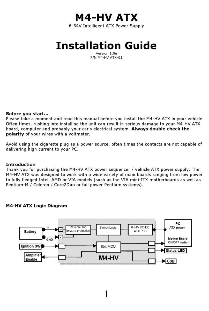
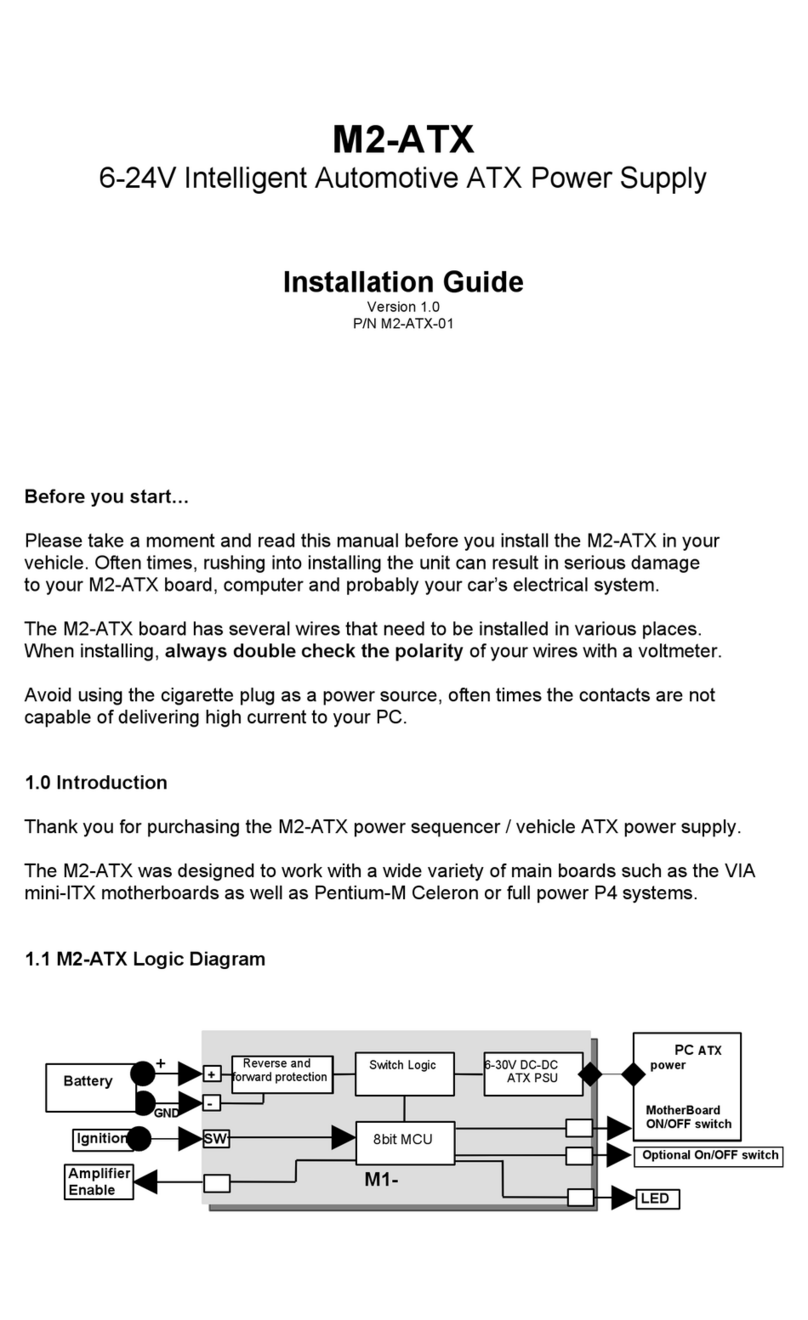
GND
+ Switch Logic 6-30V DC-DC
ATX PSU
PC ATX
power
Mother Board
ON/OFF
switch
M4-ATX
Battery
Ig itio SW
-
+
USB
8bit MCU
Amplifier
E able
Reverse nd
forw rd protection
Status LED
M4-ATX
6-30V Intelligent ATX Power Supply
I stallatio Guide
Version 1.0c
P/N M4-ATX-01
Before you start…
Ple se t ke moment nd re d this m nu l before you inst ll the M4-ATX in your
vehicle. Often times, rushing into inst lling the unit c n result in serious d m ge
to your M4-ATX bo rd, computer nd prob bly your c r’s electric l system. Always
double check the polarity of your wires with voltmeter.
Avoid using the cig rette plug s power source, often times the cont cts re not
c p ble of delivering high current to your PC.
I troductio
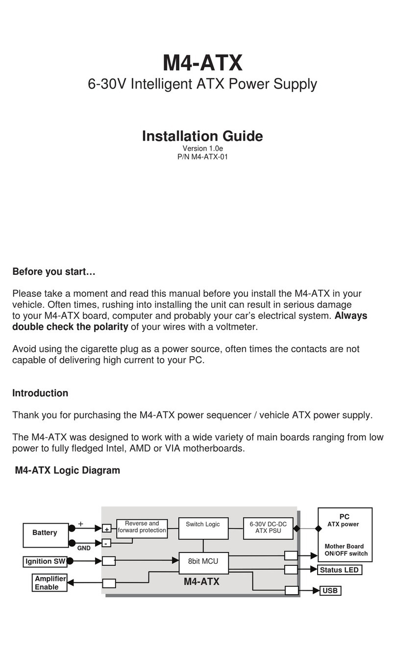
Th nk you for purch sing the M4-ATX power sequencer / vehicle ATX power supply.
The M4-ATX w s designed to work with wide v riety of m in bo rds r nging from low
power to fully fledged Intel, AMD or VIA models .
M4-ATX Logic Diagram

http://mini-box.com, Embedded PC Solutions
1.2 M4-ATX Co ectio diagram
Power I put Co ectors (bottom, right side)
Left Battery egative (GND)
Ce ter Ig itio (switched b ttery, positive. C n test by connecting it to B ttery +)
Right Battery positive (+)
(A) ATX Power Output Co ector 20/24 pi co ector
(B) 12V-ATX power output co ector 4 pi
(C) Co figuratio dip switch
(J5) For i ter al use o ly (do ot use)
(J6) Amplifier THUMP wire har ess (co ects to the M4-ATX pi header)
(J3) Fa Header
(J8) USB, Motherboard ON/OFF a d THUMP (Thump also available o J6)
1) +5V 6) To Motherbo rd ON/OFF
2) USB D- 7) To motherbo rd ON/OFF
3) USB D+ 8) Amplifier Thump
4) GND 9) GND
5) GND 19 N/C (key)
M4-ATX User Guide P ge 2

http://mini-box.com, Embedded PC Solutions
J8 show with cable har ess co ected to the
motherboard ON-OFF header (pi 7 a d 6)
IMPORTANT: Alw ys use the “Hibern te”
fe ture on your PC, never use “St ndby”.
NEVER use “h rd-off = NEVER” settings
unless you fully underst nd the risks of
b ttery depletion. Even with s fety limits
in pl ce, your c r b ttery might be not be
ble to st rt your engine.
P0: In this mode, the M4-ATX beh ves
like regul r ATX power supply.
P1 (recomme ded): Sends ON pulse to
motherbo rd when ignition is ON for more th n 2 seconds, sends OFF pulse to
motherbo rd 5 seco ds fter ignition is turned off. W its nother 1 mi ute nd then
shuts down 5VSB to conserve b ttery. In this mode, the M4-ATX consumes less th n
0.5mA. This is our recomme ded setti g.
NOTE: To reset to the M4-ATX settings to the f ctory def ults (in c se ch nges were
m de vi the USB uplink), simply power off the unit, connect jumper to JP1 nd then
power b ck up. The LED light will st rt to fl sh r pidly indic ting th t the f ctory def ults
were lo ded. Do ’t forget to Remove jumper whe do e! Disconnect M4-ATX from
b ttery for t le st 10 seconds. Next time when power is pplied, M4-ATX will oper te
from the f ctory def ults settings.
Power challe ges i a Vehicle PC: One of most difficult t sks of oper ting PC in
vehicle is power consumption while the computer is OFF. Even when your computer is
OFF, it will still consume bout 100mA on the 5V r il. When the computer is in the
suspend mode, it will consume even more power, bec use the RAM needs to be
powered t ll times. No matter how big your battery is, you will eventually drain it if
proper actions are not taken.
The M4-ATX is ddressing these issues by cutting off the 5VSB r il fter pre-defined
mount of time (see jumper ch rt, HARDOFF). During the HARDOFF if the b ttery level
drops below 11.2V for more th n one minute, M4-ATX will shut down nd re- ctiv te only
when the input volt ge is > 12V.
E gi e Cra ks, u der-voltage a d over-voltage situatio s. Another difficult t sk is
m int ining st ble power to your PC. While c r b tteries re r ted t 12V, they ctu lly
provide volt ges in between 7-11V (engine cr nks) or s high s 80 volts (lo d dump).
Most of the times, your b ttery will st y t 13.5V (while c r is running) but extr
prec utions need to t ke pl ce in order to prevent such situ tions. M4-ATX c n oper te
s low s 6V nd s high s 30V while providing strict regul tion on ll r ils long with
input volt ge cl mping nd reverse protection.
M4-ATX User Guide P ge 3
DIP Switch (ON=dow )
123POff-delay
(All rails ON)
Hard-off
(5VSB)
OFF OFF OFF P0 St nd rd PSU mode
ON OFF OFF P1 5sec 1 min
OFF ON OFF P2 5sec 1 hour
ON ON OFF P3 5sec NEVER
OFF OFF ON P4 30sec 1 hour
ON OFF ON P5 30sec NEVER
OFF ON ON P6 30min NEVER
ON ON ON P7 3hour NEVER
http://mini-box.com, Embedded PC Solutions
Loud amplifier pops whe PC starts. If your PC is connected to your c r mplifier, you
will he r loud pop when the computer is first st rted. The M4-ATX h s n ‘ nti-thump’
control th t will keep your mp OFF while the PC st rts. Simply connect the white wire
from your M4-ATX c ble h rness to your mplifier remote control pin.
Mode of operatio
1) Ignition=OFF. Nothing h ppens. M4-ATX is w iting for ignition sign ls.
2) Ignition=ON. M4-ATX w its for 2-3 seconds then turns on the 5VSB r il. After nother second M4-ATX sends
n “ON” sign l to the motherbo rd vi the 2 wires connected to the motherbo rd’s ON/OFF pins. The
motherbo rd will turn ON nd your system should st rt booting.
3) Ignition=ON. Your computer will rem in ON.
4) Ignition=OFF. M4-ATX w its for “OFFDELAY” in seconds (see jumper ch rt) nd then it turns the motherbo rd
OFF by sending sign l to the motherbo rd’s ON/OFF switch. Your computer should turn off gr cefully
(shutdown procedure). After shutdown, 5VSB will still be provided for nother “HARDOFF” seconds. In the
event where the shutdown process is longer th n “HARDOFF” (Oper ting System gets frozen, etc), power will
be shut down h rd, turning off ll power r ils. During the HARDOFF procedure, the b ttery levels will be
const ntly monitored to prevent deep disch rge situ tions.
5) M4-ATX will go to step 1, if ignition is tuned ON g in.
NOTE. When ll dip switches re off, M4-ATX cts s regul r power supply, no ignition timing, no HARDOFF. M4-
ATX will send gr tuitous “ON” pulse to the M/B when power is pplied for the first time. Do not connect the on/off
switch if you don’t w nt your PC to be st rted utom tic lly.
M4-ATX Characteristics
Minimum Input Oper ting. volt ge 6V
M ximum input Oper ting volt ge 30V (h rd cl mping will occur t 34V)
Deep-Disch rge shutdown threshold 11.2V
Input current limit (fuse protected) Mini-bl de 25A
M x Output Power 250 W tts / 300 w tts pe k
Deep Sleep Current Consumption. < 1.6mA
Stor ge nd oper ting temper ture -40 to +125 degrees Celsius (stor ge), -40 – 65C (oper ting)
MTBF 200,000 Hrs
Efficiency (Input 9-16V) >95%, ll r ils combined, 50% lo d.
Input connectors M4 screw termin l
Output Connector ATX Power 24 pin (Molex P/N 39-01-2200)
*Unit shuts down when intern l temper ture sensor indic tes > 85C. This v lue c n be ch nged with softw re.
Maximum Power Characteristics
Output R il Current (M x) Current Pe k
(<30 seconds)
Regul tion
5V 15A 20A 1.5%
3.3V 15A 20A 1.5%
5VSB 1.5A 2A 1.5%
-12V 0.15A 0.2A 10%
12V 10A (see below) 16A (see below) 2%
When oper ting t <8V or >28V or extreme temper tures, de-r te by 25%, ventil tion might be required.
When oper ting t const nt 160w tts or more forced ventil tion might be required.
12V Rail Output Curre t (12V buck/boost co verter)
Input (V) 12V out current Input (V) 12V out current
6-8V 8A (10A pe k) 11-16V 12A (16A pe k)
8-11V 10A (12A pe k) 16-30V 12A (14A pe k)
Support a d warra ty: St nd rd H rdw re W rr nty 1Ye r / US, 2 Ye r EU
M4-ATX User Guide P ge 4

http://mini-box.com, Embedded PC Solutions
Inst ll tion support: 30d ys vi web t http//www.mini-box.com
SW
SW
M4-ATX User Guide P ge 5
Table of contents
Other mini-box Power Supply manuals

mini-box
mini-box M2-ATX-01 User manual

mini-box
mini-box M1-ATX User manual

mini-box
mini-box M4-ATX-HV User manual

mini-box
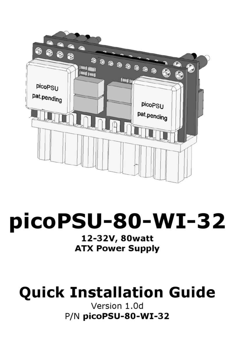
mini-box picoPSU-80-WI-32 User manual

mini-box
mini-box M3-ATX-HV User manual

mini-box
mini-box M3-ATX User manual

mini-box
mini-box M2-ATX-HV User manual

mini-box
mini-box M2-ATX User manual

mini-box
mini-box M2-ATX User manual

mini-box
mini-box M4-ATX User manual