MINICRAFT 11240 User manual

Decal Application:
Your Minicraft model includes high-quality waterslide decals. These decals adhere best to a glossy surface.
Use a sharp scissors or knife to cut individual decals from the carrier sheet. Do not cut into the clear lm
surrounding the individual decals. It is recommended that you apply one decal at a time. Place the decal
section in warm water, when rst inserted in the water your decal will curl, after approximately ten seconds
the decal will uncurl. Remove from water and lay on a paper towel. After approximately 10 - 20 seconds the
decal will slide freely from the backing paper. Use a small brush to help slide the decal from the backing
paper and into position on the model. Carefully blot excess water from the decal, using care not to move the
decal or tear it. If you choose to use a setting solution, apply a thin coat over the decal following the
manufacturer’s instruction. Allow the decal to dry overnight. Wash any adhesive residue o the model with
a small wet towel.
The Ford Model A of 1928–1931 also called the “A-bone” among rodders and customizers, was the second
huge success for the Ford Motor Company, after its predecessor, the Model T. During the 1940’s and early 50’s,
the Model “A”was a reliable, inexpensive car that proved to be ideal for customizing. With creativity and
ingenuity, the Model A’s were often customized with the addition of new engines and custom parts that
added style and performance to suit their owner’s tastes. The new Minicraft Hot Rod Roadster captures the
spirit of that era with custom wheels and tires, a at-head V-8 engine and many custom chrome parts.
Minicraft Models (USA) LLC
2136 12th Street Rockford, IL. 61104 847-429-9676
Printed in China
www.minicraftmodels.com

P Sprue 1 (Plated)
P Sprue 2 (Black)
M 4 ~ 16 (Plated)
NOTE
Some parts included will not
be used for this model
Hinge Pins Axle
Q Sprue 1 (Plated)
M 1 ~ 3 (Clear)
F 1 ~ 29 (Black)
I 1 ~ 5 (Clear)
C 1 ~ 9 (Gray)
B 1 ~ 2 (Gray) E 1 ~ 26 (Black)
L 1 ~ 16 (Gray)
G 18 ~ 21 (Black)
D 1 (Gray)
J 1 ~ 35 (Plated)
1 2 4
5
9
2
3
1
1
8
1
2
6
7
8
9
10
34
5
11
25 717716
9R
10L
22
4
7012
19 19 19 23
12
14
13
15
26 25 24 23 22
21
18 16
17
1
2
15 5 6
3 4
16
7
8
9
1413
12
11 10
2
3
4
5
67 98
20
21
22
23
24
36
37
3839
29
28
27 25
12
14
13
11
17
10
15
16
16
1
18
19
32 31 30
33
34 35
22
21
23
26
25
24
27
28
29
20 19 18
17
16
1513 12 11
2
3
414
1
10 9
42 42
72 72
72 72
4242
35 31 58
54 37
39
54
10 6
9
87
11 16
15
4
5
12 13 14
28 18 20
21
20
21
20
21
62
24
2
1
6
73
29
3
11
56 5
13 26 14
7
5
6
8
1 2 3
1
12
3 3 5
421
20
18
19
1920
Tires
Q Sprue 2 (Plated)
(Black)
59 59
30
36
36
65
31
44
45
33
55
38 38
55 71 47 43
74 75
60
63
61
51
50
52
48 53
55
38 38
55 71
1
Assemble engine block halves (1/2), oil pan (11) and transmission
housing (5). Attach intake manifold (3), distributor cap (26), distributor (29) and
water pump (28).
11
P
5
P
2
P
28
P
12
P
70
P
3
P
29
P
26
P
1
P
2
Assemble three carburetors (20/21) and air filters (19), than cement to
intake manifold. Attach throttle linkage (4) as shown. Cement fuel pump (23)
into hole on rear of intake manifold. Note diagram showing location. Cement heads (7) in place.
Attach engine mounts (12/70) as shown.
19
P
20
P
21
P
4
P
23
P
7
P
12
P
70
P
7
P
2X
Cement
Coller
Kleben
Pegar
Incollare
Colar
Kleven
DO NOTCement
Ne pas coller
Nicht Kleben
No pegar
Non collare
Nao colar
niet kleven
Optional
Choix
Auswahlmoglichkeit
Eleccion
Scelta
Opcao
Keuze
Cut away
Couper
Scheiden
Cortar
Tagliare
Cortar
Sniden
Repeat operation
Répéter l'opération
Vorgang wiederholen
Repitir la operacion
Ripetere
Repitir a operacao
Herhalen
BEFORE BEGINNING ASSEMBLY
Your MINICRAFT "Hot Rodney" model contains a wealth of highly detailed parts. Please take a moment to read
the instruction sheet to become familiar with the parts before beginning assembly.
Be sure to test the fit of all parts before gluing.
Remove the plating from the custom 'chromed' parts in the areas where glue will be applied.
Note and follow instruction icons shown below.
NOTE
Engine mounts P12 and P70
must be glued in place aligned
as shown.
(Some parts not shown for clarity).
P(19/20/21)
P(23)
23

9
P Right
25
P
14
P
22
P
56
P
10
P Left
3
5
NOTE: Underside of engine is shown. Cement starter
motor (13) to oil pan.
13
P
18
P
6
P
4
Cement coil (18) and shifter base (6) in place as shown.
25
E
12
E
15
E
1
E
18
E
2
E
6
Assemble the chassis by cementing all parts indicated to E(2), then cement
E(1) to other parts. Note diagram showing appropriate locating holes on parts E(1/2).
E(18) E(15) E(12) E(25)
Assemble generator and mount (22/14/25), then attach assembly to engine.
Cement belt and pulleys (56) to positions shown. Press fit exhausts (9/10)
(do not glue) to engine block. Exhausts should be glued in place after
fitting the engine to chassis (Step 20). Note that exhausts will later be positioned
pointing out of the sides of the engine compartment.
7
Assemble rear axle halves (61/63), trapping metal
axle between.
TOP
63
Q
61
Q
8
Cement parts (52/53) together. Pass rear axle assembly through hole
in differential/driveshaft housing (52/53), aligning the small tab with slot
on part 52.
Note tab alignment to part 52
when assembled.
53
Q
52
Q
52
Q
9
NOTE: All parts are shown upside down. Dry fit all parts to become familiar
with assembly procedure. Also refer to Step 10 below.
Attach rear suspension mount (73) to frame. Allow to dry thoroughly.
Cement differential cover (58) to rear axle assembly.
Place rear axle assembly in place, then glue shock absorbers (59) into position
on axle and suspension mount.All parts should align as shown in diagram below.
Note that forward end of driveshaft will lay in the cutouts of frame brace (E15).
Do not apply glue to this area.
IMPORTANT NOTE
It is recommended to use a slow-setting glue such as tube cement
or epoxy for assembling the shock absorbers (59) to the
driveshaft/axle assembly and part 73, as these parts should be assembled
simultaneously for proper alignment.
Assembly viewed from rear. Note alignment of parts.
Assembly viewed from side. Note alignment of parts.
10
NOTE: All parts are shown upside down. If not installed
in Step 9, cement rear spring (60) to holes in axle, and to
suspension mount (Part 73).
Cement stabilizers (50/51) to rear axle and driveshaft housing.
59
Q
59
Q
58
Q
73
P
50
Q
51
Q
60
Q
45

12
Trap thicker tire between outer rim (42) and inner rim (72), then glue brake drum (55) to
inner rim. Pass metal rear axle through this assembly, then glue to hub (39).
Pass other end of metal axle through rear axle assembly. Cement Q(54) to Q(61/63).
11
Trap thicker tire between outer rim (42) and inner rim (72), then glue brake drum (55) to
inner rim. Pass metal rear axle through this assembly, then glue to hub (39).
Pass other end of metal axle through rear axle assembly. Cement Q(54) to Q(61/63).
39
Q
42
Q
3
R
72
Q
55
Q
54
Q
39
Q
42
Q
4
R
72
Q
55
Q
54
Q
13
Trap thinner tire between outer rim (42) and inner rim (40), then glue brake drum (38) to
inner rim. Pass stub axle of part 37 through this assembly, then glue to hub (39).
Cement support arms (34/31) to part 37. Attach steering arm (44) to part 37.
39
Q
42
Q
40
Q
38
Q
37
Q
34
Q
44
Q
31
Q
1
R
14
Trap thinner tire between outer rim (42) and inner rim (40), then glue brake drum (38) to
inner rim. Pass stub axle of part 31 through this assembly, then glue to hub (39).
Cement support arms (34/30) to part 37.
38
Q
40
Q
2
R
42
Q
39
Q
37
Q
34
Q
30
Q
16
15
Pass stub on end of steering linkage (43) through hole in steering arm,
then glue cap (71) on end. Pass other stub end through link (45),
and glue cap (71) on end. Leave assembly loose until Step 23.
43
Q
45
Q
36
Q
75
Q
35
Q
74
Q
36
Q
71
Q
71
Q
NOTE: All parts shown upside down. Steering linkage is not shown for clarity.
Cement forward spring (35) to frame crossbar. Glue shock mounts (74/75) to frame,
aligning with crossbrace as shown. Glue shock absorbers (36) in place as shown.
Snap wheel assembly onto stubs.
31
Q
34
Q
37
Q
Note alignment (viewed from front).
35
Q
18
E
74
Q
75
Q
36
Q
36
Q
Note Alignment (viewed from front).
Parts shown upside down.
67

17
NOTE: All parts shown upside down.
Snap wheel assembly onto stubs.
18
NOTE: All parts shown upside down. Front suspension parts not shown
for clarity. Pass end stubs of tie rod (33) through holes in steering arms
and glue caps (71) on ends.
71
Q
33
Q
71
Q
Be sure to test the fit
of parts Q(33/35) in the
respective holes in mating parts.
Non-glued parts should move
easily for proper movement
of operable features.
PLEASE NOTE
Press fit
21
Turn model over.
Glue together steering box parts (47/48). Carefully slide the shaft between
the exhaust pipes, and glue steering box to frame. Press fit the steering link
onto the shaft of part 47.
47
Q
48
Q
19
Cement floorboard D(1) to B (1). Cement fender B(3) in place.
NOTE
Some parts not shown
for clarity.
20
Cement battery parts F(22/26) together and glue to frame in position shown.
Cement fenders and floorboard assembly to frame. Cement engine
assembly in position, connecting to driveshaft. Glue exhausts into position.
1
D
2
B
1
B
19
G
18
G
NOTE
Some parts not shown
for clarity.
Parts are shown upside down.
26
F
22
F
22
NOTE: All parts are shown upside down.
Glue brace (65) in place, attaching to stubs on forward
crossbeam and also to the stub on the oil pan.
65
Q
23
Assemble seat back L (1) to seat L (4), aligning tabs
with slots in floorboard.
4
L
1
L
24
Attach parts (26/27) as shown. Note shift knob J (26) inserts into
hole on top of transmission housing.
27
J
26
J
25
Cement all controls in place as shown.
4
E
8
C
12
J
3
J
4
J
6
E
7
E
1
C
Running lights on part J(20) may be
removed to match box illustration.
26
Cement oil filter (16/17) together, then to
to dash C (1). Attach trim J (20) to dash.
17
P
16
P
20
J
2
I
2
I
1
C
89

27
Cement dash to chassis, carefully threading the steering
linkage through hole in firewall and aligning it with the small
indentation on the lower dash. Cement part E(4) to dash,
wrapping around steering linkage. Cement steering wheel parts
as shown and cement to steering linkage.
27
J
14
J
13
J
28
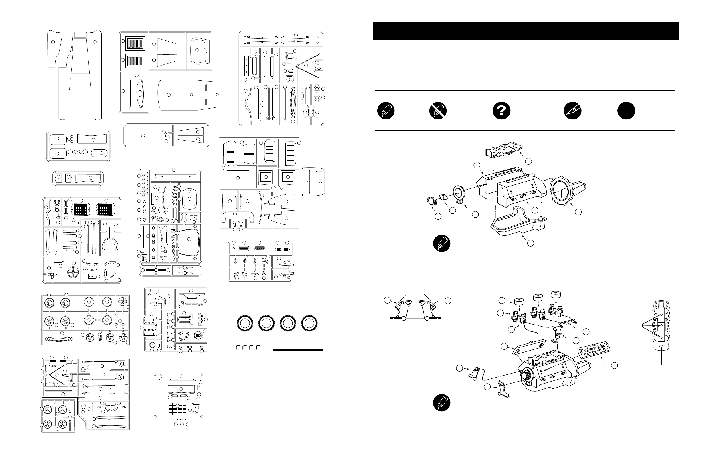
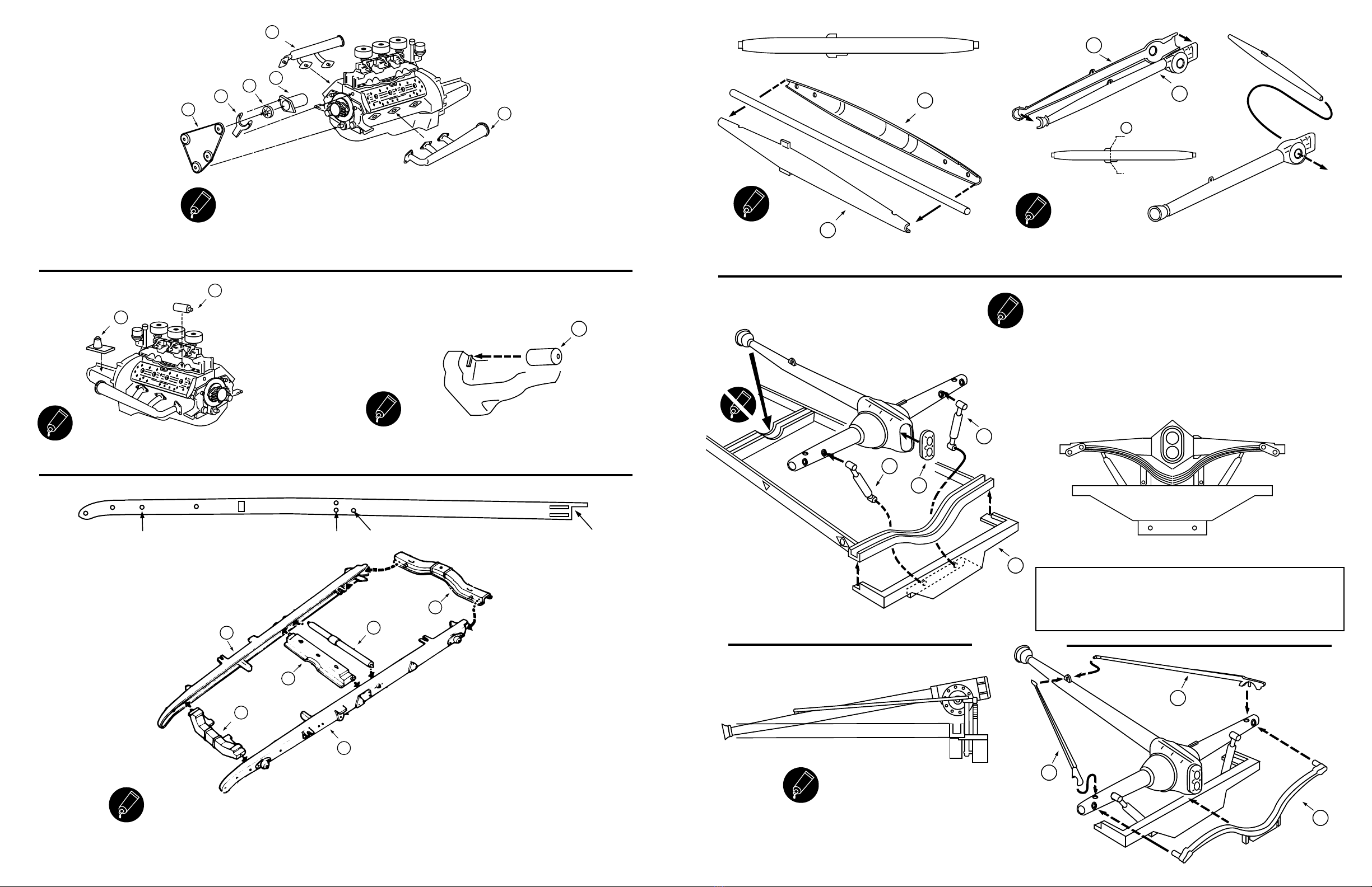
Assemble radiator a shown. Cement water hoses (62/24) to the engine. Glue
radiator in place on frame, the glue hoses to radiator. Cement tie rods (13/14)
in place as shown.
Fit parts into holes
as indicated
14
B
24
B
13
B
13
F
14
F
24
B
62
B
62
B
1
F
2
F
2
J
24
F
25
F
29
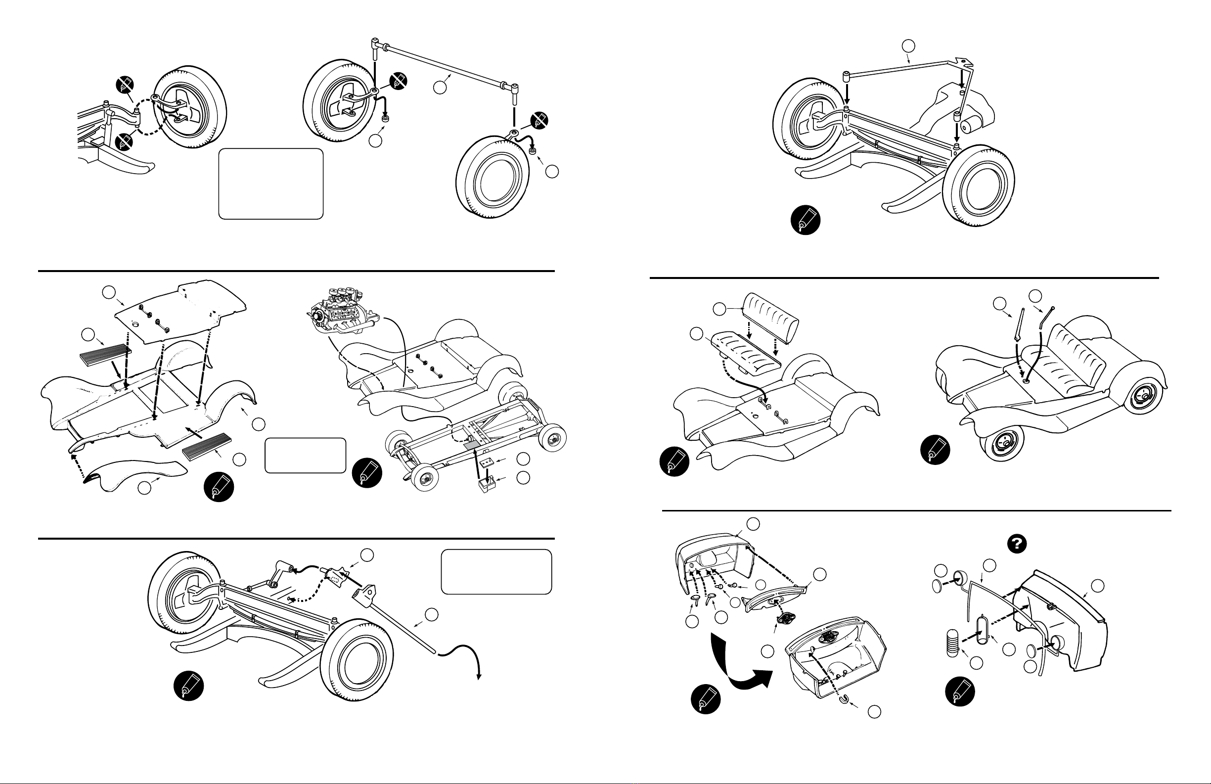
Assemble seat L (15) and L (2), then insert into body
shell L (16). Do not glue.
15
L
16
L
2
L
30
Cement sides L (7) and L (8) to body shell. Do not apply glue
to hinge points. Attach seat bottom L (3).
7
L
3
L
8
L
OPTIONAL STEP OPTIONAL STEP
4
E
31
Cement body shell to assembled chassis.
32
Cement door halves L (10,14) together. Cement hinge pin
to hinge E (9), then cement hinges E (8,9) to door.
33
Cement door halves L (9,13) together. Cement hinge pin
to hinge E (9), then cement hinges E (8,9) to door.
35
34
Fit (do not cement) hinges F5 to door hinges. Hold door
shut and in place with tape, then carefully cement hinges
F (5) to body.
Fit (do not cement) hinges F5 to door hinges. Hold door
shut and in place with tape, then carefully cement hinges
F (5) to body.
8
E
9
E
13
L
9
L
5
F
5
F
5
F
5
F
36
Glue part C(2) and C(3) together using a slow-setting cement.
Align assembly with radiator and firewall and glue in place.
3
C
2
C
9
E
8
E
14
L
10
L
Shorten one end of hinge pins to dimensions shown.
Glue into position as shown.
(Part is shown upside down).
End view
1/16"
(2mm)
2X
Steps
32/33
10 11

37
Cement windshield M (3) to frame L (15), then to frame L (14). Slide L (10, 11)
onto ends of L (14), then glue to body. Attach side screens M (2) and accessories.
15
L
5
M
3
M
14
L
10
L
11
L
24
M
23
M
38
Assemble lights and glue to fenders. Cement
handles J (29) to body, left and right sides.
Cement hubcaps J(30) to wheel hubs.
39
Cement two taillights J(25) to body.
Attach handles M(12,13,14).
14
M
13
M
29
J
30
J
10
J
3
I
3
I
12
M
25
J
25
J
(Left and Right wheels)
30
J
(Left and Right wheels)
Table of contents
Other MINICRAFT Motorized Toy Car manuals