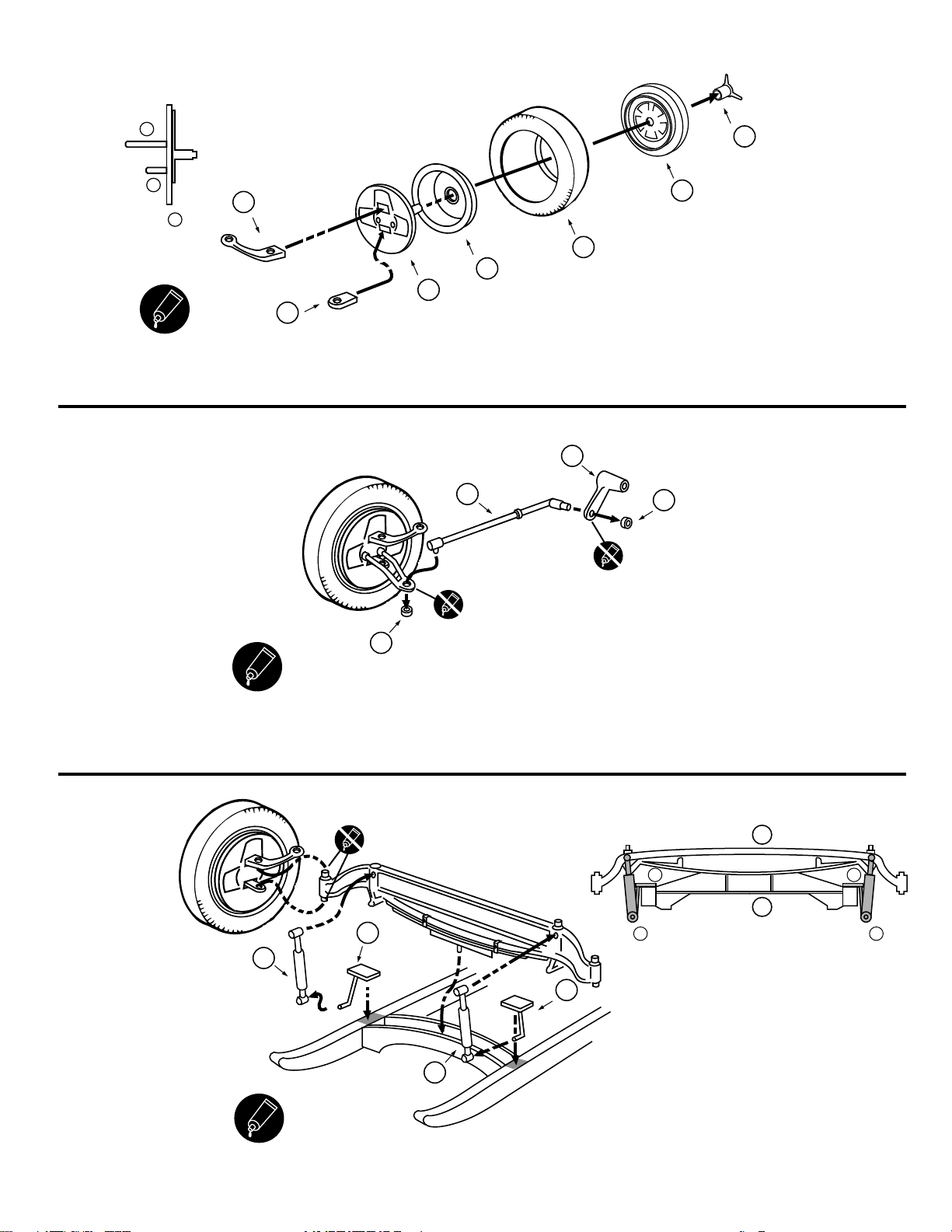
7
Assemble rear axle halves (61/63), trapping metal
axle between.
TOP
63
Q
61
Q
8
Cement parts (52/53) together. Pass rear axle assembly through hole
in differential/driveshaft housing (52/53), aligning the small tab with slot
on part 52.
Note tab alignment to part 52
when assembled.
53
Q
52
Q
52
Q
9
NOTE: All parts are shown upside down. Dry fit all parts to become familiar
with assembly procedure. Also refer to Step 10 below.
Attach rear suspension mount (73) to frame. Allow to dry thoroughly.
Cement differential cover (58) to rear axle assembly.
Place rear axle assembly in place, then glue shock absorbers (59) into position
on axle and suspension mount.All parts should align as shown in diagram below.
Note that forward end of driveshaft will lay in the cutouts of frame brace (E15).
Do not apply glue to this area.
IMPORTANT NOTE
It is recommended to use a slow-setting glue such as tube cement
or epoxy for assembling the shock absorbers (59) to the
driveshaft/axle assembly and part 73, as these parts should be assembled
simultaneously for proper alignment.
Assembly viewed from rear. Note alignment of parts.
Assembly viewed from side. Note alignment of parts.
10
NOTE: All parts are shown upside down. Cement rear spring (60)
to holes in axle, and to suspension mount (Part 73).
Cement stabilizers (50/51) to rear axle and driveshaft housing.
59
Q
59
Q
58
Q
73
P
50
Q
51
Q
60
Q