Minuteman Rack/Tower Extended Runtime Battery Packs User manual

User's Manual
Rack/Tower Extended
Runtime Battery Packs
Para Systems, Inc.
1455 Lemay Dr.
Carrollton, TX 75007
Phone: 1-972-446-7363
Fax: 1-972-446-9011
Internet: minutemanups.com
UPS Sizing: sizemyups.com
P/N 34000424 R3

1
1. Introduction 2
2. Rear Panel 6
3. Installation 7
4. Replacing the Battery 12
5. Obtaining Service 16
6. Specifications 17
7. Limited Product Warranty 18
TABLE OF CONTENTS

3
2
CAUTION! To de-energize the Battery Pack:
1. If the UPS is on press and release the Off/On button.
2. Disconnect theUPSfromthewalloutlet.
3. Turn off the DC breaker on the rear panel of the Battery Pack.
4. Disconnect the battery cable from the rear panel of the UPS.
5. To de-energize the Battery Pack completely, disconnect the batteries.
RECIEVING INSPECTION
Once you receive the product it should be visually inspected for damage that
may have occurred in shipping. Immediately notify the carrier and place of
purchase if any damage is found. Warranty claims for damage caused by the
carrier will not be honored by the manufacturer. The packing materials that
the product was shipped in were carefully designed to minimize any shipping
damage. In the unlikely case that the product needs to be returned to the
manufacturer, use the original packing material. Since the manufacturer is
not responsible for shipping damage incurred when the product is returned,
the original packing material is inexpensive insurance. PLEASE SAVE THE
PACKING MATERIALS!
Chapter 1: Introduction
IMPORTANT SAFETY INSTRUCTIONS
SAVE THESE INSTRUCTIONS !
Thank you for purchasing this power protection product. It has been de-
signedandmanufacturedto providemany yearsof troublefree service. Please
read this manual before installing your BPRTXL Battery Pack, models
BP24RTEXL, BP48RTEXL, BP36RTEXL, BP72RTEXL as it provides impor-
tantinformation that should befollowed during the installation andthe mainte-
nance of the Battery Packs and batteries allowing you to correctly set up your
system for the maximum safety and performance. Included is information on
customer support and factory service, if it is required. If you experience a
problem with the Battery Packs please refer to Obtaining Service section in
this manual to collect enough information so that the Technical Support De-
partment can rapidly assist you.
CAUTION! This Battery Pack series is ONLYintended to be installed in an
indoor temperature controlled environment that is free of conductive contami-
nants. This Battery Pack series is not for use in a computer room as defined
in the Standard for the Protection of Electronic Computer/Data Processing
EquipmentANSI/NFPA75. Selecta location which will providegoodair circu-
lation for the Battery Pack and UPS at all times.
CAUTION! Themaximum ambientoperating temperaturefor thisBattery Pack
series is 40°C (“0 ~ 40°C” for Ambient Operation).
Theexternal ventsandopenings onthe Battery Packare provided forven-
tilation. To ensure reliable operation of the UPS and to protect the UPS
from overheating, these vents and openings must not be blocked or cov-
ered. Do not insert any object into any of the vents or openings that may
hinderthe ventilation.
Install the Battery Pack in a well ventilated area, away from excess mois-
ture,heat, dust, flammable gasor explosives.
Leave adequate space (at least 15cm) around all sides of the Battery
Pack for proper ventilation.
Do not mount the Battery Pack with its front or rear panel facing down at
any angle.
Before usage, you must allow the Battery Pack to adjust to room temper-
ature (20°C~25°C or 68°F~77°F) for at least one hour to avoid moisture
condensing inside the UPS.
WARNING: Risk of Electrical Shock. Hazardous live parts inside these Bat-
tery Packs are energized from the battery.
WARNING: These Battery Packs contains potentially hazardous voltages.
Do not attempt to disassemble the Battery Pack beyond the battery replace-
ment procedure. These Battery Packs contain no user serviceable parts.
Repairs and Battery replacement must be performed by QUALIFIED SER-
VICE PERSONNEL ONLY.
CAUTION! DO NOT USE THE MOUNTING BRACKETS TO LIFT THE BAT-
TERYPACK. Themounting brackets areONLYforsecuring theBatteryPack
to the rack.
WARNING: Qualified Service Personnel ONLY must perform the Installa-
tionand Servicing of these BatteryPacks. MINUTEMANaccepts no liabilities
and is not limited to: injury to the Service Personnel, or damages to; the Bat-
tery Pack, the UPS, or the connected equipment caused by the incorrect
installation or servicing of the Battery Packs.

5
4
NOTICE: Thisequipment has beentestedand found tocomply with the limits
for a ClassA computing device in accordance with the specifications in Sub-
part J of Part 15 of FCC Rules and the ClassAlimits for radio noise emissions
from digital apparatus set out in the Radio Interference of the Canadian De-
partment of Communications. These limits are designed to provide reason-
able protection against such interference in a residential installation. This
equipment generates and uses radio frequency and if not installed and used
properly, that is, in strict accordance with the manufacturer's instructions, this
equipment may cause interference to radio and television reception. If this
equipmentdoes cause interference to radioor television reception, which can
be determined by turning the equipment off and on, the user is encouraged to
try to correct the interference by one or more of the following measures:
Re-orientthe receivingantenna.
Relocatethe computer with respect tothe receiver.
Movethe computeraway from thereceiver.
Plugthe computer into a differentoutlet so that thecomputerand receiver
areon different branch circuits.
Shieldedcommunications interface cablesmust be usedwith this product.
WARNING: Changes or modifications to this unit not expressly approved
by the party responsible for compliance could void the user's authority to
operatethe equipment.
Life Support Policy
Asa general policy,wedo not recommendthe use of anyof our productsin life
supportapplications wherefailureor malfunctionof the productcan be reason-
ablyexpected to causefailure of thelifesupport device orto significantly affect
its safety or effectiveness. We do not recommend the use of any of our prod-
ucts in direct patient care. We will not knowingly sell our products for use in
such applications unless it receives in writing assurances satisfactory to us
that (a) the risks of injury or damage have been minimized, (b) the customer
assumes all such risks, and (c) our liability is adequately protected under the
circumstances.
Examplesof devicesconsidered tobe lifesupportdevices areneonatal oxygen
analyzers,nerve stimulators (whetherused for anesthesia, painrelief, or other
purposes), auto transfusion devices, blood pumps, defibrillators, arrhythmia
detectorsand alarms, pacemakers, hemodialysissystems, peritoneal dialysis
systems,neonatal ventilator incubators,ventilators for both adultsand infants,
anesthesiaventilators, and infusionpumps as wellas any otherdevices desig-
nated as “critical” by the United States FDA.
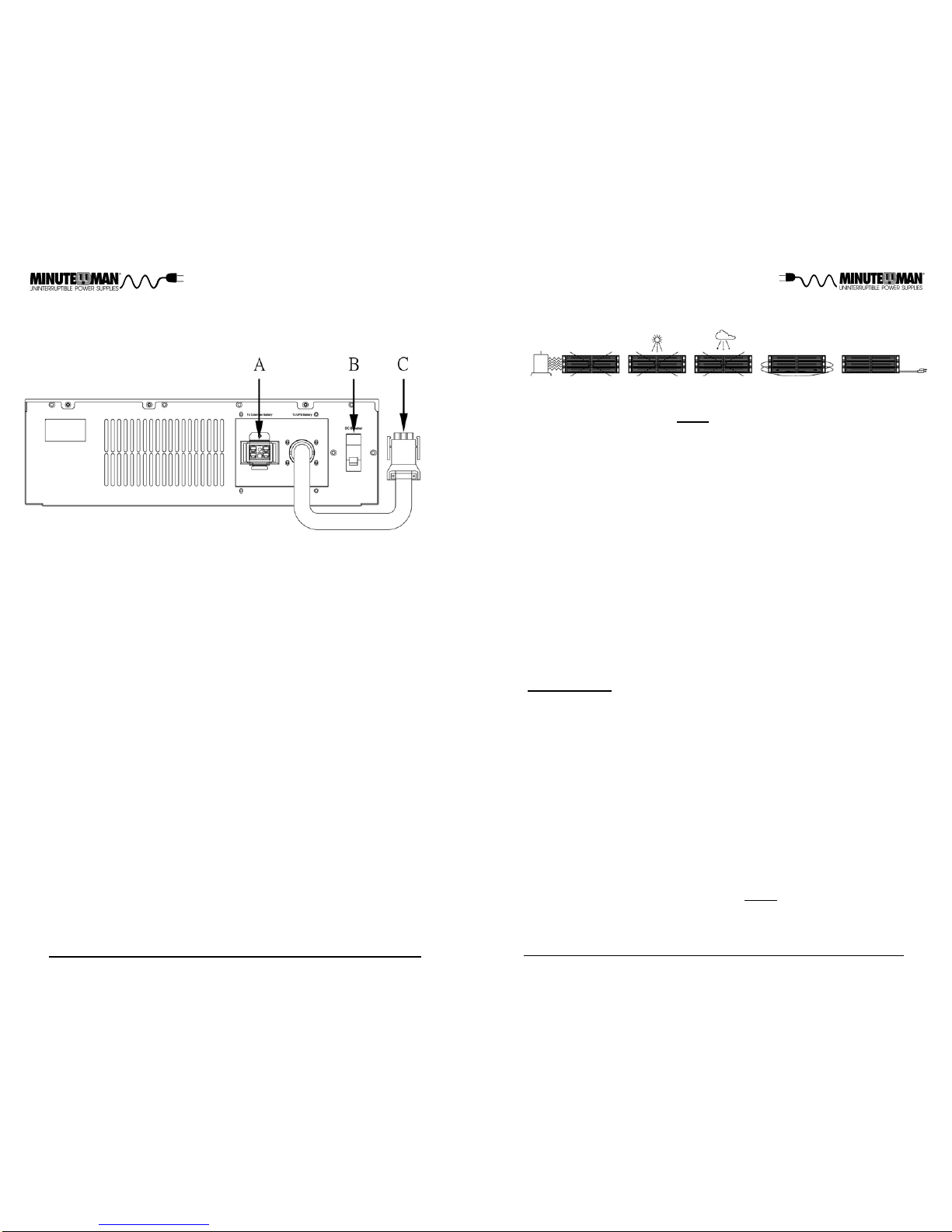
WARNING: Qualified Service Personnel ONLY mustperform the Installa-
tionand Servicing of these BatteryPacks. MINUTEMANaccepts no liabilities
and is not limited to: injury to the Service Personnel, or damages to; the
Battery Pack, the UPS, or the connected equipment caused by the incorrect
installation or servicing of the Battery Packs. These Battery Packs MUST be
operatedwith their respective UPSmodels,see the table below:
BP24RTEXL
UPS
Model ED1000RM2U
ED1000RMT2U
BP72RTEXL
Model
E2000RTXL2U
E3000RTXL2U
E3000RTXLT2U
ED3000RM2U
ED3000RMT2U
BP48RTEXL
ED1500RM2U
ED2000RM2U
ED1500RMT2U
ED2000RMT2U
BP36RTEXL
E750RTXL2U
E1000RTXL2U
E1500RTXL2U
E1500RTXLT2U
© COPYRIGHT 2014 BY PARASYSTEMS, INC.
AllRights Reserved.All rightsof thisUser Manual (“Manual”),including but not
limited to the content, information, and figures are solely owned and reserved
by Para Systems, Inc. (“Para Systems”). The Manual can only be applied to
the operation or the use of this product.Any disposition, duplication, dissemi-
nation, reproduction, modification, translation, extraction, or usage of this
Manual in whole or in part is prohibited without the prior written permission of
ParaSystems. Giventhat ParaSystems will continuouslyimprove anddevelop
the product, changes may be made to the information in this Manual at any
time without obligation to notify any person of such revision or changes. Para
Systems will make all possible efforts to secure the accuracy and the integrity
of this Manual. Para Systems disclaims any kinds or forms of warranty, guar-
antee,or undertaking, either expresslyor implicitly,including but notlimitedto
thecompleteness, faultlessness, accuracy,non-infringement,merchantability
or fitness for a particular purpose of the Manual.

7
6
A. The External Battery connector is for Daisy Chaining additional Battery Packs.
B. The DC Circuit Breaker connects and disconnects the DC bus voltage from the
BatteryPackto the UPS. The DC Circuit Breaker will trip in the event of a DC over-
current condition.
C. The External Battery cable is for connecting the Battery Pack to the UPS or Daisy
Chaining additional Battery Packs.
Chapter 2: Rear Panel Chapter 3: Installation
This Battery Pack series is ONLYintended to be installed in an indoor tem-
perature controlled environment that is free of conductive contaminants. DO
NOToperate the Battery Packin: extremely dusty and/or uncleanareas, loca-
tions near heating devices, water or excessive humidity, or where the Battery
Pack is exposed to direct sunlight. Select a location, which will provide good
air circulation for the Battery Pack at all times.
Route cables so they cannot
be walked on or damaged. This Battery Pack series is not for use in a com-
puter room as defined in the Standard for the Protection of Electronic Com-
puter/DataProcessing EquipmentANSI/NFPA75. Typical battery lifeis3 to 5
years. Environmental factors do affect battery life. High temperatures, poor
ventilationsand frequent, shortduration discharges havea negative impacton
battery life.
INSTALLATION
Besure to read theinstallation placement and allthe cautions before installing
the Battery Pack. Place the Battery Pack in the final desired location and
completethe rest of the installation procedure.
WARNING! These Battery Packs are extremely heavy. Any time the Battery
Pack has to be handled be sure to use, enough personnel, strong supports
and equipment to safely handle the Battery Pack.
CAUTION! DO NOT USE THE MOUNTING BRACKETS TO LIFT THE BAT-
TERYPACK. Themounting bracketsare ONLYfor securing the Battery Pack
to the rack.
NOTE: Whenusing these Battery Packs, theUPS must be configured sothat
theUPSwill report the correct estimated runtime on theLED/LCDscreen and
in the Power Monitoring software and/or the SNMP card. See the Power
Monitoring software or the SNMP card’s User's Manual to configure the UPS.
Operating Temperature (Max): 0 to 40 degrees C (+32 to +104 degrees F)
Operating Elevation: 0 to 3,000m (0 to +10,000 ft)
Operatingand Storage RelativeHumidity: 95%, non-condensing
Storage Temperature: -15 to +45 degrees C (+5 to +113 degrees F)
Storage Elevation: 0 to 15,000m (0 to +50,000 ft)

9
8
TOWERCONFIGURATION
The tower configuration allows the user to install the Battery Pack in the up-
right position next to the UPS. The tower brackets are provided with the Bat-
tery Pack. WARNING: Use two or more people when installing the Battery
Pack. Use CAUTION, the Battery Pack is extremely heavy.
1. Oncethe location of the BatteryPack has been determined, lay theBattery
Pack on its side. (FIG. 1)
2. Attached the tower brackets to the Battery Pack with the retaining screws.
(FIG. 1)
3. Rotate the Battery Pack to the up-right position. Ensure the Battery Pack
is stable. (FIG. 2)
4. The Tower Configuration is complete. See Connecting the Battery Pack.
RACKMOUNTCONFIGURATION
TheBattery Pack comes withmounting brackets and rails forthe standard 19"
(46.5cm) 4-post rack. The screws for mounting the Battery Pack to the rack
are not included (screw size varies with rack size).
1. Mount the rails to the 4-post rack. (FIG. 1)
2. Locate the mounting bracket screw holes on the side panels of the Battery
Pack, at the front of the Battery Pack. (FIG. 2)
3. Align the mounting bracket with the mounting bracket screw holes. (FIG. 2)
4. Attach the mounting bracket with the retaining screws. (FIG. 2)
5. Install the Battery Pack onto the Rails and secure the Battery Pack to the
rackwith theretainingscrews.(FIG. 3) WARNING: Usetwo ormore people
when installing the Battery Pack. Use CAUTION, the Battery Pack is ex-
tremely heavy. Do not move the rack after the units have been installed.
The rack maybe unstable due to the weight distribution.
6. The Rackmount Configuration is complete. See Connecting the Battery
Pack.
FIG. 1
FIG. 2
FIG. 3
FIG. 1 FIG. 2

11
10
DAISYCHAINING
(QUALIFIEDSERVICEPERSONNELONLY)
"DaisyChaining"means hooking one Battery Pack to another Battery Pack to
another Battery Pack, this chain could go on indefinitely. Follow the steps
below to Daisy Chain the Battery Packs.
1. Besure to readthe installation placementprocedure,all of thecautions and
the safety precautions before Daisy Chaining the Battery Pack(s).
2. Make sure that the DC circuit breakers on the rear panel of the Battery
Packs are in the Off position. CAUTION: If the Battery Pack's DC circuit
breaker is in the On position, the battery voltage will be present at the open
end of the Battery Pack's external battery cable and external battery con-
nector.
3. Turn the UPS off and disconnect the UPS's input power cord from theAC
wall outlet.
4. RemovetheExternal BatteryConnector coverfrom theUPS's rearpaneland
the additional Battery Packs.
5. Verify, before plugging the external battery cable into the UPS's external
battery connector or the Battery Pack's external connector that they mate
red to red and black to black.
6. Connect the external battery cable from the first Battery Pack to the exter-
nal battery connector on the UPS.
7. Connectthe external battery cable from thesecond Battery Pack to the ex-
ternal battery connector on the first Battery Pack.
8. TurnALL of the DC circuit breakers on the rear panel of the Battery Packs
to the On position.
9. The Battery Packs are ready for normal operation, see the UPS User's
Manual for the normal startup of the UPS.
NOTE: Thereisno maximumnumber forDaisyChaining theDC busvoltagefor
the Battery Packs.
CONNECTINGTHEBATTERYPACK
(QUALIFIEDSERVICEPERSONNELONLY)
NOTE: When using these Battery Packs, the UPS must be configured
so that the UPS will report the correct estimated runtime on the LED/
LCD screen and in the Power Monitoring software and/or the SNMP
card. See the Power Monitoring software or the SNMP card’s User's
Manual to configure the UPS.
Number of External Battery Packs to enter in
thepowermonitoringsoftware or the SNMP card
BP24RTEXL 5
Model
BP36RTEXL 3
BP48RTEXL 3
BP72RTEXL 3
1. Besure to readthe installation placementprocedure,all of thecautions and
the safety precautions before connecting the Battery Pack(s).
2. Make sure that the DC circuit breaker on the rear panel of the Battery Pack
is in the Off position. CAUTION: If the Battery Pack's DC circuit breaker
is in the On position, the battery voltage will be present at the open end of
the Battery Pack's external battery cable and external battery connector.
3. Turn the UPS off and disconnect the UPS's input power cord from theAC
wall outlet.
4. Removethe External Battery Connectorcoverfrom the UPS's rearpanel.
5. Verify, before connecting the Battery Pack's external battery cable into the
UPS's external battery connector, that they mate red to red and black to
black. NOTE: The red connector is the battery positive (+) and the black
connector is the battery negative (-). Connect the external battery cable
from the BatteryPack to theexternalbattery connector onthe UPS. NOTE:
If connecting more than one Battery Pack see Daisy Chaining.
6. Turn the DC circuit breaker on the rear panel of the Battery Pack to the On
position.
7. The Battery Packs are ready for normal operation, see the UPS User's
Manual for the normal startup of the UPS.

13
12
BATTERYREPLACEMENT PROCEDURE
(QUALIFIEDSERVICEPERSONNELONLY)
PLEASE READ THE CAUTIONSAND WARNINGS BEFOREATTEMPTING
TOREPLACETHE BATTERIES
Hot-swappable batteries mean that the batteries can be replaced without
poweringdown the whole UPS system.
NOTE: Ifthereisapower interruptionwhile replacingthe hot-swappablebatter-
ies, with the UPS on, the load will not be backed up. To hot-swap the Battery
Pack's batteries start with step number 6.
1. Turn off the equipment that is plugged into the output receptacles of the
UPS.
2. Press and release the Off button on the front panel to turn the UPS off.
3. Unplug the UPS'sAC power cord from the AC wall outlet.
4. Unplug the equipment from the output receptacles of the UPS.
5. Unplug the computer interface cable from the rear panel of the UPS.
6. Turn off all of the DC circuit breakers on the rear panel of all of the Battery
Packs.
7. Disconnect all of the external battery cables.
8. Removethe front panel retainingscrew cover plates. (FIG. 1)
9. Remove the front panel retaining screws. (FIG. 2)
10. Removethe front panel.
11. Remove the retaining screws for the battery retaining bracket. (FIG. 3)
12. Removethe battery retaining bracket.(FIG. 3)
13. Cut and remove all of the battery cable ties from the battery modules.
14. Disconnect the battery connectors (red and black) one from each battery
module. (FIG. 4)
15. One at a time grasp the battery pull tabs and gently pull the battery mod-
ules out of the Battery Pack and set on the floor. (FIG. 4)
NOTE: UseCaution, the battery modulesare heavy.
16. Removethe tape that goes around the batterymodule.
17. Remove the top half of the plastic battery tray.
18. Disconnect the battery positive (red) wires.
19. Disconnect the battery negative (black) wires.
20. Disconnect the battery jumper wires.
BP24RTEXL
BP48RTEXL
BatteryQty/Rating 20 - 12V9.0Ah
BP36RTEXL
BP72RTEXL
Model#
CAUTION: Replacethe batteries withthe same numberandtype as originally
installed in the Battery Pack. These batteries have pressure operated vents.
TheseBattery Packs contain sealed non-spillable maintenancefree lead acid
batteries.
Yuasa Part # REW45-12
CSB Part # HR1234W F2
18- 12V9.0Ah
WARNING! This Battery Pack contains potentially hazardous voltages. Do
not attempt to disassemble the Battery Pack beyond the battery replacement
procedure. These Battery Packs contain no user serviceable parts. Repairs
and Battery replacement must be performed by QUALIFIED SERVICE PER-
SONNELONLY.
CAUTION: Donot open or mutilatebatteries. Releasedelectrolyte is harmful
to the skin and eyes and may be toxic.
(QUALIFIEDSERVICEPERSONNELONLY)
CAUTION: Do not dispose of batteries in a fire. The batteries may explode.
The batteries in this Battery Pack are recyclable. Dispose of the batteries
properly. The batteries contain lead and pose a hazard to the environment
and human health if not disposed of properly. Refer to local codes for proper
disposal requirements or return the battery to the supplier.
CAUTION: Althoughbattery systemvoltagesare only24VDC, 36VDC,48VDC
and 72VDC the battery system can still present a risk of electrical shock.
These batteries produce sufficient current to burn wire or tools very rapidly,
producing molten metal. Observe these precautions when replacing the bat-
teries:
1.Remove watches, rings, or other metalobjects.
2.Use hand tools withinsulated handles.
3. Wear protective eye gear (goggles), rubber gloves and boots.
4. Do not lay tools or other metal parts on top of batteries.
5. Disconnect the charging source prior to connecting or disconnecting the
battery terminals.
6. Determine if the battery is inadvertently grounded. If the battery is, remove
the source of the grounding. Contact with any part of a grounded battery
can result in an electrical shock. The likelihood of such shock will be reduc-
ed, if such grounds are removed during installation and maintenance.
TheseBattery Packshave an easyto replacehot-swappable batteries. Please
read all of the WARNINGS and CAUTIONS before attempting to service the
batteries.
NOTE: Ifthereisapower interruptionwhile replacingthe hot-swappablebatter-
ies, with the UPS on, the load will not be backed up.
Chapter 4: Replacing The Battery

15
14
FIG. 2
FIG. 3
FIG. 4
21. Remove the old batteries from the bottom half of the plastic battery tray.
22. Installthe new batteriesinto the bottomhalf of theplastic battery trayin the
same position as the original batteries.
23. Verify proper polarity. Re-install the battery jumper wires on the new
batteries.
24. Verifyproper polarity. Reconnectthe battery negative(black)wires.
25. Verifyproper polarity. Reconnectthe battery positive(red) wires.
26. Install top half of the plastic battery tray onto the batteries.
27. Tape the battery module together.
28. Slide the battery modules into the Battery Pack.
29. Secure the battery cables with the battery cable ties.
30. Verify proper polarity. Reconnect the battery connectors (red and black).
NOTE: Some sparking might occur, this is normal.
31. Re-install the battery retaining bracket. (FIG. 5)
32. Re-install the retaining screws for the battery retaining bracket. (FIG. 5)
33. Re-install the front panel on the Battery Pack.
34. Re-install the front panel retaining screws. (FIG. 6)
35. Re-installthe front panel retainingscrew cover plates. (FIG. 7)
36. Reconnect all of the external battery cables.
37. Turnonall of the DC circuit breakers on the rearpanelof all of the Battery
Packs.
38. Properly dispose of the old batteries at an appropriate recycling facility or
return them to the supplier in the packing material for the new batteries.
39. The Battery Pack is ready for normal operation.
NOTE: Ifthe UPS hasa Weak/BadBatteryAlarmafterreplacing the batteries,
the user must initiate a self test to clear the Weak/Bad Battery Alarm. To
initiate a self test see section 4 "SELF TEST" in the UPS's User's Manual.
FIG. 1
FIG. 5
FIG. 6
FIG. 7

17
16
Battery Type
24VDC
Typical Recharge Time
BP24RTEXL
ModelNumber
SYSTEMSPECIFICATIONS
Format Rack/Tower Convertible
BATTERYSYSTEM
Typical Battery Life
System Current 40 Amps
20 - 12V9.0Ah
Battery Qty/Rating
BP72RTEXL
System Voltage
Sealed,Non-Spillable,MaintenanceFree,ValueRegulated,LeadAcid
3-5 years, depending on discharge cycles and ambient temperature
24-hours from total discharge
72VDC
PHYSICAL
Weight - Net
Size - Net
L X W X H
Size - Shipping
L X W X H
Weight - Shipping
26.8 x 17.3 x 5.2"
680 x 440 x 132 mm
35.8 x 22.0 x 10.7"
909 x 560 x 272 mm
148.2 lbs
67.2 Kgs
138.9 lbs
63.0 Kgs
BP48RTEXL
48VDC
127.9 lbs
58.0 Kgs
137.1 lbs
62.2 Kgs
ENVIRONMENTAL
Operating Temperature
Operating/Storage
Humidity
OperatingElevation
0to 40°C(+32 to +104°F)
95% Non-Condensing
0 to 3,000m (0 to +10,000 ft)
Storage Elevation 0 to 15,000m (0 to +50,000 ft)
Storage Temperature -15 to +45°C (+5 to +113°F)
BP36RTEXL
36VDC
18 - 12V9.0Ah
Chapter 5: Obtaining Service Chapter 6: Specifications
IF THE BATTERYPACK REQUIRES SERVICE
1. Verify there are no tripped circuit breakers and that the batteries are good.
A tripped circuit breaker and defective batteries are the most common iss-
ues.
2. Call your dealer for assistance. If you cannot reach your dealer, or if they
cannotresolve the issuecall orfaxtheTechnical Supportdepartmentatthe
following numbers; Voice phone (972) 446-7363, FAX line (972) 446-9011
or visit our Web site at www.minutemanups.com the "Discussion Board".
Before calling the Technical Support Department have the following infor-
mationavailable:
a) Contact name andaddress.
b) Where and when the unit was purchased.
c) All of the model information about your unit.
d) The serial number of your unit.
e) Any informationon the failure, includingLEDs that may beilluminated
or error codes displayed.
f) A description of the protected equipment including model numbers, if
possible.
g) A technician will ask you for the above information and if possible,
helpsolve the issueover the phone. In theevent that theunit requires
factory service, the technician will issue you a Return MaterialAutho-
rizationNumber (RMA #).
h) If the unit is under warranty, the repairs will be done at no charge. If
the unit is not under warranty there will be a charge for the repair.
3. Pack the unit in its original packaging. If the original packaging is no lon-
geravailable, ask theTechnical SupportTechnician about obtaininga new
set. It is important to pack the unit properly in order to avoid damage in
transit. Never use Styrofoam beads for a packing material.
a) Include a letter with your name, address, day time phone number,
RMAnumber, a copy of your original sales receipt, and a brief desc-
ription of the problem.
4. Markthe RMA# on the outside ofall packages. The factory cannot accept
any package without the RMA # marked on the outside.
5. Return the unit by insured, prepaid carrier to:
Para Systems Inc.
MINUTEMANUPS
1809 W. Frankford Road, Suite 150
Carrollton,TX 75007
ATTN:RMA# _______

18
Notes:
ParaSystems,Inc.(ParaSystems)warrantsthisequipment, when properly applied and
operated within specified conditions, against faulty materials or workmanship for a pe-
riod of three years from the date of purchase. For equipment sites within the United
Statesand Canada, this warranty covers depot repairorreplacementof defective equip-
mentatthediscretionofParaSystems. Depotrepair will be from the nearest authorized
service center. The customer pays for shipping the product to Para Systems. Para
Systems pays ground freight to ship the product back to the customer. Replacement
partsandwarrantylabor will be borne by Para Systems. For equipmentlocatedoutside
oftheUnitedStatesandCanada,Para Systems only covers faulty parts. ParaSystems
products that are depot repaired or replaced pursuant to this warranty shall only be
warrantedfortheunexpiredportionofthewarrantyapplyingtotheoriginalproduct. This
warranty applies only to the original purchaser who must have properly registered the
productwithin 10 days ofpurchase.
Thewarranty shall be voidif (a) the equipment is damaged bythe customer,is improp-
erlyused, is subjected toanadverse operating environment, oris operated outside the
limitsofits electrical specifications; (b) the equipmentisrepaired or modified by anyone
otherthanPara Systems or Para Systemsapprovedpersonnel; or (c) has been usedin
amanner contrary to theproduct’s User's Manual orother written instructions.
Anytechnical advice furnished beforeorafter delivery in regardto use or applicationof
ParaSystems’equipmentisfurnishedwithoutchargeand on the basis that it represents
Para Systems’ best judgment under the circumstances, but it is used at the recipient’s
solerisk.
EXCEPTAS PROVIDED HEREIN,PARASYSTEMSMAKES NO WARRANTIES,EX-
PRESSEDOR IMPLIED,INCLUDINGWARRANTIESOFMERCHANTABILITYANDFIT-
NESSFORAPARTICULARPURPOSE. Some statesdonotpermitlimitationof implied
warranties;therefore, the aforesaid limitation(s) may not apply tothe purchaser.
EXCEPTAS PROVIDED ABOVE, IN NO EVENT WILL PARA SYSTEMS BE LIABLE
FORDIRECT,INDIRECT,SPECIAL,INCIDENTAL,OR CONSEQUENTIALDAMAGES
ARISINGOUTOFTHEUSEOFTHIS PRODUCT, EVEN IFADVISEDOFTHEPOSSI-
BILITYOF SUCH DAMAGE. Specifically,Para Systems is notliableforanycosts,such
as; labor for on-site installation, on-site maintenance or on-site service, lost profits or
revenue,lossofequipment,loss of use of equipment, loss of software, lossofdata,cost
ofsubstitutes, claims bythird parties, or otherwise. The sole and exclusiveremedy for
breachof any warranty,expressed or implied, concerning Para Systems’productsand
theonly obligation of Para Systems hereunder, shall bedepot repair or replacement of
defective equipment, components, or parts; or, at Para Systems’option, refund of the
purchase price or substitution with an equivalent replacement product. This warranty
givesyou specific legal rights andyou may also have otherrights which vary from state
tostate.
No employee, salesman, or agent of Para Systems is authorized to add to or vary the
terms of this warranty.
Chapter 7: Limited Product Warranty
This manual suits for next models
4
Table of contents
Other Minuteman Batteries Pack manuals