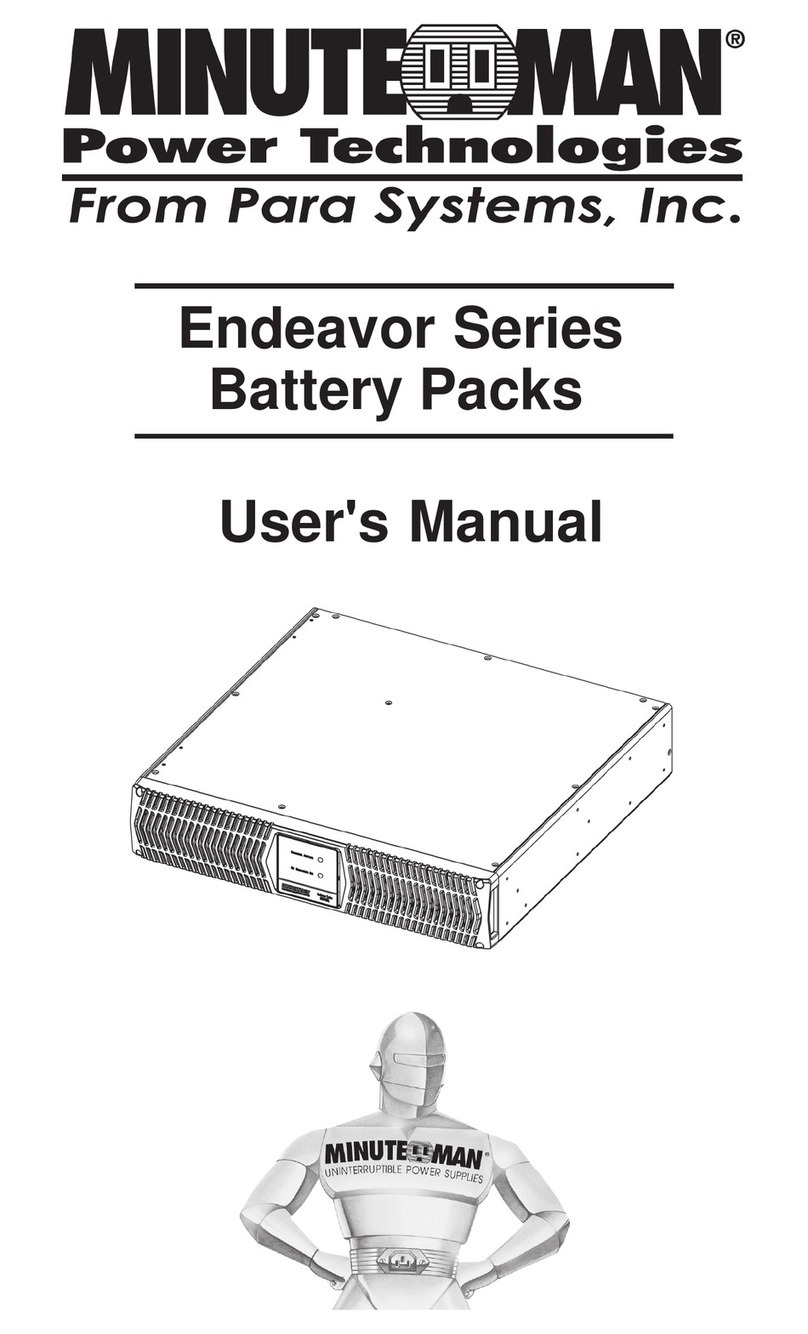
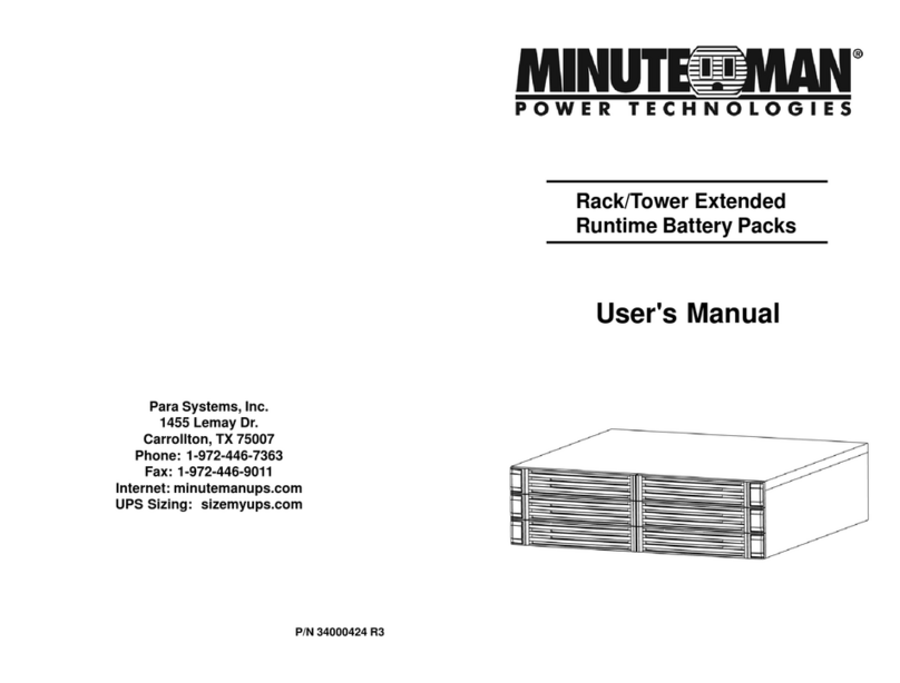
Minuteman BP24RTEXL User manual

User's Manual
Rack/Tower Extended
Runtime Battery Packs
Para Systems, Inc.
1455 Lemay Dr.
Carrollton, TX 75007
Phone: 1-972-446-7363
Fax: 1-972-446-9011
Internet: minutemanups.com
UPS Sizing: sizemyups.com
P/N34000424

1
© Copyright 2011
English
1. Introduction 2
2. Controls and Indicators 6
3. Installation 7
4. Replacing the Battery 12
5. Obtaining Service 16
6. Specifications 17
7. Limited Product Warranty 18
TABLE OF CONTENTS

3
2
English
WARNING: RiskofElectrical Shock. Hazardous livepartsinside
these Battery Packs are energized from the battery.
CAUTION! Tode-energizethe BatteryPack:
1. If the UPS is on press and release the Off/On button.
2. Disconnect the UPS from the wall outlet.
3. Turnoff the DC breaker onthe rear panel of theBattery Pack.
4. Disconnect the battery cable from the rear panel of the UPS.
5. To de-energizetheBattery Pack completely,disconnect the bat-
teries.
CAUTION! These Battery Packs are intended to be install in a
temperature controlled environment that is free of conductive con-
taminants. Selectalocation which will providegoodaircirculationfor
the Battery Pack and UPS at all times.
CAUTION! To reducethe risk ofelectrical shockwith the installa-
tion of these Battery Packs, with the UPS equipment and the con-
nected equipment, the user must ensure that the combined sum of
theAC leakage current does not exceed 3.5mA.
WARNING: These Battery Packs contains potentially hazardous
voltages. Do not attempt to disassemble the Battery Pack beyond
the battery replacement procedure. These Battery Packs contains
nouser serviceable parts. RepairsandBattery replacement mustbe
performedbyQUALIFIED SERVICEPERSONNELONLY.
Receiving Inspection
After removing your Battery Pack from its carton, it should be inspected for
damagethatmay have occurred inshipping. Immediatelynotifythecarrier and
placeofpurchase if any damageisfound. Warrantyclaimsfor damage caused
by the carrier will not be honored. The packing materials that your Battery
Packwas shipped inarecarefully designed tominimizeany shipping damage.
Inthe unlikely casethatthe Battery Packneedsto be returnedtothe manufac-
turer, please use the original packing material. Since the manufacturer is not
responsible for shipping damage incurred when the system is returned, the
originalpacking material isinexpensiveinsurance.
PLEASE SAVE THE PACKING MATERIALS!
English
IMPORTANT SAFETY INSTRUCTIONS
SAVE THESE INSTRUCTIONS !
Thankyou for purchasingthis power protectionproduct. Ithas been designed
andmanufacturedto provide manyyearsof trouble free service.
Please read this manual before installing your Endeavor and Enterprise Plus
Series Battery Pack, models BP24RTEXL, BP48RTEXL, BP36RTEXL,
BP72RTEXLasitprovidesimportantinformation that should be followedduring
installation and maintenance of the Battery Packs and batteries allowing you
to correctly set up your system for the maximum safety and performance.
Includedisinformation on customersupportandfactory service ifitisrequired.
Ifyouexperience a problemwiththe Battery Packs pleasereferto the Trouble-
shootingguidein this manualtocorrectthe problem orcollectenoughinforma-
tion so that the Technical Support Department can rapidly assist you.
Thissymbol indicates "ATTENTION"
This symbol indicates "Risk of Electrical Shock"
This symbol indicates "Direct Current Supply"
This symbol indicates "Equipment Grounding Conductor"
1. INTRODUCTION

5
4
English
NOTICE: This equipment has been tested and found to comply with
thelimitsfora ClassAcomputingdevice in accordancewiththe speci-
ficationsin SubpartJ of Part15ofFCC Rules andtheClassAlimits for
radionoiseemissionsfrom digital apparatus setoutintheRadio Interference of
the Canadian Department of Communications. These limits are designed to
providereasonableprotectionagainstsuch interference in a residentialinstalla-
tion. This equipment generates and uses radio frequency and if not installed
andused properly, thatis, in strictaccordancewith themanufacturer'sinstruc-
tions,this equipment maycauseinterference to radioandtelevision reception.
Ifthisequipmentdoes cause interferencetoradioortelevision reception, which
canbedetermined by turning theequipmentoffand on, theuserisencouraged
to try to correct the interference by one or more of the following measures:
Re-orientthereceivingantenna.
Relocatethe computer withrespect to thereceiver.
Movethecomputer away fromthereceiver.
Plugthe computer intoa different outletso that thecomputer and receiver
areon different branchcircuits.
Shieldedcommunications interface cables mustbeused with thisproduct.
WARNING: Changes or modifications to this unit not expressly ap-
proved by the party responsible for compliance could void the user's
authorityto operate theequipment.
Life Support Policy
Asa general policy,wedo not recommendthe use ofanyof our productsinlife
supportapplicationswhere failure ormalfunctionofthe product canbereason-
ablyexpected to causefailureof the lifesupportdevice or tosignificantlyaffect
its safety or effectiveness. We do not recommend the use of any of our prod-
ucts in direct patient care. We will not knowingly sell our products for use in
such applications unless it receives in writing assurances satisfactory to us
that (a) the risks of injury or damage have been minimized, (b) the customer
assumes all such risks, and (c) our liability is adequately protected under the
circumstances.
Examplesofdevicesconsidered to be lifesupportdevicesareneonatal oxygen
analyzers,nerve stimulators (whetherusedfor anesthesia, painrelief,or other
purposes), auto transfusion devices, blood pumps, defibrillators, arrhythmia
detectorsand alarms, pacemakers,hemodialysis systems, peritonealdialysis
systems,neonatal ventilator incubators,ventilatorsfor both adultsandinfants,
anesthesiaventilators, and infusion pumpsaswell as anyotherdevices desig-
nated as “critical” by the United States FDA.
English
WARNING: Qualified Service Personnel ONLY must perform
theInstallation and Servicingof theseBatteryPacks. MINUTEMAN
accepts no liabilities and is not limited to: injury to the Service Per-
sonnel,or damagesto;the BatteryPack, the UPS,or the connected
equipment caused by the incorrect installation or servicing of the
Battery Packs. These Battery Packs MUST be operated with their
respectiveUPS models,see the tablebelow:
BP24RTEXL
UPS
Model ED1000RM2U
ED1000RMT2U
BP72RTEXL
Model
E2000RM2U
E2000RM2UL
E3000RM2U
E3000RMT2U
ED3000RM2U
ED3000RMT2U
BP48RTEXL
ED1500RM2U
ED2000RM2U
ED1500RMT2U
ED2000RMT2U
BP36RTEXL
E750RM2U
E750RM2Up15
E1000RM2U
E1500RM2U
E1500RMT2U

7
6
English
INSTALLATION PLACEMENT
These Battery Packs are only intended to be install in an indoor temperature
controlledenvironmentthat is freeofconductivecontaminants. DO NOT oper-
ate the Battery Pack in: extremely dusty and/or unclean areas, locations near
heating devices, water or excessive humidity, or where the Battery Pack is
exposedto direct sunlight. Selecta location, whichwill provide goodair circu-
lation for the Battery Pack at all times.
Route power cords so they cannot be
walked on or damaged. Typical battery life is 3 to 5 years. Environmental
factors do affect battery life. High temperatures, and frequent, short duration
dischargeshave a negativeimpacton battery life.
INSTALLATION
Besure to readtheinstallation placementandall the cautionsbeforeinstalling
the Battery Pack. Place the Battery Pack in the final desired location and
completethe restof the installationprocedure.
WARNING! These Battery Packs are extremely heavy. Any time
theBattery Packhas tobe handled besure touse, enoughperson-
nel,strongsupportsandequipmenttosafelyhandletheBatteryPack.
ENVIRONMENTAL
Operating Temperature (max)
Operating/StorageHumidity
OperatingElevation
0to 40°C(+32 to+104°F)
95% Non-Condensing
0 to 3,000m (0 to +10,000 ft)
Storage Elevation 0 to 15,000m (0 to +50,000 ft)
Storage Temperature -15 to +45°C (+5 to +113°F)
3. INSTALLATION
English
REAR PANEL
A. The External Battery connector is for Daisy Chaining additional Battery Packs.
B. The DC Circuit Breaker connects and disconnects the DC bus voltage from the
BatteryPacktotheUPS. TheDCCircuitBreakerwilltripinthe event of a DC over-
current condition.
C. The External Battery cable is for connecting the Battery Pack to the UPS or Daisy
Chaining additional Battery Packs.
2. CONTROLS AND INDICATORS

9
8
English
TOWERCONFIGURATION
The tower configuration allows the user to install the Battery Pack in the up-
right position next to the UPS. The tower brackets are provided with the Bat-
tery Pack. WARNING: Use two or more people when installing the Battery
Pack. Use CAUTION, the Battery Pack is extremely heavy.
1. Oncethe location ofthe Battery Packhas been determined,lay theBattery
Pack on its side. (FIG. 1)
2. Attached the tower brackets to the Battery Pack with the retaining screws.
(FIG. 1)
3. Rotate the Battery Pack to the up-right position. Ensure the Battery Pack
is stable. (FIG. 2)
4. TheTower Configuration is complete. See Connecting the Battery Pack.
English
RACKMOUNTCONFIGURATION
TheBattery Pack comeswith mounting bracketsand rails forthestandard 19"
(46.5cm) 4-post rack. The screws for mounting the Battery Pack to the rack
are not included (screw size varies with rack size).
1. Mount the rails to the 4-post rack. (FIG. 1)
2. Locate the mounting bracket screw holes on the side panels of the Battery
Pack, at the front of the Battery Pack. (FIG. 2)
3. Align the mounting bracket with the mounting bracket screw holes. (FIG. 2)
4. Attach the mounting bracket with the retaining screws. (FIG. 2)
5. Install the Battery Pack onto the Rails and secure the Battery Pack to the
rackwith the retainingscrews.(FIG. 3) WARNING: Usetwoormorepeople
when installing the Battery Pack. Use CAUTION, the Battery Pack is ex-
tremely heavy. Do not move the rack after the units have been installed.
The rack maybe unstable due to the weight distribution.
6. The Rackmount Configuration is complete. See Connecting the Battery
Pack.
FIG. 1
FIG. 2
FIG. 3
FIG. 1 FIG. 2

11
10
English
DAISYCHAINING
(QUALIFIEDSERVICEPERSONNELONLY)
"DaisyChaining" meanshooking one Battery Pack toanother Battery Pack to
another Battery Pack, this chain could go on indefinitely. Follow the steps
below to Daisy Chain the Battery Packs.
1. Besure to readtheinstallation placement procedure,allof the cautionsand
the safety precautions before Daisy Chaining the Battery Pack(s).
2. Make sure that the DC circuit breakers on the rear panel of the Battery
Packs are in the Off position. CAUTION: If the Battery Pack's DC circuit
breaker is in the On position, the battery voltage will be present at the open
end of the Battery Pack's external battery cable and external battery con-
nector.
3. Turn the UPS off and disconnect the UPS's input power cord from theAC
wall outlet.
4. RemovetheExternalBatteryConnectorcoverfromtheUPS'srearpanel and
the additional Battery Packs.
5. Verify, before plugging the external battery cable into the UPS's external
battery connector or the Battery Pack's external connector that they mate
red to red and black to black.
6. Connect the external battery cable from the first Battery Pack to the exter-
nal battery connector on the UPS.
7. Connectthe externalbatterycable fromthe second BatteryPack to theex-
ternal battery connector on the first Battery Pack.
8. TurnALL of the DC circuit breakers on the rear panel of the Battery Packs
to the On position.
9. The Battery Packs are ready for normal operation, see the UPS User's
Manual for the normal startup of the UPS.
NOTE: ThereisnomaximumnumberforDaisyChainingtheDCbusvoltagefor
the Battery Packs.
CONNECTINGTHEBATTERYPACK
(QUALIFIEDSERVICEPERSONNELONLY)
NOTE: When using these Battery Packs the UPS must be configured so
that the UPS will report the correct estimated runtime in the SentryPlus
software or the SNMP card and to make the Battery capacity bar graph
LEDs display properly. See the SentryPlus software or the SNMP-NET
card User’s Manual to configure the UPS.
English
Number of External Battery Packs to enter in
the SentryPlus software and/or the SNMP card
BP24RTEXL 5
Model
BP36RTEXL 3
BP48RTEXL 3
BP72RTEXL 3
1. Besure to readtheinstallation placement procedure,allof the cautionsand
the safety precautions before connecting the Battery Pack(s).
2. Make sure that the DC circuit breaker on the rear panel of the Battery Pack
is in the Off position. CAUTION: If the Battery Pack's DC circuit breaker
is in the On position, the battery voltage will be present at the open end of
the Battery Pack's external battery cable and external battery connector.
3. Turn the UPS off and disconnect the UPS's input power cord from theAC
wall outlet.
4. Removethe External BatteryConnector cover fromthe UPS's rearpanel.
5. Verify, before connecting the Battery Pack's external battery cable into the
UPS's external battery connector, that they mate red to red and black to
black. NOTE: The red connector is the battery positive (+) and the black
connector is the battery negative (-). Connect the external battery cable
fromthe Battery Packtotheexternal battery connectoronthe UPS. NOTE:
If connecting more than one Battery Pack see Daisy Chaining.
6. Turn the DC circuit breaker on the rear panel of the Battery Pack to the On
position.
7. The Battery Packs are ready for normal operation, see the UPS User's
Manual for the normal startup of the UPS.

13
12
English
BATTERYREPLACEMENT PROCEDURE
(QUALIFIEDSERVICEPERSONNELONLY)
PLEASE READ THE CAUTIONSAND WARNINGS BEFOREATTEMPTING
TOREPLACETHEBATTERIES
Hot-swappable batteries mean that the batteries can be replaced without
poweringdown the wholeUPS system.
NOTE: Ifthereisapowerinterruptionwhilereplacing the hot-swappable batter-
ies, with the UPS on, the load will not be backed up. To hot-swap the Battery
Pack's batteries start with step number 6.
1. Turn off the equipment that is plugged into the output receptacles of the
UPS.
2. Press and release the Off button on the front panel to turn the UPS off.
3. Unplug the UPS'sAC power cord from the AC wall outlet.
4. Unplug the equipment from the output receptacles of the UPS.
5. Unplug the computer interface cable from the rear panel of the UPS.
6. Turn off all of the DC circuit breakers on the rear panel of all of the Battery
Packs.
7. Disconnect all of the external battery cables.
8. Removethe frontpanelretainingscrew cover plates. (FIG. 1)
9. Remove the front panel retaining screws. (FIG. 2)
10. Removethe front panel.
11. Remove the retaining screws for the battery retaining bracket. (FIG. 3)
12. Removethe batteryretainingbracket. (FIG.3)
13. Cut and remove all of the battery cable ties from the battery modules.
14. Disconnect the battery connectors (red and black) one from each battery
module. (FIG. 4)
15. One at a time grasp the battery pull tabs and gently pull the battery mod-
ules out of the Battery Pack and set on the floor. (FIG. 4)
NOTE: UseCaution, the batterymodules are heavy.
16. Removethe tapethat goes aroundthe battery module.
17. Remove the top half of the plastic battery tray.
18. Disconnect the battery positive (red) wires.
19. Disconnect the battery negative (black) wires.
20. Disconnect the battery jumper wires.
BP24RTEXL
BP48RTEXL
BatteryQty/Rating 20 - 12V9.0Ah
BP36RTEXL
BP72RTEXL
Model#
Replace the batteries with the same number and type as origi-
nally installed in the Battery Pack. These batteries have pres-
sure operated vents. These Battery Packs contain sealed non-
spillablemaintenance free leadacid batteries.
CAUTION:
Yuasa Part # REW45-12
CSB Part # HR1234W F2
18- 12V9.0Ah
English
WARNING! This Battery Pack contains potentially hazardous voltages. Do
not attempt to disassemble the Battery Pack beyond the battery
replacement procedure. These Battery Packs contain no user
serviceableparts. Repairsand Battery replacement mustbeper-
formedbyQUALIFIED SERVICEPERSONNELONLY.
Donotopen or mutilate batteries. Releasedelectrolyteisharmful
to the skin and eyes and may be toxic.
CAUTION:
(QUALIFIEDSERVICEPERSONNELONLY)
CAUTION: Do not dispose of batteries in a fire. The batteries may explode.
Thebatteries in thisBattery Pack arerecyclable. Dispose of the
batteriesproperly. The batteriescontainleadand pose ahazard
tothe environment andhumanhealth if notdisposed of properly.
Refer to local codes for proper disposal requirements or return
the battery to the supplier.
Althoughbatterysystemvoltagesare only24VDC,36VDC,48VDC
and 72VDC the battery system can still present a risk of electri-
calshock. Thesebatteries produce sufficientcurrenttoburn wire
ortoolsvery rapidly,producingmolten metal. Observethese pre-
cautionswhen replacing thebatteries:
1. Remove watches, rings, or other metal objects.
2. Use hand tools with insulated handles.
3.Wear protective eyegear(goggles), rubber glovesandboots.
4. Do not lay tools or other metal parts on top of batteries.
5. Disconnect the charging source prior to connecting or discon-
necting the battery terminals.
6.Determine ifthebattery isinadvertently grounded. If thebatt-
ery is, remove the source of the grounding. Contact with any
part of a grounded battery can result in an electrical shock.
The likelihood of such shock will be reduced, if such grounds
are removed during installation and maintenance.
CAUTION:
TheseBatteryPacks have an easytoreplacehot-swappable batteries. Please
read all of the WARNINGS and CAUTIONS before attempting to service the
batteries.
NOTE: Ifthereisapowerinterruptionwhile replacing the hot-swappable batter-
ies, with the UPS on, the load will not be backed up.
4. REPLACING THE BATTERY

15
14
English
FIG. 2
FIG. 3
FIG. 4
English
21. Remove the old batteries from the bottom half of the plastic battery tray.
22. Installthenew batteries intothebottom half oftheplasticbattery tray inthe
same position as the original batteries.
23. Verify proper polarity. Re-install the battery jumper wires on the new
batteries.
24. Verifyproper polarity. Reconnect thebattery negative(black) wires.
25. Verifyproper polarity. Reconnect thebattery positive(red) wires.
26. Install top half of the plastic battery tray onto the batteries.
27. Tape thebattery module together.
28. Slide the battery modules into the Battery Pack.
29. Secure the battery cables with the battery cable ties.
30. Verify proper polarity. Reconnect the battery connectors (red and black).
NOTE: Some sparking might occur, this is normal.
31. Re-install the battery retaining bracket. (FIG. 5)
32. Re-install the retaining screws for the battery retaining bracket. (FIG. 5)
33. Re-install the front panel on the Battery Pack.
34. Re-install the front panel retaining screws. (FIG. 6)
35. Re-installthe front panelretainingscrew coverplates. (FIG. 7)
36. Reconnect all of the external battery cables.
37. Turnon allof the DCcircuit breakerson the rear panel ofall of the Battery
Packs.
38. Properly dispose of the old batteries at an appropriate recycling facility or
return them to the supplier in the packing material for the new batteries.
39. The Battery Pack is ready for normal operation.
NOTE: Ifthe UPS hasaWeak/BadBatteryAlarm after replacing the batteries,
the user must initiate a self test to clear the Weak/Bad Battery Alarm. To
initiate a self test see section 4 "SELF TEST" in the UPS's User's Manual.
FIG. 1
FIG. 5
FIG. 6
FIG. 7

17
16
English
Battery Type
24VDC
Typical Recharge Time
BP24RTEXL
ModelNumber
SYSTEMSPECIFICATIONS
Format Rack/Tower Convertible
BATTERYSYSTEM
Typical Battery Life
System Current 40 Amps
20 - 12V9.0Ah
Battery Qty/Rating
BP72RTEXL
System Voltage
Sealed,Non-Spillable,MaintenanceFree,Value Regulated,LeadAcid
3-5 years, depending on discharge cycles and ambient temperature
24-hours from total discharge
72VDC
PHYSICAL
Weight - Net
Size - Net
L X W X H
Size - Shipping
L X W X H
Weight - Shipping
26.8 x 17.3 x 5.2"
680 x 440 x 132 mm
35.8 x 22.0 x 10.7"
909 x 560 x 272 mm
148.2 lbs
67.2 Kgs
138.9 lbs
63.0 Kgs
BP48RTEXL
48VDC
127.9 lbs
58.0 Kgs
137.1 lbs
62.2 Kgs
ENVIRONMENTAL
Operating Temperature
Operating/Storage
Humidity
OperatingElevation
0to 40°C(+32 to+104°F)
95% Non-Condensing
0 to 3,000m (0 to +10,000 ft)
Storage Elevation 0 to 15,000m (0 to +50,000 ft)
Storage Temperature -15 to +45°C (+5 to +113°F)
BP36RTEXL
36VDC
18 - 12V9.0Ah
6. SPECIFICATIONS
English
IF THE UPS REQUIRES SERVICE
1.Use the TROUBLESHOOTING sectionto eliminate obviouscauses.
2. Verify there are no circuit breakers tripped. Atripped circuit breaker is the
most common problem.
3. Call your dealer for assistance. If you cannot reach your dealer, or if they
cannot resolve the problem callorfaxMINUTEMANTechnical Support atthe
following numbers; Voicephone (972) 446-7363,FAX line(972)446-9011 or
visitourWebsiteat www.minutemanups.comthe"DiscussionBoard". Please
have thefollowinginformation available BEFOREcallingtheTechnical Sup-
port Department.
A.Your name and address.
B. Where and when the unit was purchased.
C.All of the model information about your Battery Pack and UPS.
D.Any information on the failure, including LEDs that may be illuminated.
E.Adescription of the protected equipment, including model numbers if
possible.
F.Atechnician will ask you for the above information and, if possible, help
solveyour problem overthephone. Intheevent that theunitrequiresfact-
ory service, the technician will issue you a Return MaterialAuthorization
Number(RMA #).
G.IftheBattery Pack is underwarranty, therepairswillbedoneatno charge.
If not, there will be a charge for repair.
4. Pack the Battery Pack in its original packaging. If the original packaging is
no longer available,ask theTechnicalSupportTechnician aboutobtaininga
new set. It is important to pack the Battery Pack properly in order to avoid
damage in transit.Never useStyrofoam beadsfor a packingmaterial.
A. Include a letter with your name, address, day time phone number, RMA
number,acopyofyouroriginal sales receipt, andabrief description of the
problem.
5. Mark the RMA # on the outside of all packages. The factory cannot accept
any package without the RMA # marked on the outside.
6. Return the Battery Pack by insured, prepaid carrier to:
Para Systems Inc.
MINUTEMANUPS
1455LeMayDrive
Carrollton,TX75007
ATTN:RMA# _______
5. OBTAINING SERVICE

18
English
Para Systems Inc. (Para Systems) warrants this equipment, when properly applied
and operated within specified conditions, against faulty materials or workmanship
for a period of three years from the date of purchase. For equipment sites within the
United States and Canada, this warranty covers repair or replacement of defective
equipment at the discretion of Para Systems. Repair will be from the nearest autho-
rized service center. Replacement parts and warranty labor will be borne by Para
Systems. For equipment located outside of the United States and Canada, Para
Systems only covers faulty parts. Para Systems products repaired or replaced
pursuant to this warranty shall be warranted for the unexpired portion of the warranty
applying to the original product. This warranty applies only to the original purchaser
who must have properly registered the product within 10 days of purchase.
The warranty shall be void if (a) the equipment is damaged by the customer, is
improperly used, is subjected to an adverse operating environment, or is operated
outside the limits of its electrical specifications; (b) the equipment is repaired or
modified by anyone other than Para Systems or Para Systems approved personnel;
or (c) has been used in a manner contrary to the product’s User's Manual or other
written instructions.
Any technical advice furnished before or after delivery in regard to use or application
of Para Systems’s equipment is furnished without charge and on the basis that it
represents Para Systems’s best judgment under the circumstances, but it is used
at the recipient’s sole risk.
EXCEPTAS PROVIDED HEREIN,PARASYSTEMSMAKESNOWARRANTIES,EX-
PRESSED OR IMPLIED, INCLUDING WARRANTIES OF MERCHANTABILITYAND
FITNESS FOR A PARTICULAR PURPOSE. Some states do not permit limitation of
implied warranties; therefore, the aforesaid limitation(s) may not apply to the pur-
chaser.
EXCEPTAS PROVIDED ABOVE, IN NO EVENT WILLPARASYSTEMS BE LIABLE
FORDIRECT, INDIRECT,SPECIAL, INCIDENTAL,ORCONSEQUENTIALDAMAGES
ARISINGOUTOFTHE USE OFTHISPRODUCT, EVENIFADVISED OFTHEPOSSI-
BILITY OF SUCH DAMAGE. Specifically, Para Systems is not liable for any costs,
such as lost profits or revenue, loss of equipment, loss of use of equipment, loss of
software, loss of data, cost of substitutes, claims by third parties, or otherwise. The
sole and exclusive remedy for breach of any warranty, expressed or implied, con-
cerning Para Systems’s products and the only obligation of Para Systems hereun-
der, shall be the repair or replacement of defective equipment, components, or
parts; or, at Para Systems’s option, refund of the purchase price or substitution with
an equivalent replacement product. This warranty gives you specific legal rights and
you may also have other rights which vary from state to state.
Longer term warranties are available at an additional cost. Contact Para Systems
(1-972-446-7363) for details.
7. LIMITED PRODUCT WARRANTY
This manual suits for next models
3
Table of contents
Other Minuteman Batteries Pack manuals
Popular Batteries Pack manuals by other brands

Altius
Altius AS-5KW-LB2 installation manual

Parkside
Parkside 339125 1910 operating instructions

Gogen
Gogen PB 80003 W installation manual

Parkside
Parkside 302268 operating instructions

True blue power
True blue power TB40 Series Installation manual and operating instructions

Mastervolt
Mastervolt 1603 manual