Minuteman BP24XL User manual

Para Systems, Inc.
1455 Lemay Dr.
Carrollton, TX 75007
Phone: 1-972-446-7363
Fax: 1-972-446-9011
Internet: minutemanups.com
UPS Sizing: sizemyups.com
P/N 34000532 R1
User's Manual
Encompass BPXL
Battery Packs

1
1. Introduction 2
2. Rear Panel 6
3. Installation 7
4. Obtaining Service 11
5. Replacing the Battery 12
6. Specifications 16
7. Limited Product Warranty 17
A1. Declaration of Conformity 18
Table Of Contents

23
Thankyouforpurchasingthispowerprotectionproduct. Ithasbeendesigned
and manufactured to provide many years of trouble free service. Please read
thismanualbeforeinstallingyourEncomapssBPXLBatteryPackseries,models
BP24XL, BP48XL,BP72XL as it provides important information thatshouldbe
followedduring the installation and the maintenance of the Battery Pack allow-
ing you to correctly set up your system for the maximum safety and perfor-
mance. Included is information on customer support and factory service, if it
is required. If you experience a problem with the Battery Pack please refer to
the Obtaining Service in this manual to correct the problem or collect enough
information so that the Technical Support Department can assist you.
SAVE THESE INSTRUCTIONS -This manual containsimportant instructions
that should be followed during the installation and the maintenance of the
Battery Pack and the batteries.
CAUTION! Themaximum ambient operatingtemperaturefor this BatteryPack
series is 40°C (“0 ~ 40°C” for Ambient Operation).
Theexternal vents and openings on theBatteryPack are provided for ven-
tilation. To ensure reliable operation of the Battery Pack and to protect the
BatteryPack from overheating, these vents and openings mustnotbeblo-
cked or covered. Do not insert any object into any of the vents or opening
thatmayhindertheventilation.
Installthe Battery Pack in awellventilatedarea, away from excess moistu-
re,heat,dust,flammablegasorexplosives.
Leave adequate space (at least 20cm) in the front and at the rear of the
Battery Pack for proper ventilation.
Do not install the Battery Pack with its front or rear panel facing down at
any angle.
Do not install the Battery Pack laying on its side panels.
Before usage, you must allow the Battery Pack to adjust to room temper-
ature (20°C~25°C or 68°F~77°F) for at least one hour to avoid moisture
condensing inside the Battery Pack.
IMPORTANT SAFETYINSTRUCTIONS
SAVE THESE INSTRUCTIONS !
CONSIGNES DE SÉCURITÉ IMPORTANTES
SAUVEGARDEZ CES CONSIGNES!
Veuillez lire ce manuel avant l'installation de l'onduleur modèles BP24XL,
BP48XL,BP72XL. Il contientdel'information importante qui doitêtrerespectée
au cours de l'installation et de l'entretien de l'onduleur et des batteries. Cette
informationvous permettra de correctement installer lesystèmepouratteindre
sonrendement maximum en toute sécurité.
Chapter 1: Introduction
WARNING: Risk of Electrical Shock. Hazardous live parts inside these
Battery Packs are energized from the battery.
WARNING: TheseBattery Packscontainspotentially hazardous voltages.
Do not attempt to disassemble the Battery Pack beyond the battery replace-
ment procedure. These Battery Packs contains no user serviceable parts.
Repairs and battery replacement must be performed by QUALIFIED SER-
VICE PERSONNEL ONLY.
CAUTION! This Battery Pack series is ONLYintended to be installed in an
indoortemperature controlled environment that is free of conductive contami-
nants. This Battery Pack series is not intended for use in a computer room as
defined in the Standard for the Protection of Electronic Computer/Data Pro-
cessingEquipmentANSI/NFPA75.
CAUTION! DO NOT install these Battery Packs with its front or rear panel
facing down at any angle or laying on its side panels.
CAUTION! To de-energize the Battery Pack:
1. If the UPS is On press and release the Off button.
2. Disconnect the UPS from the wall outlet.
3. Turn off the DC breaker on the rear panel of the Battery Pack.
4. Disconnect the battery cable from the rear panel of the UPS.
5. To de-energize the Battery Pack completely, disconnect the batteries.
WARNING: Qualified Service Personnel ONLY must perform the Installa-
tion and Servicing of these Battery Packs. MINUTEMAN accepts no liabilities
and is not limited to: injury to the User or Service Personnel, or damages to;
the Battery Pack, or the connected equipment caused by the incorrect instal-
lation or servicing of the Battery Pack and/or UPS system. These Battery
Packs MUST be operated with their respective UPS models, see the table
below:
UPS
BP BP72XL
EC3000LCD
BP24XL BP48XL
EC1000LCD EC1500LCD
EC2000LCD

45
NOTICE: Thisequipment has been tested and found to comply with the limits
for a ClassA computing device in accordance with the specifications in Sub-
part J of Part 15 of FCC Rules and the ClassAlimits for radio noise emissions
from digital apparatus set out in the Radio Interference of the Canadian De-
partment of Communications. These limits are designed to provide reason-
able protection against such interference in a residential installation. This
equipment generates and uses radio frequency and if not installed and used
properly, that is, in strict accordance with the manufacturer's instructions, this
equipment may cause interference to radio and television reception. If this
equipmentdoescauseinterference to radio or television reception, which can
be determined by turning the equipment off and on, the user is encouraged to
try to correct the interference by one or more of the following measures:
Re-orientthe receivingantenna.
Relocatethecomputerwithrespect to the receiver.
Movethe computer away from thereceiver.
Plugthecomputerintoadifferent outlet so that the computer and receiver
areon different branch circuits.
Shieldedcommunications interface cables must be used withthisproduct.
WARNING: Changes or modifications to this unit not expressly approved
by the party responsible for compliance could void the user's authority to
operatethe equipment.
Life Support Policy
As a general policy, we do not recommend the use of any of our products in
life support applications where failure or malfunction of the product can be
reasonably expected to cause failure of the life support device or to signifi-
cantly affect its safety or effectiveness. We do not recommend the use of any
of our products in direct patient care. We will not knowingly sell our products
for use in such applications unless it receives in writing assurances satisfac-
tory to us that (a) the risks of injury or damage have been minimized, (b) the
customer assumes all such risks, and (c) our liability is adequately protected
under the circumstances.
Receiving Inspection
After removing your Battery Pack from its carton, it should be inspected for
damage that may have occurred in shipping. Immediately notify the carrier
and place of purchase if any damage is found. Warranty claims for damage
caused by the carrier will not be honored. The packing materials that your
Battery Pack was shipped in are carefully designed to minimize any shipping
damage. Inthe unlikely case that the Battery Pack needs to be returned to the
manufacturer, please use the original packing material. Since the manufac-
turer is not responsible for shipping damage incurred when the system is
returned, the original packing material is inexpensive insurance. PLEASE
SAVE THE PACKING MATERIALS!
© COPYRIGHT 2018 BY PARA SYSTEMS, INC.
All Rights Reserved.All rights of this User's Manual (“Manual”), including but
not limited to the content, information, and figures are solely owned and re-
served by Para Systems, Inc. (“Para Systems”). The Manual can only be
applied to the operation or the use of this product. Any disposition, duplica-
tion, dissemination, reproduction, modification, translation, extraction, or us-
age of this Manual in whole or in part is prohibited without the prior written
permission of Para Systems. Given that Para Systems will continuously im-
prove and develop the product, changes may be made to the information in
thisManual at any time without obligation to notify any person of such revision
or changes. Para Systems will make all possible efforts to secure the accu-
racy and the integrity of this Manual. Para Systems disclaims any kinds or
forms of warranty, guarantee, or undertaking, either expressly or implicitly,
including but not limited to the completeness, faultlessness, accuracy, non-
infringement,merchantabilityor fitness for a particular purpose of the Manual.

67
1. The DC Breaker connects and disconnects the DC bus voltage from the Battery
Pack to the UPS. The DC Breaker will trip in the event of a DC overcurrent condi-
tion.
2. TheExternal Battery connector is for Daisy Chaining additionalBattery Packs.
3. TheExternal Batterycable is for connecting the Battery Pack to theUPS or Daisy
ChainingadditionalBattery Packs.
INSTALLATION PLACEMENT
This Battery Pack series is ONLYintended to be installed in an indoor tem-
perature controlled environment that is free of conductive contaminants. DO
NOToperatetheBatteryPackin:extremelydustyand/oruncleanareas,loca-
tions near heating devices, water or excessive humidity, or where the Battery
Pack is exposed to direct sunlight. Select a location, which will provide good
air circulation for the Battery Pack at all times.
Route the battery cables so
theycannotbewalked on or damaged. This Battery Pack series is not for use
in a computer room as defined in the Standard for the Protection of Electronic
Computer/DataProcessing EquipmentANSI/NFPA75. Typical battery life is 3
to 5 years. Environmental factors do affect battery life. High temperatures,
poor utility power, and frequent, short duration discharges have a negative
impact on battery life.
INSTALLATION
Besure to read the installation placement and all the cautions before installing
the Battery Pack. Place the Battery Pack in the final desired location and
completethe rest of the installation procedure.
WARNING! These Battery Packs are extremely heavy. Anytime the Battery
Pack has to be handled be sure to use, enough personnel, strong supports
and equipment to safely handle the Battery Pack.
CAUTION! DO NOT install these Battery Packs with its front or rear panel
facing down at any angle or laying on its side panels.
Chapter 2: Rear Panel Chapter 3: Installation
NOTE: WhenusingtheseBatteryPacks, the UPS must be configured so that
theUPS will report the correct estimated runtime on the LCD screen and in the
PowerMonitoringsoftwareand/ortheSNMP card. See the Power Monitoring
software or the SNMP card’s User's Manual to configure the UPS.
Operating Temperature (Maximum): 0 to 40°C (+32 to +104°F)
Operating Elevation: 0 to 3,000m (0 to +10,000 ft)
Operating and Storage Relative Humidity: 10% to 90%, non-condensing
Storage Temperature: -15 to +45°C (+5 to +113°F)
Storage Elevation: 0 to 15,000m (0 to +50,000 ft)

89
CONNECTING THE BATTERYPACK
NOTE: WhenusingtheseBatteryPacks, the UPS must be configured so that
theUPS will report the correct estimated runtime on the LCD screen and in the
PowerMonitoringsoftwareand/ortheSNMP card. See the Power Monitoring
software or the SNMP card’s User's Manual to configure the UPS.
1. Be sure to read the installation placement procedure, all of the cautions
and the safety precautions before connecting the Battery Pack.
2. Make sure that the DC breaker on the rear panel of the Battery Pack is in
the off position. CAUTION: If the Battery Pack's DC breaker is in the on
position, the battery voltage will be present at the open end of the Battery
Pack's external battery cable and the external battery connector.
3. If the UPS is on, turn the UPS off and disconnect the UPS's input power
cord from theAC wall outlet.
4. Remove thescrewfrom the external battery connector's coverplateon the
rear panel of the UPS and the rear panel of the Battery Pack.
5. Install the battery cable strain relief (C1) onto the external battery cable.
Step 1: Push the strain relief onto the external battery cable connector.
Step 2: Push the strain relief forward.
6. Verify, before connecting the Battery Pack's external battery cable into
theUPS's external battery connector,thatthebattery connectors mate red
toredandblacktoblack. NOTE: Theredconnectoristhebatterypositive
(+) and the black connector is the battery negative (-).
7. Connect the external battery cable from the Battery Pack to the external
battery connector on the UPS and secure the strain relief with the retain-
ing screw. NOTE: If connecting more than one Battery Pack see Daisy
Chaining.
8. Turn the DC breaker on the rear panel of the Battery Pack to the on pos-
ition.
DAISYCHAINING
"DaisyChaining" means connecting one Battery Pack to another Battery Pack
to another Battery Pack, this chain could go on indefinitely. Follow the steps
below to Daisy Chain the Battery Packs:
1. Be sure to read the installation placement procedure, all of the cautions
and the safety precautions before connecting the Battery Packs.
2. Make sure that the DC breakers on the rear panels of the Battery Packs
are in the off position. CAUTION: If the Battery Pack's DC breaker is in
the on position, the battery voltage will be present at the open end of the
Battery Pack's external battery cable and the external battery connector.
3. If the UPS is on, turn the UPS off and disconnect the UPS's input power
cord from theAC wall outlet.
4. Remove thescrewfrom the external battery connector's coverplateon the
rear panel of the UPS and the rear panel of all of the Battery Packs.
5. Install the battery cable strain reliefs (C1) onto all of the the external batt-
ery cables.
Step 1: Push the strain relief onto the external battery cable connector.
Step 2: Push the strain relief forward.
9. The BatteryPack is readyfor normal operation,see the UPSUser's Manual
for the normal startup of the UPS.

10 11
Chapter 4: Obtaining Service
IF THE BATTERYPACK REQUIRES SERVICE
1. Use the followingtoeliminateobviouscauses.
2. Verify there are no tripped circuit breakers and that the batteries are good.
A tripped circuit breaker and defective batteries are the most common iss-
ues.
3. Call your dealer for assistance. If you cannot reach your dealer, or if they
cannotresolve the issue call or faxtheTechnicalSupport departmentatthe
following numbers; Voice phone (972) 446-7363, FAX line (972) 446-9011
or visit our Web site at www.minutemanups.com the "Discussion Board".
Before calling the Technical Support Department have the following infor-
mationavailable:
a) Contact name and address.
b) Where and when the unit was purchased.
c) All of the model information about your unit.
d) The serial number of your unit.
e) Any information on the failure, including LEDs that may be illuminated
or error codes displayed.
f) A description of the protected equipment including model numbers, if
possible.
g) A technician will ask you for the above information and if possible,
helpsolve the issue over the phone. In the event that the unit requires
factoryservice,theTechnicalSupport Representativewill issue youa
Return MaterialAuthorization Number (RMA#). NOTE: We must
have the model number and the serial number of the product to
issue an RMA #.
h) If the unit is under warranty, the repairs will be done at no charge. If
the unit is not under warranty there will be a charge for the repair.
4. Pack the unit in its original packaging. If the original packaging is no lon-
geravailable,asktheTechnicalSupport Representative about obtaininga
new set. It is important to pack the unit properly in order to avoid damage
intransit. Never use Styrofoam beads for a packing material.
a) Include a letter with your name, address, day time phone number,
RMAnumber, a copy of your original sales receipt, and a brief desc-
ription of the problem.
5. Mark the RMA # on the outsideofallpackages. Thefactorycannotaccept
any package without the RMA # marked on the outside.
6. Return the unit by insured, prepaid carrier to:
Para Systems Inc.
MINUTEMANUPS
1809 W. Frankford Road, Suite 150
Carrollton,TX 75007
ATTN: RMA# _______
6. Verify, before plugging the external battery cable into the UPS's external
battery connector and the Battery Pack's external battery connector that
they mate red to red and black to black. NOTE: The red connector is the
battery positive (+) and the black connector is the battery negative (-).
7. Connect the external battery cable from the first Battery Pack to the exter-
nal battery connector on the UPS and secure the strain relief with the ret-
aining screw.
8. Connect the external battery cable from the second Battery Pack to the e-
xternal battery connector on the first Battery Pack and secure the strain
relief with the retaining screw.
9. Turnall of the DC breakers on the rearpanelsof all of the Battery Packs to
the on position.
10. The Battery Packs are ready for normal operation, see the UPS User's
Manual for the normal startup of the UPS.

12 13
BATTERYREPLACEMENT PROCEDURE
PLEASE READ THE CAUTIONS AND WARNINGS BEFORE ATTEMPTING
TO REPLACE THE BATTERY MODULES
Thebattery modules in theBattery Packs can bereplaced without powering down
thewhole UPS system.
1. Turn off all of the DC breakers on the rear panel of all of the Battery Packs.
2. Removetheretaining screwfromthe batterycable strainreliefon therearpanel
of the UPS and the Battery Packs.
3. Disconnectall ofthe external battery cables.
4. Removethe Battery Pack's cover screws.
5. Remove the cover and set it aside.
6. Pressdown to unlock the battery connector holders on the right hand side of
theBattery Pack and on theleft hand sideof the Battery Pack. (FIG. 1)
7. Disconnectthe battery connectors (red and black)from each of thebattery
modulesoneon theright handside of theBattery Packand oneonthe lefthand
side of the Battery Pack. (FIG. 1)
8. Removethe fastnersfrom the battery retaining bracketson the righthand side
ofthe Battery Pack and on the left hand side ofthe Battery Pack. (FIG. 2)
9. Removethe batteryretaining brackets.
10. Graspone of the batterymodule and gently pullit out of theBattery Pack and
set it aside.
11. Graspthe other battery moduleand gently pull itof the Battery Pack and set it
aside.
NOTE: UseCaution, the battery modules are heavy.
12. Slidethe new battery modulesinto the Battery Pack.
13. Re-installall of thebattery retaining brackets.
14. Re-installall of thefastners for thebattery retaining brackets.
15. Verifyproper polarity. Reconnect all of the battery connectors (red and black)
together.
NOTE: Some sparking may occur this is normal.
16. Relockall of thebattery connector holders.
17. Re-installthe cover.
18. Re-installthe coverscrews.
19. Reconnectall of the external batterycables.
20. Re-installthe retaining screws for all of thebattery cable strain reliefs.
21. Turn on all of the DC breakers on the rear panel of all of the Battery Packs.
22. Properly dispose of the old batteries at an appropriate recycling facility or re-
turnthem to the supplierin the packing materialfor the new batteries.
23. The Battery Pack is ready for normal operation.
NOTE: Ifthe UPS has aWeak/BadBatteryAlarm after replacing thebattery mod-
ules, the user must initiate a self test to clear the Weak/Bad Battery Alarm. To
initiate a self test see section 4 "USER INVOKED BATTERYTEST" in the UPS's
User'sManual.
BP72XL
BP24XL BP48XL
Chapter 5: Replacing the Battery
InternalBattery
ModulePart# BM0079 BM0080 BM0081
Model#
WARNING! This Battery Pack contains potentially hazardous voltages. Do
not attempt to disassemble the Battery Pack beyond the battery replacement
procedure. This Battery Pack contains no user serviceable parts.
CAUTION: Donotopenormutilatebatteries. Releasedelectrolyteisharmful
to the skin and eyes and may be toxic.
CAUTION: Do not dispose of batteries in a fire. The batteries may explode.
The batteries in this Battery Pack are recyclable. Dispose of the batteries
properly. The batteries contain lead and pose a hazard to the environment
and human health if not disposed of properly. Refer to local codes for proper
disposal requirements or return the battery to the supplier.
CAUTION: The battery system can present a risk of electrical shock. These
batteries produce sufficient current to burn wire or tools very rapidly, produc-
ingmoltenmetal. Observetheseprecautions when replacing the batteries:
1. Remove watches, rings, or other metal objects.
2. Use handtoolswithinsulated handles.
3. Wear protective eye gear (goggles), rubber gloves and boots.
4. Do not lay tools or other metal parts on top of batteries.
5. Disconnect the charging source prior to connecting or disconnecting the
batteryterminals.
6. Determine if the battery is inadvertently grounded. If the battery is, remove
the source of the grounding. Contact with any part of a grounded battery
can result in an electrical shock. The likelihood of such shock will be redu-
ced, if such grounds are removed during installation and maintenance.
Please read all of the WARNINGS and CAUTIONS before attempting to ser-
vice the batteries. Typical battery life is 3 to 5 years. Environmental factors
do affect battery life. High temperatures, poor utility power, and frequent,
short duration discharges have a negative impact on battery life.
CAUTION: Replace batteries with the same number and type as originally
installed in the Battery Pack. These batteries have pressure operated vents.
TheseBatteryPackscontainsealednon-spillablemaintenance-freeleadacid
batteries.
QUALIFIED SERVICE PERSONNEL ONLY QUALIFIED SERVICE PERSONNEL ONLY

14 15
FIG. 1 FIG. 2

16 17
ParaSystems,Inc. (Para Systems) warrantsthisequipment, when properly appliedand
operated within specified conditions, against faulty materials or workmanship for a pe-
riod of three years from the date of purchase. For equipment sites within the United
StatesandCanada,thiswarranty covers depot repairor replacement ofdefectiveequip-
mentatthe discretion of ParaSystems. Depotrepair will be fromthenearest authorized
service center. The customer pays for shipping the product to Para Systems. Para
Systems pays ground freight to ship the product back to the customer. Replacement
partsandwarranty labor willbeborne by ParaSystems. For equipment located outside
oftheUnited Statesand Canada, Para Systemsonly covers faulty parts. ParaSystems
products that are depot repaired or replaced pursuant to this warranty shall only be
warrantedforthe unexpired portion of thewarrantyapplying to the originalproduct. This
warranty applies only to the original purchaser who must have properly registered the
productwithin 10 days of purchase.
Thewarranty shall be void if (a) the equipment isdamaged by the customer,is improp-
erlyused, is subjected to anadverse operating environment, or isoperated outside the
limitsof its electrical specifications;(b) the equipmentis repaired ormodified by anyone
otherthan Para Systems or Para Systems approved personnel; or (c) has been usedin
amanner contrary to the product’sUser's Manual or other written instructions.
Anytechnical advice furnished before orafter delivery in regard touse or application of
ParaSystems’equipment is furnished withoutchargeand on the basisthatit represents
Para Systems’ best judgment under the circumstances, but it is used at the recipient’s
solerisk.
EXCEPTASPROVIDED HEREIN, PARASYSTEMSMAKES NO WARRANTIES, EX-
PRESSEDOR IMPLIED,INCLUDINGWARRANTIESOFMERCHANTABILITYANDFIT-
NESSFORAPARTICULARPURPOSE. Somestatesdonotpermitlimitationofimplied
warranties;therefore, the aforesaidlimitation(s)may not apply to the purchaser.
EXCEPTAS PROVIDED ABOVE, IN NO EVENT WILLPARA SYSTEMS BE LIABLE
FORDIRECT,INDIRECT,SPECIAL, INCIDENTAL,ORCONSEQUENTIALDAMAGES
ARISINGOUTOFTHEUSE OF THIS PRODUCT,EVENIFADVISEDOFTHEPOSSI-
BILITYOFSUCH DAMAGE. Specifically,Para Systems isnotliable for anycosts,such
as; labor for on-site installation, on-site maintenance or on-site service, lost profits or
revenue,lossof equipment, loss ofuse of equipment, lossof software, loss ofdata, cost
ofsubstitutes, claims by third parties, or otherwise. The sole and exclusive remedy for
breachof any warranty,expressed or implied, concerning ParaSystems’products and
theonly obligation of Para Systems hereunder,shall bedepot repair orreplacement of
defective equipment, components, or parts; or, at Para Systems’ option, refund of the
purchase price or substitution with an equivalent replacement product. This warranty
givesyou specific legalrights and you may alsohave other rightswhich vary from state
tostate.
No employee, salesman, or agent of Para Systems is authorized to add to or vary the
terms of this warranty.
Pleasego to our web site at www.minutemanups.com/support tofill out the Warranty
Registration.
Chapter 7: Limited Product Warranty
BatteryType
ModelNumber SYSTEM SPECIFICATIONS
Format Tower
BATTERYSYSTEM
ChargeCurrent 2.4Amps(MAX)
Typical Battery Life
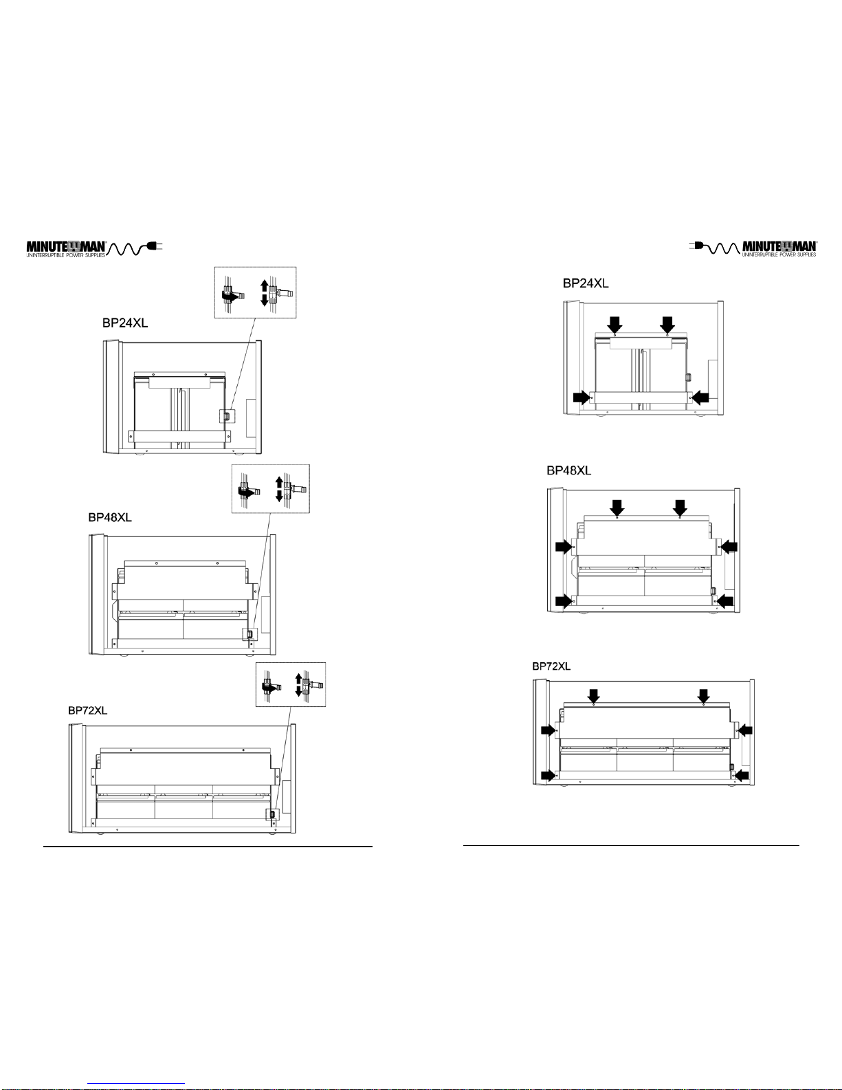
BatteryModule
BP72XL
System Voltage
Sealed, Non-Spillable, Maintenance Free, Valve Regulated, Lead Acid
3-5years, depending on discharge cycles and ambient temp
72VDC
BM0081
Weight - Net
Size - Net L X W X H
(rackmount bracket installed)
Size - Shipping
L X W X H
Weight- Shipping
17.4 x 6.8 x 11.4"
440x171x288mm
21.9 x 10.5 x 15.9"
555x266x403mm
REGULATORYCOMPLIANCE
SafetyandApprovals
35.3 lbs
16.0 Kgs
32.6 lbs
14.8 Kgs 60.6 lbs
27.5 Kgs
63.1 lbs
28.6 Kgs
14.1 x 6.1 x 10.2"
356.2x154x258.2mm
92.4 lbs
41.9 Kgs
89.3 lbs
40.5 Kgs
BM0079 BM0080
24VDC 48VDC
BP24XL BP48XL
Chapter 6: Specifications
cULus(UL1778 5th Edition &CSA 22.2 no. 107.3-14 / R: 2014),
FCC ClassA, CE certified, RoHS2 (EU Directive 2011/65/EU &
2015/863/EU)
17.8 x 10.3 x 15.1"
450.2x260x383mm
23.4 x 6.8 x 11.4"
594.2x171x288mm
27.9 x 11.2 x 16.3"
708.5x284x412.5mm
TypicalRecharge Time
OutputCurrent 40Amps(MAX)
24-hoursfrom total discharge
PHYSICAL
ENVIRONMENTAL
OperatingTemperature
Operating/Storage
Humidity
OperatingElevation
0 to 40°C (+32 to +104°F)
10-90%Non-Condensing
0 to 3,000m (0 to +10,000 ft)
Storage Elevation 0 to 15,000m (0 to +50,000 ft)
StorageTemperature -15 to +45°C (+5 to +113°F)

18 19
Notes:
A1. DECLARATION OF CONFORMITY
Application of Council Directive(s): 2014/35/EU
Manufacturer’s Name: Para Systems, Inc. (MINUTEMAN UPS)
Manufacturer’sAddress:1455 LeMay Drive
Carrollton,Texas 75007 USA
Type of Equipment: Uninterruptible Power Supplies (UPS)
Model No: BP24XL, BP48XL, BP72XL
I hereby declare that the equipment specified above conforms to the above
Directive(s).
Place:Carrollton,Texas,USA Date: September 3, 2018
RobertCalhoun
(Name) ManagerEngineering
(Position)
Year of Manufacture: Beginning September 2018
Standard(s) to which Conformity is declared: EN62040-2, IEC61000-2-2
IEC61000-4-2, IEC61000-4-3, IEC61000-4-4, IEC61000-4-5, IEC61000-4-
6, IEC61000-4-8, UL1778, CSA22.2 no. 107.3-14, FCC Class A
This manual suits for next models
3
Table of contents
Other Minuteman Batteries Pack manuals