15
14
CHARGINGTHE BATTERY
TheUPS will chargethe internal batterieswhenever the UPSis connected to anAC
source and there is an acceptableAC voltage present. It is recommended that the
UPS's batteries be charged for a minimum of 4 hours before use. The UPS may be
usedimmediately, however,the “On-Battery” runtime maybe less than normally ex-
pected. NOTE: IftheUPSis going tobeoutof serviceorstoredfor a prolongedperiod
oftime,thebatteriesmustberechargedforatleasttwenty-fourhours every ninety days.
CHECKINGTHE SITE WIRINGFAULT (120V Models)
Afterplugging the UPS into theACwalloutlet,checktheSiteWiringFault(SWF)iconon
thefront panelof theUPS. If the SWF icon is illuminated, theUPS isplugged intoan
improperlywiredACwall outlet. IftheUPSindicates aSiteWiring Fault (SWF),havea
QualifiedElectriciancorrectthe problem.
CONNECTING THE UPS TOANAC SOURCE
Plugthe UPSinto atwo pole,three wire,groundedACwall outlet. TheACwall outlet
shallbenearthe UPS andshallbeeasily accessible. Theplugonthe input powercord
onthis UPSseries isintended toserve asa disconnectdevice. DO NOTPLUG THE
UPSINTOEXTENSIONCORDS,ADAPTER PLUGS ORSURGE STRIPS. DONOT
CUTTHE INPUTPLUG OFFANDATTEMPTTOHARDWIRETHISUPS,DOINGSO
WILLVOIDTHEWARRANTY.
NETWORK/PHONE/FAX/MODEM PROTECTION CONNECTION (OPTIONAL)
Connecta10/100Base-Tnetwork,singlelinephone,Fax or Modem linetotheRJ11/45
modularconnectorsonthe rearpanelofthe UPS. Thisconnectionwillrequire another
lengthoftelephone ornetworkcable. The cable comingfrom the telephoneserviceor
networkedsystemisconnectedtotheportmarked “IN”. The equipmenttobeprotected
isconnectedtotheportmarked"OUT". NOTE: ConnectingtotheNetwork/Phone/Fax/
Modemmodularconnectors is optional. TheUPS works properlywithoutthis connec-
tion.
CONNECTING YOUR EQUIPMENT
Plugtheequipmentintotheoutputreceptacles ontherearpaneloftheUPS. Ensurethat
youdonotexceed the maximumoutputratingof theUPS(referto the informationlabel
ortheElectrical Specificationsinthismanual). DONOTPLUG EXTENSION CORDS,
ADAPTERPLUGSORSURGESTRIPSINTOTHEOUTPUTRECEPTACLESOFTHE
UPS.
CAUTION! DO NOT connect a laser printer to the output receptacles on the UPS,
unless the UPS is rated 2000VAor greater. Alaser printer draws significantly more
powerwhenprintingthanat idle and mayoverloadtheUPS.
COMMUNICATIONSPORTCONNECTION (OPTIONAL)
ThePower Monitoring Software and interfacecables canbe usedwith the UPS. Use
onlytheinterface cables thatcomewith these UPSs. Connecttheinterface cable (Se-
rialorUSB)tothe appropriate communicationsportontherearpanel of theUPS. Con-
necttheotherend of thecabletothe devicethatwillbe monitoring/controlling theUPS.
NOTE: Connectingtothe CommunicationsPort is optional. TheUPS works properly
withoutthisconnection.(For USB portseeNote on page17).
RJ11 EPO (Emergency Power Off) PORT (OPTIONAL)
Connectone end ofthe RJ11 cable to the EPOport and theother end ofthe RJ11 cable
to the EPO switch. In theAC or the Battery mode short pin4 to pin5 for approximately
0.5-secondstoshutdown the UPS. TheUPS must be turnedoff and thenbackon again
to restart the UPS. NOTE: Connecting to the EPO port is optional. The UPS works
properlywithout thisconnection. This connection is not forTelecommnication use.
Chapter 4: Operation
SYSTEM OVERVIEW
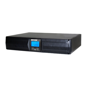
Thisdouble conversion On-Line UPS protectscomputers, servers, telecommuni-
cations,security and other electronicequipment from blackouts, brownouts,over-
voltages, and surges. This On-Line UPS converts the input AC to DC and then
back to a true sine waveAC output. The true sine wave output is regulated within
2% of the nominal output voltage. The Power Factor Correction (PFC) circuitry
correctsthe inputpower factor to within 99%of unityand blocks theload generated
harmonicdistortion from getting backon the inputACline. This On-Line UPSpro-
videsa continuous true sine wave output with zero transfer time andgreat regula-
tionto protectyour mission criticalequipment. The UPSwill quietly andconfidently
protectyour system from poweranomalies.
TheUPS will charge the batterieswhen the UPS is inthe on or off position as long
as the UPS is plugged into the wall outlet and there is an acceptableAC voltage
present(55V (load dependent)- 150VAC). Whenablackout, brownout, or an over-
voltage condition occurs while the UPS is in the On-Line mode or the Economy
mode;the UPSwill transfer tothe battery mode,the On-Batteryindicator will illumi-
nate and the audible alarm will sound once every ten-seconds indicating that the
utility power is lost or unacceptable. When the utility power returns or is at an ac-
ceptablelevel, the UPSwill automatically transferback to theOn-Line mode orthe
Economy mode and start recharging the batteries. During an extended outage
when there is approximately two-minutes of backup time remaining the audible
alarmwill sound twice every five-seconds. This Low Battery Warning is lettingthe
user know that they should save all open files and turn off their equipment. When
the batteries reach the predetermined level the UPS will automatically shutdown
protecting the batteries from over discharging. Once the utility power returns the
UPSwill automatically restartproviding safeusable power tothe connected equip-
mentand start recharging thebatteries.
The Economy mode operation: The input utility power 'bypasses' the inverter cir-
cuit and is connected directly to the output of the UPS powering the connected
equipmentwhile simultaneously charging the batteries. Whena blackout, brown-
out, or an overvoltage condition occurs the UPS will transfer to the battery mode,
theinverter will turnon poweringthe connectedequipment, theOn-Battery indicator
will illuminate and the audible alarm will sound once every ten-seconds indicating
thatthe utility power islost or unacceptable. When theutility power returns oris at
anacceptable level,the UPS will automatically transferback tothe Economy mode
andstart recharging the batteries.
