Mirage VENTUS ALPHA IVADH361A Troubleshooting guide

CONFORMS TO
UL STD. 1995
CERTIFIED TO
CSA STD. C22.2
NO. 236
& INSTALATION MANUAL
IMPORTANT NOTE:
Read this manual carefully before installing
or operating your new air conditioning
unit. Make sure to save this manual for
future reference.
Please check the applicable models, technical
data, F-GAS(if any) and manufacturer information
from the “Owner’s Manual - Product Fiche ”
in the packaging of the outdoor unit.
ALPHA INVERTER
OWNER’S MANUAL
AIR-HANDLER AIR CONDITIONERS
MODEL
IVADH361A
IVADH481A
IVADH601A
OVADH361A
OVADH481A
OVADH601A

2
Think smart. Think cool. Think Mirage.
Indoor Unit Parts And Major Functions
.............................................08
Owner’s Manual
Table of Contents
Safety Precautions
............................................................................04
Care and Maintenance...................................................................10
Troubleshooting..............................................................................12
1. Unit Parts...............................................................................................................................................................................08
2. Operating Conditions.......................................................................................................................................................08
3. Features ................................................................................................................................................................................09
4. Energy Saving Tips.............................................................................................................................................................09

3
www.hvacmirage.us
Installation Manual
........................................................................................15
....................................................................16
.....................................................................................................................................................................16
.................................................................................................................................................................16
................................................................................................................................16
..............................................................................................................23
..................................................................28
.................................................................................................................................................28
..................................................................................................................................................................29
.............................................................................................................................................................29
........................................................................31
...........................................................................................................................................31
.............................................................................................................................................31
........................................................33
..................................................................................................................................................................33
................................................................................................................................33
...................................................................................................................34
..............................................................................................37
..............................................................................................................................................................38
..................................................................................................................................................................39
........................................................................................................................................................40
.............................................................................................................................................................................43
.............................................................................................................................................................................43
...........................................................................................................................................................44
...................................................................................49
........................................................................................................................................................49
................................................................................................................................................50
..............................................................................................51
.......................................................................................................................................................................51
.............................................................................................................................................................51
Accessories
Indoor Unit Installation
1. Indoor Unit Parts
2. Safety Precautions
3. Indoor Unit Installation Instructions
4. Installation of Electric Auxiliary Heat Module
Outdoor Unit Installation
1. Select installation location
2. Install drain joint
3. Anchor outdoor unit
Drainpipe Installation
1. NOTE ON PURCHASING PIPES
2. Indoor Drainpipe Installation
Refrigerant Piping Connection
1.Safety Precautions
2.Notes On Pipe Length and Elevation
3.Connection Instructions Refrigerant Piping
Wiring
1. Outdoor Uint Wiring
2. Indoor Uint Wiring
3. Specic wiring method
4. Control Logic
5. LED DISPLAY
6. DIP Switch Denitions
Air Evacuation
1. Evacuation Instructions
2. Note on Adding Refrigerant
Test Run
1. Before Test Run
2. Test Run Instructions

4
Think smart. Think cool. Think Mirage.
Read Safety Precautions Before Operation and Installation
The seriousness of potential damage or injuries is classified as either a WARNING or CAUTION.
Incorrect installation due to ignoring instructions can cause serious damage or injury.
WARNING
This appliance can be used by children aged from 8 years and above and persons with reduced
This appliance is not intended for use by persons(including children) with reduced physical, sensory
or mental capabilities, or lack of experience and knowledge, unless they have been given supervision
or instruction concerning use of the appliance by a person responsible for their safety. Children
should be supervised to ensure that they do not play with the appliance.
physical, sensory or mental capabilities or lack of experience and knowledge if they have been given
supervision or instruction concerning use of the appliance in a safe way and understand the hazards
involved. Children shall not play with the appliance. Cleaning and user maintenance shall not be
made by children without supervision.
WARNINGS FOR PRODUCT USE
•
If an abnormal situation arises (like a burning smell), immediately turn o the unit and disconnect
the power. Call your dealer for instructions to avoid electric shock, re or injury.
•
Do not
insert fingers, rods or other objects into the air inlet or outlet. This may cause injury, since
the fan may be rotating at high speeds.
•
Do not
use flammable sprays such as hair spray, lacquer or paint near the unit. This may cause
fire or combustion.
•
Do not
operate the air conditioner in places near or around combustible gases. Emitted gas may
collect around the unit and cause explosion.
•
Do not
•
•
Do not
expose your body directly to cool air for a prolonged period of time.
•
•
•
If the air conditioner is used together with burners or other heating devices, thoroughly ventilate
the room to avoid oxygen deficiency.
Safety Precautions
Do not
allow children to play with the air conditioner. Children must be supervised around the
unit at all times.
operate your air conditioner in a wet room such as a bathroom or laundry room. Too
much exposure to water can cause electrical components to short circuit.
In certain functional environments, such as kitchens, server rooms, etc., the use of specially
designed air-conditioning units is highly recommended.
Improper installation, adjustment, alteration, service or maintenance can cause property damage,
personal injury or loss of life. Installation and service must be performed by a licensed professional
HVAC installer or equivalent, service agency, or the gas supplier.
WARNING
This symbol indicates the possibility
of personnel injury or loss of life.
CAUTION
This symbol indicates the possibility of
property damage or serious consequences.
Safety
Precautions
Page 4

5
www.hvacmirage.us
•Do not
clean the air conditioner with combustible cleaning agents. Combustible cleaning agents
can cause re or deformation.
CLEANING AND MAINTENANCE WARNINGS
•
Turn o the device and disconnect the power before cleaning. Failure to do so can cause electrical
shock.
•Do not
clean the air conditioner with excessive amounts of water.
CAUTION
•
Turn o the air conditioner and disconnect the power if you are not going to use it for a long time.
•
Turn o and unplug the unit during storms.
•
Make sure that water condensation can drain unhindered from the unit.
•Do not
operate the air conditioner with wet hands. This may cause electric shock.
•Do not
use device for any other purpose than its intended use.
•Do not
climb onto or place objects on top of the outdoor unit.
•
•
Do not
allow the air conditioner to operate for long periods of time with doors or windows open,
or if the humidity is very high.
ELECTRICAL WARNINGS
•
Only use the specified power cord. If the power cord is damaged, it must be replaced by the
manufacturer
, its service agent or similarly qualied persons in order to avoid a hazard.
•
Keep power plug clean. Remove any dust or grime that accumulates on or around the plug. Dirty
plugs can cause re or electric shock.
•
•
•
•
•
•
•
Do not
pull power cord to unplug unit. Hold the plug firmly and pull it from the outlet. Pulling
directly on the cord can damage it, which can lead to fire or electric shock.
Do not
modify the length of the power supply cord or use an extension cord to power the unit.
Do not
share the electrical outlet with other appliances. Improper or insucient power supply
can cause re or electrical shock.
If connecting power to xed wiring, an all-pole disconnection device which has at least 3mm
clearances in all poles, and have a leakage current that may exceed 10mA, the residual current
device(RCD) having a rated residual operating current not exceeding 30mA, and disconnection
must be incorporated in the xed wiring in accordance with the wiring rules.
For all electrical work, follow all local and national wiring standards, regulations, and the
Installation Manual. Connect cables tightly, and clamp them securely to prevent external forces
from damaging the terminal. Improper electrical connections can overheat and cause re, and may
also cause shock.
All electrical connections must be made according to the Electrical Connection
Diagram located on the panels of the indoor and outdoor units.
All wiring must be properly arranged to ensure that the control board cover can close properly. If
the control board cover is not closed properly, it can lead to corrosion and cause the connection
points on the terminal to heat up, catch re, or cause electrical shock.
The product must be properly grounded at the time of installation, or electrical shock may occur.
TAKE NOTE OF FUSE SPECIFICATIONS
The air conditioner’s circuit board (PCB) is designed with a fuse to provide overcurrent protection.
The specifications of the fuse are printed on the circuit board ,examples of such are T5A/250VAC and
T10A/250VAC.
As with any mechanical equipment, contact with sharp sheet metal edges can result in personal
injury. Take care while handling this equipment and wear gloves and protective clothing.
Safety
Precautions
Page 5

6
Think smart. Think cool. Think Mirage.
WARNINGS FOR PRODUCT INSTALLATION
1.
Installation must be performed by an authorized dealer or specialist. Defective installation can
Excessive Weight Hazard - Use two or more people when moving and installing the unit. Failure
to do so can result in back or other type of injury.
cause water leakage, electrical shock, or re.
2.
Installation must be performed according to the installation instructions. Improper installation
can cause water leakage, electrical shock, or re.
(In North America,installation must be performed in accordance with the requirement of NEC
and CEC by authorized personnel only.)
3.
Contact an authorized service technician for repair or maintenance of this unit. This appliance
shall be installed in accordance with national wiring regulations.
4.
Only use the included accessories, parts, and specied parts for installation. Using non-standard
parts can cause water leakage, electrical shock, re, and can cause the unit to fail.
5.
6.
Install the unit in a rm location that can support the unit’s weight. If the chosen location cannot
support the unit’s weight, or the installation is not done properly, the unit may drop and cause
serious injury and damage.
7.
8.
9.
10.
11.
12.
Do not turn on the power until all work has been completed.
When moving or relocating the air conditioner, consult experienced service technicians for
disconnection and reinstallation of the unit.
How to install the appliance to its support, please read the information for details in "indoor unit
installation" and "outdoor unit installation" sections .
For units that have an auxiliary electric heater, do not install the unit within 1 meter (3 feet) of
any combustible materials.
Do not
install the unit in a location that may be exposed to combustible gas leaks. If combustible
gas accumulates around the unit, it may cause re.
Install drainage piping according to the instructions in this manual. Improper drainage may
cause water damage to your home and property.
Note about Fluorinated Gasses(Not applicable to the unit using R290 Refrigerant)
1.
This air-conditioning unit contains fluorinated greenhouse gasses. For specic information on the
type of gas and the amount, please refer to the relevant label on the unit itself or
the
“Owner's Manual - Product Fiche ” in the packaging of the outdoor unit. (European Union
products only)
.
2.
Installation, service, maintenance and repair of this unit must be performed by a certified
technician.
Note
3.
Product uninstallation and recycling must be performed by a certified technician.
4.
For equipment that contains uorinated greenhouse gases in quantities of 5 tonnes of CO2
equivalent or more, but of less than 50 tonnes of CO2equivalent, If the system has a leak-
detection system installed, it must be checked for leaks at least every 24 months.
5.
When the unit is checked for leaks, proper record-keeping of all checks is strongly recommended.
MODEL
PRESSURE
The allowed static pressure range of the
air conditioner
on site is 0-200Pa.
Test static pressure
12-24K
25Pa 37Pa 50Pa
30-36K 48-60K
Safety
Precautions
Page 6

7
www.hvacmirage.us
European Disposal Guidelines
This appliance contains refrigerant and other potentially hazardous materials. When disposing of
this appliance, the law requires special collection and treatment. Do not dispose of this product as
household waste or unsorted municipal waste.
When disposing of this appliance, you have the following options:
• Dispose of the appliance at designated municipal electronic waste collection facility.
• When buying a new appliance, the retailer will take back the old appliance free of charge.
• The manufacturer will take back the old appliance free of charge.
• Sell the appliance to certied scrap metal dealers.
Special notice
Disposing of this appliance in the forest or other natural surroundings endangers your health and is bad
for the environment. Hazardous substances may leak into the ground water and enter the food chain.
Co rrect Disp o sal o f Th is Pro d u ct
(Wast e Elect rical & Elect ro n ic Eq u ip men t )
This marking shown on the product or its literature, indicates that waste electrical and
eletrical equipment should not be mixed with general household waste.
Safety
Precautions
Page 7

8
Think smart. Think cool. Think Mirage.
NOTE: Room relative humidity less than 80%. If the air conditioner operates in excess of this
gure, the surface of the air conditioner may attract condensation. Please sets the vertical air
ow louver to its maximum angle (vertically to the oor), and set HIGH fan mode.
Room
Temperature 17°C-32°C (62°F-90°F) 0°C-30°C
(32°F-86°F) 10°C-32°C (50°F-90°F)
Outdoor
Temperature
18°C-43°C (64°F-109°F)
-7°C-24°C
(19°F-75°F)
11°C-43°C (52°F-109°F)
-7°C-43°C (19°F-109°F)
(For models with low-temp cooling systems) 18°C-43°C (64°F-109°F)
18°C-52°C (64°F-126°F)
(For special tropical models) 18°C-52°C (64°F-126°F)
(For special tropical models)
COOL mode HEAT mode DRY mode
Room Temperature 17°C - 32°C
(62°F - 90°F)
0°C - 30°C
(32°F - 86°F)
10°C - 32°C
(50°F - 90°F)
Outdoor
Temperature
0°C - 50°C
(32°F - 122°F)
-15°C - 24°C
(5°F - 75°F)
0°C - 50°C
(32°F - 122°F)
0°C - 52°C
(32°F - 126°F)
(For special
tropical models)
0°C - 52°C
(32°F - 126°F)
(For special
tropical models)
-15°C - 50°C
(5°F - 122°F)
(For models with
low temp. cooling
systems.)
Indoor Unit Parts And Major Functions
Unit Parts Operating Conditions
Use the system under the following temperatures for safe and
eective operation. If the air conditioner is used under dierent
conditions, it may malfunction or become less ecient.
Air outlet
Air inlet
FOR OUTDOOR UNITS WITH AUXILIARY ELECTRIC HEATER
Inverter Split Type
When outside temperature is below 0°C(32°F ), we strongly
recommend keeping the unit plugged in at all time to ensure
smooth on going performance.
Fixed-speed Type
Indoor Unit
Parts And
Major Functions
Page 8

9
www.hvacmirage.us
To further optimize the performance of your unit, do the following:
•Keep doors and windows closed.
•Limit energy usage by using TIMER ON and TIMER OFF functions.
•Do not block air inlets or outlets.
•Regularly inspect and clean air lters.
Energy Saving Tips
• DO NOT
set the unit to excessive temperature levels.
• While cooling, close the curtains to avoid direct sunlight.
• Doors and windows should be kept closed to keep cool or warm air in the room.
• DO NOT
place objects near the air inlet and outlet of the unit.
• Clean the air lter every two weeks.
• Adjust louvers properly and avoid direct airflow.
Feat ures
Ref rigerant Leak Det ect ion Syst em
(some models)
In the event of a refrigerant leak, the LCD screen
will display “EL0C” and the LED indicator light will
ash.
Closing curtains during heating also
helps keep the heat in
Doors and w indow s should be kept
closed
Indoor Unit
Parts And
Major Functions
NOTE:
1. Under normal working conditions, the switch,
wind speed and temperature can not be adjusted
by remote control.
2. Requirements of wire controller:
Control AXU function for live heating
The default temperature of the rst power-on is
set to 16 degrees for refrigeration and 30 degrees
for heating. When the temperature stops, the
temperature is set at the room temperature at that
time.
Page 9

10
Think smart. Think cool. Think Mirage.
Care and Maintenance
Cleaning Your Indoor Unit
BEFORE CLEANING OR
MAINTENANCE
ALWAYS TURN OFF YOUR AIR CONDITIONER
SYSTEM AND DISCONNECT ITS POWER SUPPLY
BEFORE CLEANING OR MAINTENANCE.
CAUTION
Only use a soft, dry cloth to wipe the unit clean.
If the unit is especially dirty, you can use a cloth
soaked in warm water to wipe it clean.
•Do notuse chemicals or chemically treated
cloths to clean the unit
•Do not use benzene, paint thinner, polishing
powder or other solvents to clean the unit.
They can cause the plastic surface to crack
or deform.
•
•
Do not use water hotter than 40°C (104°F)
to clean the front panel. This can cause the
panel to deform or become discolored.
DO NOT
wash the unit under running water.
Doing so creates an electrical hazard.
Clean the unit using a damp, lint-free cloth
and neutral detergent. Dry the unit with a
dry, lint-free cloth.
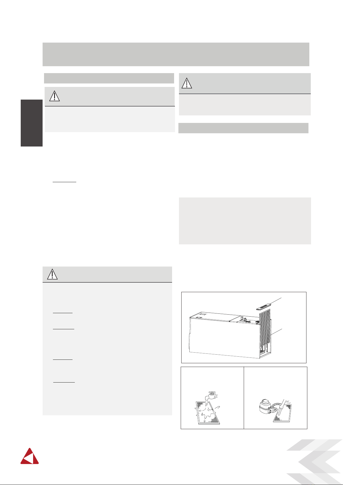
If using a vacuum cleaner,
the inlet side should face
the vacuum.
If using water, the inlet side
should face down and away
from the water stream.
2. Remove the air lter.
3. Clean the air lter by vacuuming the surface or
washing it in warm water with mild detergent.
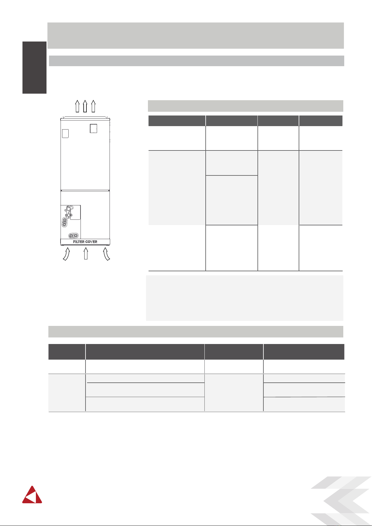
1. Remove lter cover plate.
Air lter
cover plate
Air lter
Care and
Maintenance
Page 10
• Contact an authorized service technician for
repair or maintenance. Improper repair and
maintenance may cause water leakage,
electrical shock, or re, and may void your
warranty.
•
DO NOT
substitute a blown fuse with a
higher or lower amperage rating fuse, as this
may cause circuit damage or an electrical re.
• Make sure the drain hose is set up according
to the instructions. Failure to do so could
cause leakage and result in personal property
damage, re and electric shock.
• Make sure that all wires are connected
properly. Failure to connect wires according
to instructions can result in electrical shock
or re.
How To Clean The Air Filter
The lter prevents dust and other particles from
entering the indoor unit. Dust buildup can reduce
the eciency of the air conditioner. For optimum
eciency, clean the air lter every two weeks or
more frequently if you live in a dusty area.
Replace the lter with a new one if it’s heavily
clogged and cannot be cleaned.
NOTE: In households with animals, you will have
to periodically wipe down the grille to prevent
animal hair blocking airow.
This product lter is only used for energy eciency
sampling test, the user needs to use a lter that
meets the requirements of UL900.
WA RNING: DO NOT REMOVE OR
CLEAN THE FILTER BY YOURSELF
Removing and cleaning the filter can be dangerous.
Removal and maintenance must be performed by
a certified technician.

11
www.hvacmirage.us
Maintenance –
Long Periods of Non-Use
If you plan not to use your air conditioner for an
extended period of time, do the following:
Clean all lters Turn on FAN function until
unit dries out completely
Turn o the unit and
disconnect the power
Maintenance –
Pre-Season Inspection
After long periods of non-use, or before periods
of frequent use, do the following:
Check for damaged wires Clean all lters
Check for leaks
Make sure nothing is blocking all air inlets and outlets
CAUTION
•
Before changing the lter or cleaning,
turn o the unit and disconnect its power
supply.
•
When removing lter, do not touch metal
parts in the unit. The sharp metal edges can
cut you.
•
Do not use water to clean the inside of the
indoor unit. This can destroy insulation and
cause electrical shock.
•
Do not expose lter to direct sunlight when
drying. This can shrink the lter.
CAUTION
•
Any maintenance and cleaning of outdoor
unit should be performed by an authorized
dealer or a licensed service provider.
•
Any unit repairs should be performed by an
authorized dealer or a licensed service provider.
Care and
Maintenance
Page 11

12
Think smart. Think cool. Think Mirage.
Common Issues
The following problems are not a malfunction and in most situations will not require repairs.
Troubleshooting
SAFETY PRECAUTIONS
If any of the following conditions occurs, turn o your unit immediately!
•The power cord is damaged or abnormally warm
•You smell a burning odor
•The unit emits loud or abnormal sounds
•A power fuse blows or the circuit breaker frequently trips
•Water or other objects fall into or out of the unit
DO NOT ATTEMPT TO FIX THESE YOURSELF! CONTACT AN AUTHORIZED
SERVICE PROVIDER IMMEDIATELY!
Troubleshooting
Page 12
Issue Possible Causes
Unit does not turn
on when pressing
ON/OFF button
The Unit has a 3-minute protection feature that prevents the unit from overloading.
The unit cannot be restarted within three minutes of being turned o.
The unit may change its setting to prevent frost from forming on the unit.
Once the temperature increases, the unit will start operating in the previously
selected mode again.
The set temperature has been reached, at which point the unit turns o the
compressor. The unit will continue operating when the temperature fluctuates
again.
The indoor unit
emits white mist
In humid regions, a large temperature dierence between the room’s air and the
conditioned air can cause white mist.
Both the indoor and
outdoor units emit
white mist
When the unit restarts in HEAT mode after defrosting, white mist may be emitted
due to moisture generated from the defrosting process.
The unit changes from
COOL/HEAT mode to
FAN mode
The indoor unit makes
noises A squeaking sound may occur after running the unit in HEAT mode due to expansion
and contraction of the unit’s plastic parts.
Both the indoor unit
and outdoor unit make
noises
Low hissing sound during operation: This is normal and is caused by refrigerant gas
flowing through both indoor and outdoor units.
Low hissing sound when the system starts, has just stopped running, or is defrosting:
This noise is normal and is caused by the refrigerant gas stopping or changing direction.
Squeaking sound: Normal expansion and contraction of plastic and metal parts
caused by temperature changes during operation can cause squeaking noises.
Cooling and Heating Models: If the Operation light and PRE-DEF (Pre-heating/
Defrost) indicators are lit up, the outdoor temperature is too cold and the unit’s
anti-cold wind is activated in order to defrost the unit.
In Cooling-only Models: If the “Fan Only” indicator is lit up, the outdoor
temperature is too cold and the unit’s anti-freeze protection is activated in order
to defrost the unit.
A squeaking sound is heard when the system is OFF or in COOL mode. The noise is
also heard when the drain pump (optional) is in operation.

13
www.hvacmirage.us
Troubleshooting
Issue Possible Causes
The outdoor unit
makes noises
The unit will make dierent sounds based on its current operating mode.
Dust is emitted from
either the indoor or
outdoor unit
The unit may accumulate dust during extended periods of non-use, which will be
emitted when the unit is turned on. This can be mitigated by covering the unit during
long periods of inactivity.
The unit emits a
bad odor
The unit may absorb odors from the environment (such as furniture, cooking,
cigarettes, etc.) which will be emitted during operations.
The unit’s filters have become moldy and should be cleaned.
The fan of the outdoor
unit does not operate
During operation, the fan speed is controlled to optimize product operation.
NOTE: If problem persists, contact a local dealer or your nearest customer service center. Provide
them with a detailed description of the unit malfunction as well as your model number.
Troubleshooting
When troubles occur, please check the following points before contacting a repair company.
Problem Possible Causes Solution
Poor Cooling
Performance
Temperature setting may be higher
than ambient room temperature Lower the temperature setting
The heat exchanger on the indoor
or outdoor unit is dirty
Clean the aected heat exchanger
The air lter is dirty Remove the filter and clean it according to
instructions
The air inlet or outlet of either
unit is blocked
Turn the unit o, remove the obstruction
and turn it back on
Doors and windows are open Make sure that all doors and windows are
closed while operating the unit
Excessive heat is generated
by sunlight
Close windows and curtains during periods
of high heat or bright sunshine
Too many sources of heat in the
room (people, computers,
electronics, etc.)
Reduce amount of heat sources
Low refrigerant due to leak
or long-term use
Check for leaks, re-seal if necessary and
top o refrigerant
Page 13

14
Think smart. Think cool. Think Mirage.
Troubleshooting
Problem Possible Causes Solution
The unit is not
working
Power failure Wait for the power to be restored
The power is turned o Turn on the power
The fuse is burned out Replace the fuse
The Unit’s 3-minute protection
has been activated
Wait three minutes after restarting the unit
Timer is activated Turn timer o
The unit starts and
stops frequently
There’s too much or too little
refrigerant in the system
Check for leaks and recharge the system with
refrigerant.
Incompressible gas or moisture
has entered the system.
Evacuate and recharge the system with refrigerant
The compressor is broken Replace the compressor
The voltage is too high or
too low
Install a manostat to regulate the voltage
Poor heating
performance
The outdoor temperature is
extremely low
Use auxiliary heating device
Cold air is entering through
doors and windows
Make sure that all doors and windows are closed
during use
Low refrigerant due to leak or
long-term use
Check for leaks, re-seal if necessary and top o
refrigerant
System circuit is blocked Determine which circuit is blocked and replace the
malfunctioning piece of equipment
Page 14

15
www.hvacmirage.us
Accessories
The air conditioning system comes with the following accessories. Use all of the installation parts
and accessories to install the air conditioner. Improper installation may result in water leakage,
electrical shock and re, or equipment failure.
Accessories (Packed with the indoor unit)
Accessories (Packed with the outdoor unit)
Accessori es
NOTE :
The remote control is only used to adjust the parameters.
Owner’s Manual & Installation Manual
Name Shape Quant it y
2
Remote controller
1
2
2
1
2
Battery
Transfer connector
Wired controller
Fasten belt
2
Copper nut
4
Sponge
2
Transfer connector
Name Shape Quant it y
1
1
Drain joint
Seal
Page 15

16
Think smart. Think cool. Think Mirage.
Indoor Unit Installation
Indoor Unit Parts
coil compartment (Access panel Removed)
Upow drain pan
Horizontal drain pan
Page 16
Indoor Unit
Installation
Saf et y Precautions
WARNING
•Securely install the indoor unit on a structure
that can sustain its weight. If the structure is
too weak, the unit may fall and cause personal
injury, unit and property damage, or death.
•
•
DO NOT install the indoor unit in a bathroom
or laundry room as excessive moisture can
short the unit and corrode the wiring.
CAUTION
• Install the indoor and outdoor units, cables
and wires at least 1m (3.2’) from televisions
or radios to prevent static or image distortion.
Depending on the appliances, a 1m (3.2’)
distance may not be sucient.
•If the indoor unit is installed on metal, it must
be electrically grounded.
Indoor Unit Installation Instructions
The indoor unit should be installed in a location
that meets the following requirements:
Enough room for installation and maintenance.
Enough room for the connecting pipe and
drainpipe.
The ceiling is horizontal and its structure can
sustain the weight of the indoor unit.
The air inlet and outlet are not impeded.
The airow can ll the entire room.
There is no direct radiation from heaters.
CAUTION
IM PORTANT
DO NOTinstall the unit in the following
Areas with oil drilling or fracking
Coastal areas with high salt content in the air
Areas with caustic gases in the air, such as
near hot springs
Areas with power uctuations, such as
factories
Enclosed spaces, such as cabinets
Areas with strong electromagnetic waves
Areas that store ammable materials or gas
Rooms with high humidity, such as
bathrooms or laundry rooms
locations:
Danger of explosion. Keep ammable materials
and vapors, such as gasoline, away from air
handler. Place air handler so that heating
elements are at least 18 inches (46 cm) above
the oor for a garage installation. Failure to
follow these instructions can result in death,
explosion, or re.
Please apply sealant around the places where
the wires, refrigerant pipes and condensate
pipes enter the cabinet.

17
www.hvacmirage.us
RECOM MENDED DISTA N CES BETW EEN TH E
INDOOR UNIT
The distance between the mounted indoor unit
should meet the specications illlustrated in the
following diagram.
Plenum Clearances
MINIMUM CLEARANCE
OF 25.4mm/1″ALL SIDES
FLEXIBLE
DUCT COLLAR
The outlet side pipe length is 1.5m/59’’.
1.5m/59’’
Indoor parts installation size
MODEL(Bt u/h)
Dimensions
Length of A
Length of B
12K~24K
1143
533
Length of C
Length of D
Length of E
445
400
260
30K~48K
1245
533
534
490
260
60K
1346
45 49 53
533
21 21 21
622
17-1/2 21-1/50 24-1/2
580
15-3/4 19-5/16 22-27/32
260
10-1/4 10-1/4 10-1/4
Vertical installations
Fixing instructions: When installed vertically
(upward or downward), the lower end of the air
outlet needs to be connected to the L-shaped
metal air duct and fastened by screws.
Horizontal installations
(unit: mm/inch)
A
B
C
E
D
W
D
t
MODEL(Bt u/ h)
12-24K
30-48K
W
406.4
495.3
60K 584.2
D
508
508
508
20
20
20
t
25.4
25.4
25.4
1
1
1
(unit: mm/inch)
Recommended size of lter
16
19-1/2
23
mm inch
mm
inch
mm
inch
mm
inch
mm
inch
mm
inch
mm inch mm i n ch
WARNING
IM PORTANT
Use duct tape and/or Permagum to seal closed
anyspace around the holes where the drain lines
exit thecabinet. Warm air must not be allowed
to enter throughany gaps or holes in the cabinet.
There must be an airtight seal between the
bottom of the air handler and the return air
plenum. Use berglass sealing strips, caulking,
or equivalent sealing method between the
plenum and the air handler cabinet to ensure a
tight seal. Return air must not be drawn from a
room where this air handler or any gas-fueled
appliance (i.e., water heater), or carbon
monoxide-producingdevice (i.e., wood replace)
is installed.
Page 17
Indoor Unit
Installation

18
Think smart. Think cool. Think Mirage.
Mount positions
Installat ion place
DUCT CONNECTIONS:Air supply and return
may be handled in one of several ways best suited
to the installation (See table for dimensions for
duct inlet and outlet connections). The vast majority
of problems encountered with combination cooling
systems can be linked toimproperly designed or
installed duct systems, it is therefore highly
important to the success of an installation that the
duct system be properly designed and installed.
Use exible duct collars to minimize the transmission
of vibration/noise into the conditioned space.
Where return air duct is short, or where sound is
liable to be a problem, sound absorbing glass ber
should be used inside the duct. Insulation of duct
work is a must where it runs through an uncooled
space during the cooling season. The use of a vapor
barrier is recommended to prevent absorption of
moisture from the surrounding air into the insulation.
The supply air duct should be properly sized by
use of a transition to match unit opening. All ducts
should be suspended using exible hangers and
never fastened directly to the structure. This unit
is not designed for nonducted (freeblow)
applications. Duct work should be fabricated and
installed in accordance with local and/or national
switchs.
The units can be installed in a vertical (down
and up)and Horizontal(right and left)
conguration.
NOTE: For installation, an drain pan(not
supplied) must be installed.
Vertical up installations
Horizontal installations
Vertical installations
Horizontal installations
24inch(min)
24inch(min)
IM PORTANT
A eld-fabricated secondary drain pan, with a
drain pipe to the outside of the building, is
required in all installations over a nished living
space or in any area that may be damaged by
overow from the main drain pan. In some
localities, local codes may require a secondary
drain pan for any horizontal installation.
Page 18
Indoor Unit
Installation

19
www.hvacmirage.us
T2:Evaporator central temperature sensor
T2A:Evaporator inlet temperature sensor
T2B:Evaporator outlet temperature sensor
T1:room temperature sensor
EEV: Electronic expansion valve
The unit may be installed in one of the upow,
downow, horizontal left or horizontal right
orientations .
Indication of the position of each temperature
temperature sensor of the evaporator:
12-24K model
30-48K model
60K model
downowupow
horizontal left
horizontal right
T2A
T2
EEV
T2B
T1
T2
T2A
T2B
T1
T2
T2A
T2B
T1
EEV
EEV
NOTE:
Vertical up and horizontal
left
installation does
not need to change the direction of evaporator.
Page 19
Indoor Unit
Installation

20
Think smart. Think cool. Think Mirage.
Please follow these steps to perform Vertical
up installation and Horizontal left installation:
1. Open the upper cover.
2.
Open the cover of the electronic control box.
3. Connect the wire according to the wiring
diagram.
4. Connect the pipes.
5. Install the drainage pipes.
For the Horizontal right installation and Vertical
down installation, the direction of the evaporator
should be changed . Please do it according to the
following steps:
1. Remove the cover plate of the lter ,then take
the lter o.
2. Remove the upper cover assembly.
3. Remove evaporator cover plate.
4. Remove T1、T2、T2A、T2B temperature sensor
plug、electronic expansion valve wiring
Disassemble T1、T2、T2A、T2B temperature
sensor and electronic expansion valve
R
egular installation instructions
Reversing installation instructions
T2
T2A&T2B
T1
EEV
Page 20
Indoor Unit
Installation
NOTE: T2A and T2B are only available for some
models.
This manual suits for next models
5
Table of contents
Other Mirage Air Conditioner manuals