Mirion Technologies BIODEX SOUND PRO 058-710 User manual

SOUND PRO
™
COMBINATION TABLE
This manual covers operation procedures for the following products:
058-710 Sound Pro Combination Table, 115 VAC
058-715 Sound Pro Combination Table, 230 VAC
Contact Information
Manufactured by:
Mirion Technologies (Capintec), Inc.
7 Vreeland Road, Florham Park, NJ 07932
(800) 631-3826 | (201) 825-9500 | Fax: 201-825-1336
email: FLO-TechSupport@mirion.com | www.biodex.com

TABLE OF CONTENTS
Definition of Symbols..........................................................................................................................4
Before Proceeding ...............................................................................................................................5
Important Safety Information ..............................................................................................................7
Chapter 1: Introduction ..................................................................................................................8
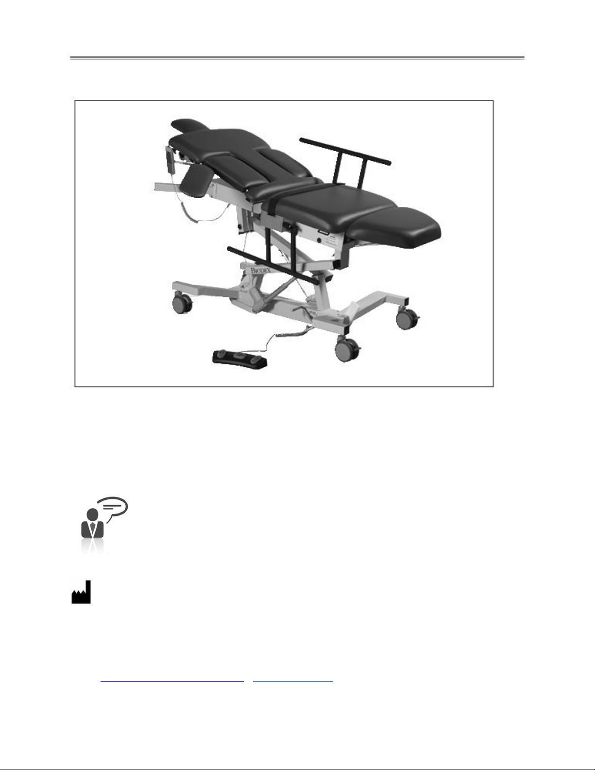
Table Parts and Adjustments ..........................................................................................................9
Chapter 2: Assembly and Table Operation ......................................................................................10
Relocating the Table.......................................................................................................................10
Height Adjustment.........................................................................................................................10
Trendelenburg Positioning .............................................................................................................10
Fowler Back Adjustment .................................................................................................................11
Leveling the Table ..........................................................................................................................11
Adjustable Sonographer Cutout Cushion.........................................................................................11
Cardiac Scanning Cutout Cushion...................................................................................................11
Installing and Using Accessories .....................................................................................................12
Foot Controller...............................................................................................................................12
Articulating Scanning Arm Board ....................................................................................................13
Side Rails .......................................................................................................................................14
Headrest ........................................................................................................................................15
Paper Dispenser .............................................................................................................................16
Retractable Stirrups........................................................................................................................17
IV Pole ...........................................................................................................................................18
Appendix A - Specifications ............................................................................................................19

4
Symbol
Definition
Carefully read these instructions prior to use
Operating Instructions
Caution
General Warning
General Mandatory Action
Dangerous Voltage
“On” Power
“Off” Power
Pinch Point
Earth (ground)
Alternating Current
Fuse
USB Connector/Cable
Non-Ionizing Electromagnetic Radiation
Waste in Electrical Equipment
Disposal Classification and Identification of Equipment
Date of Manufacture
Manufactured By
Type B Applied Part
Medical Device
Contains Lead

5
Before Proceeding
NOTE: The warnings, cautions and instructions provided in this manual must be read,
followed, and kept available for consultation at all times. Observing the information,
instructions and procedures presented throughout this manual is essential for using
this product both properly and safely.
SPECIFIC CAUTIONS
•Allow only qualified, trained personnel to operate or service this product.
•If the equipment is used in a manner other than specified in this operation manual,
the protection provided by the equipment may be impaired and results could be
compromised.
•Never leave patient unattended on table.
•When the table is used in a wet environment, it is recommended that the foot
controller be covered with a plastic bag and sealed as watertight as possible.
CAUTION: Unauthorized modifications to this product are not permitted and will void
the manufacturer’s warranty. Unauthorized modification of the product may result in
a hazard to the user and/or patient. Do not modify this equipment without
authorization from the manufacturer.
CAUTION: Before moving the table with a patient, make sure side rails are in the up
position and body straps in place to secure the patient.

6
Training
This operation manual includes assembly and operating instructions. Operating/assembly
questions can be directed to our service department during business hours.
User Profile
Patient
The product (without accessories) shall accommodate patients fitting the following profile:
Height: from infant to 74 inches (6ft - 2in)
Weight: up to 500 lbs.
Age: No limits
Operator
The operator is a trained and certified sonographer, ultrasound technician, or
ultrasound technologist.
Product Certifications and Classifications
The Sound Pro Combination Table has received the following certifications, and falls within the
following classifications:
•IEC 60601-1-2:2014+A1:2020 (ed 4.1) Medical Electrical Equipment –Part 1-2: General
requirements for basic safety and essential performance - Collateral Standard:
Electromagnetic disturbances - Requirements and tests
•IEC 60601-1:2005+A1:2012+A2:2020 Ed 3.2 Medical Electrical Equipment. Part 1. General
Requirements for Basic Safety and Performance.
•ANSI/AAMI ES60601-1:2005+A1:2012+A2:2020 Issued: 2020 Medical electrical equipment –
Part 1: General requirements for basic safety and essential performance.
•CAN/CSA-C22.2 No. 60601-1:14/A2-2022: (2022) –Medical electrical equipment –Part 1:
General requirements for basic safety and essential performance
Authorized European Community Representative:
Atlantico Systems Ltd.
34 Oldfield, Kingston, Galaway, Republic of Ireland

7
Important Safety Information
CAUTION: Federal Law restricts this device to sale by or on the order of a physician,
sonographer or other licensed professional.
Follow the unpacking and assembly instructions document.
Before using this equipment, read the entire operation manual carefully. Failure to read
the manual may result in user error or injury. Be sure to save all provided documents for
future reference.
Make certain to understand all warning and caution labels as explained in the Before
Proceeding section of this manual.
This product should be used only as specified in the operation manual.
Biodex Imaging Tables are designed for use in a patient environment.
For product specifications, refer to the Table of Contents.
This medical electrical equipment requires special precautions regarding EMC and must
be assembled and placed into service according to EMC information provided in this
manual. For electromagnetic compliance definition, refer to the Table of Contents.
Reference Cleaning and Maintenance Instructions in Table of Contents.
CAUTION: Operation for 058-710: 115 VAC, 60 Hz; 058-715 230 VAC, 50 Hz.
WARNING: Only use approved power supplies.
CAUTION: To avoid risk of electric shock, this equipment must only be connected to
supply mains with protective earth.
CAUTION: The plug is considered the method of disconnecting the product from main
power. Do not place the product in a position where the plug is not easily accessible.
CAUTION: This product is intended to remain in one location during operation. The
product is provided with wheels for relocation and should be used when performing this
operation. Once positioned, engage the central locking system lever to ensure stability.

8
1. INTRODUCTION
Intended Use
The Sound Pro Combination Table is designed to provide a safe ergonomic environment for the
sonographer and patient. The design features are intended to relieve musculoskeletal stress on
the sonographer while scanning, and to provide the utmost patient comfort.
Indications for Use
The Sound Pro Combination Table is typically used in radiology departments, diagnostic imaging
centers and private practice clinics to achieve quality images for a variety of procedures and
patient applications.
Incident Reporting
Any serious incidents occurring with the use of this device should be reported to the
manufacturer and appropriate local regulatory agency by end user, operator, or patient. Examples
of local regulatory agency are USFDA, EU competent authority, or country specific Health Agency.
End of Life
LIFETIME (END OF LIFE) The Family of Ultrasound Tables lifetime (End of Life) is considered to be
ten years after date of shipment. Service, support, and spare parts will be provided for this time.
After ten years, the system is no longer considered “state of the art” and should be replaced.
General Cleaning and Maintenance
1. As required, cleanse all exterior surfaces and tabletop pads with a mild detergent solution,
such as Parker Laboratories Protex Disinfectant or any one-step disinfectant that does not
contain bleach.
2. Keep wheel assemblies free of foreign materials and dirt accumulation.
3. Periodically inspect all welds.
4. Periodically check bolts on table, tighten if necessary.
5. Periodically inspect all strap holders. Any holder that feels loose should be removed and
reattached after adding a spot of Loctite®Threadlocker (Blue #242) to the bolt threads. This
should ensure that the bolt will not loosen again in the future.

9
Table Parts and Adjustments
Figure 1. The Sound Pro Combination Table parts and adjustment include:
Standard Parts and Adjustments:
1. Fowler Back
2. Cardiac Scanning Cutout Cushion
3. Side Rails, Folding
4. Restraining Strap
5. Extra-Wide Tabletop With 500-Lb Patient Capacity
6. Central Floor Locking System Lever
7. Foot Controller (Optional)
8.5" Locking Swivel Casters
9. Return Cardiac Scanning Cushion to Level Lever
10. Adjustable Sonographer Cutout Cushion
11. Arm Board, Vascular Scanning
12. Hand-Held Controller
13. Drop Down Leg Section
Optional:
058-737 I.V. Pole
058-738 Headrest
058-611 Dispenser, Paper, with Cutter Strap
1
2
4
5
6
7
8
9
10
12
3
11
13

10
2. ASSEMBLY AND TABLE OPERATION
Relocating The Table
CAUTION: Before moving the table with a patient, make sure side rails are in the up
position and restraining straps in place to secure the patient.
This table can be easily moved across smooth surfaces.
To move the table, release the central locking system by pressing with your foot on the short end
of the central locking lever. All four wheels release at the same time.
Once positioned, depress the end of the lever to engage the central locking system, ensuring
stability.
NOTE: In addition to the central locking system, each wheel can be locked individually by stepping
down on the individual wheel lock lever.
Height Adjustment
Table height is conveniently adjusted with the hand-held or optional foot
controller. D-ring holders are provided on the end of the straps at each side
of the table frame to hold the hand-held controller when it is not in use. The
hand-held controller can be moved to either side of the table. A power light
on the controller indicates that power from the control box is ON.
•To raise the table: press and hold down the table UP button.
•To lower the table: press and hold down the table DOWN button.
NOTE: The control box, located underneath the tabletop, is labeled with
controller specific information.
Trendelenburg Positioning
The table can provide up to + or - 15° Trendelenburg positioning by raising or lowering either
the head or foot end of the table with the hand or foot controller.
•For Trendelenburg positioning: Press and hold down the foot-end up button on the
hand-held controller. This will simultaneously raise the foot end and lower the head
end of the table. Release the button when the desired angle is achieved.
Figure 2. Hand
–held controller
activates table
positions.

11
Fowler Back Adjustment
The motorized Fowler back is infinitely adjustable to 80° via the hand-held or foot controller.
Leveling The Table
The table has a self-leveling feature which can be used when the table is in a seated position.
•To level the table, press and hold both Fowler back buttons on the hand-held control.
Adjustable Sonographer Cutout Cushion
To assure patient and sonographer comfort, the adjustable sonographer cutout cushion can be
fully lowered, or raised to either of two positions.
•To fully lower the cushion, reach under the cushion and squeeze together the two
Sonographer Cutout Cushion release handles. This will release the cushion, which can now be
lowered. To return the cushion back to the level position, squeeze the handles together and lift
up on the cushion until it is higher than level and then lower the cushion back down until it locks
in the level position.
• To raise the cushion, lift up on the cushion. There are two positions in which the raised
cushion can be set. To set the cushion in the first raised position, lift the cushion two-thirds of
the way to vertical and then allow it to slide back down slightly until you feel it lock into position.
To raise the cushion to the fully raised position, lift the cushion all the way up to vertical and
then allow it to move back slightly until it locks into place. To lower the cushion from either
raised position lift up on the sonographer cutout cushion release lever, located along the head-
end of the cushion and then lower the cushion.
Cardiac Scanning Cutout
The cardiac drop-down cushion can be released by pressing the yellow release handle which can
be found toward the lower end of the Fowler back section on each side of the table. The
cushion can be returned from either side of the table. From the right side you will find a
handle located toward the head end of the table. By pressing this handle down, the cardiac
cushion will return to level. From the left side of the table, simply push the cushion back up to
level.

12
Installing and Using Optional Accessories
NOTE: The tools needed to install all table accessories are provided with the table. These include a
7/16" wrench, a 9/16" wrench and a Phillips screwdriver.
Foot Controller (058-741)
The foot controller uses three separate rocker style pedals to control tabletop height,
Trendelenburg and Fowler positioning.
CAUTION: When the table is used in a wet environment, it is recommended that the
foot controller be covered with a plastic bag and sealed as watertight as possible.
To install the foot controller:
1. Locate the foot control port on the frame underneath the seat cushion.
2. Insert the foot controller plug into the port (labeled "foot control") so that the plug key
faces up and slides fully into the port slot. The foot controller should now be ready for use.
Using the foot controller:
To use the foot controller, simply press and hold down the appropriate rocker switch with your
foot to adjust the table as desired. Releasing the rocker switch at any time immediately stops
the motion.
Figure 3. The foot controller can be used to adjust tabletop height, Trendelenburg, and Fowler positioning.

13
Articulating Scanning Arm Board, (058-736)
The optional Articulating Scanning Arm Board is installed by inserting the arm board tube into
the receiving tube located on each side of the table below the Fowler back section. The arm
board pivot is adjustable at any point along its 130° arc. To adjust, press the yellow button on
the arm board and move to the desired location; release yellow button. (See Figures 4–7.)
To remove the arm board, press the release button beneath the receiving tube and pull to remove.
Compensator
Allen Key
Adjustment Screw Adjustment Screw
Figure 4. Figure 5. The articulating scanning arm board.
Receiving Tube Arm Board Tube
Angle Adjustment Knob
Release Button
Figure 6. Figure 7.

14
Side Rails (058-633)
The optional side rails can be installed on both sides of the table. Each rail pivots individually to
either the raised or lowered position. Two rails are supplied: one for each side of the table.
To install the side rails:
1. Using a 7/16" wrench, remove the four 1/4-20" hex head screws from under the abdominal
cushion (toward the rear of the cushion) on the side of the table to which the side rail will be
installed. Remove the strap bracket and save the screws to reinstall in step 3.
2. Position the side rail support bracket against the bottom of the cushion so the four pre-drilled
screw holes in the bracket align with the screw holes under the seat cushion.
3. Using a 7/16" wrench install the four screws removed in step 1 through the side rail support
bracket. Tighten securely.
4. Press the small piece of vinyl trim bumper onto the lower frame edge beneath the mid-point of
the seat.
5. Install the straps into the side rails strap brackets.
Using the side rails:
1. To raise either side rail, pull out the side rail pull pin and gently swing the rail upward so that it
locks fully into position.
2. To lower either side rail, pull out the side rail pull pin and, while supporting the side rail, allow it
to gently swing down and under the table until the rail locks in place.
Figure 8. Installing the side rails.

15
Headrest (058-738)
The optional headrest is removable and adjustable. To install the headrest, simply slide it into
the receiving tube at the head end of the table until it clicks into place.
Figure 9. The optional headrest.
Figure 10. Headrest adjustments.
Push to adjust angle.
Push to release.

16
Paper Dispenser (058-611)
Manufactured to accommodate a roll of hygienic table paper (sold separately,) the paper
dispenser is mounted to the head end of the table.
Installing the paper dispenser:
1. Raise the Fowler back section of the table completely.
2. Using a 7/16" wrench, remove the two 1/4-20" hex head screws from under one side of
the head end of the Fowler back cushion.
3. Position the appropriate paper dispenser mounting bracket on the bottom of the Fowler
back cushion as shown below. Ensure the pre-drilled screw holes align with the screw hole
from step 2.
4. Using a 7/16" wrench, install the two 1/4-20" hex head screws removed in step 2
through the dispenser mounting bracket and tighten to secure the paper dispenser bracket
in place.
5. Repeat steps 1 - 4 for the opposite side.
6. Place a role of paper on the paper dispenser rod and install the rod between the
brackets.
Press in on either spring-loaded end of the paper dispenser bar in order to slide it into the
brackets.
7. Pull the paper over the cushions.
8. Pull unused paper through the cutter strap which mounts at the foot end of the table.
9. After use, cut the paper and dispose of used portions.
Figure 11. Using a 7/16" wrench, install the two1/4-20"
hex head screws removed in step 1 through the dispenser
mounting bracket and tighten to secure the paper
dispenser bracket in place. Repeat steps 1 - 4 for the
opposite side.
Figure 12. Place a roll of paper on the paper dispenser rod
and install the rod between the brackets. Press in on either
spring-loaded end of the paper dispenser bar in order to
slide it into the brackets.
Mounting Bracket
Mounting Bracket

17
Retractable Stirrups (058-652)
A set of sturdy retractable Stirrups can be neatly concealed in the table frame beneath the
abdominal (seat) cushion. The two stirrups are interchangeable and can be mounted in either
stirrup housing.
To access the stirrups:
1. Lower the drop-down leg section.
2. Lift up slightly on the stirrups and then slide them fully out from the table frame. The stirrups
can be used in various positions and do not have to be fully extended for use. The stirrups also
pivot from side to side.
3. Unfold the stirrups’heel cups for use.
To retract the stirrups:
1. Fold the stirrups’heel cups.
2. Lift up slightly on the stirrups and slide them fully back into the table frame.
NOTE: The stirrups must be fully retracted before raising the drop-down leg section to prevent
the stirrups from damaging the cushion.
Figures 13 and 14. Retractable Stirrups.

18
I.V. Pole (058-737)
The I.V. pole must be installed on the patient's right side of the table.
Installing the I.V. pole:
1. Using a 7/16" wrench, remove the two 1/4-20" hex head screws from the end of the
tabletop frame on the side of the table to which the I.V. pole will be installed.
2. Position the I.V. pole support bracket against the side frame so the two pre-drilled screw
holes in the bracket align with the screw holes on the tabletop frame. The I.V. pole should
face up and toward the head end of the table.
3. Using a 7/16" wrench, install the two screws removed in step 1 through the I.V. pole
mounting bracket. Tighten the screws to secure.
4. Insert the I.V. pole into the I.V. pole mounting bracket. Ensure that the I.V. pole passes
through both the top and bottom holes in the mounting bracket to ensure I.V. pole stability.
Figure 15. Installing the I.V. pole.

19
APPENDIX A - SPECIFICATIONS
Dimensions:
Overall: 71" l x 30" w (180.3 x 76.2 cm); 35" w (88.9 cm) with optional side rails
Cardiac Scanning Cutout: 9.5 w x 15.75 l (24.1 x 40 cm) Drop-down cushion releases from
either side of the table.
Sonographer Cutout: 8" w x 14.75" l (20.3 x 37.4 cm) Adjustable sonographer cushion
drops down or folds up for maximum access to the patient.
Drop-Down Leg Section: 12.6" l (32 cm)
Motions:
Height Adjustable: 23" to 39" (58.4 to 99 cm)
Trendelenburg: 0° to ±15°
Fowler Back: 0° to 80° infinitely adjustable
Controls:
Hand Control: Activates height, Trendelenburg motions, Fowler positioning and auto level
motions.
Foot Control: Activates height, Trendelenburg motions and Fowler positioning.
Wheels: 5" (12.7 cm) individual locking swivel casters; central floor-locking system
Tabletop: Three primary sections: torso section features sonographer and patient cutouts with
Fowler positioning; center section remains fixed and leg section drops down to 40° and 80° for
stirrup access
Drop-Down Cardiac Scanning Cushion: Release from either side of the table
Adjustable Sonographer Cushion: Drops down or folds up for maximum access to the patient.
Mattress: Torso section 2" (5 cm) thick, center and leg sections 3" (8 cm) thick; Naugahyde®,
antimicrobial mattress cover with advanced BeautyGard®provides protection against bacteria
Upholstery Color: Graphite
Patient Restraints:
One body strap
Finish: Powder coat
Patient Capacity: 500 lb. (227 kg); weight tested to four times the patient load rating.
Weight: 350 lb. (159 kg)
Power: 115 VAC OR 230 VAC

7 Vreeland Road, Florham Park, NJ 07932
(800) 631-3826 | (201) 825-9500 | www.biodex.com
This manual suits for next models
1
Table of contents
Other Mirion Technologies Medical Equipment manuals