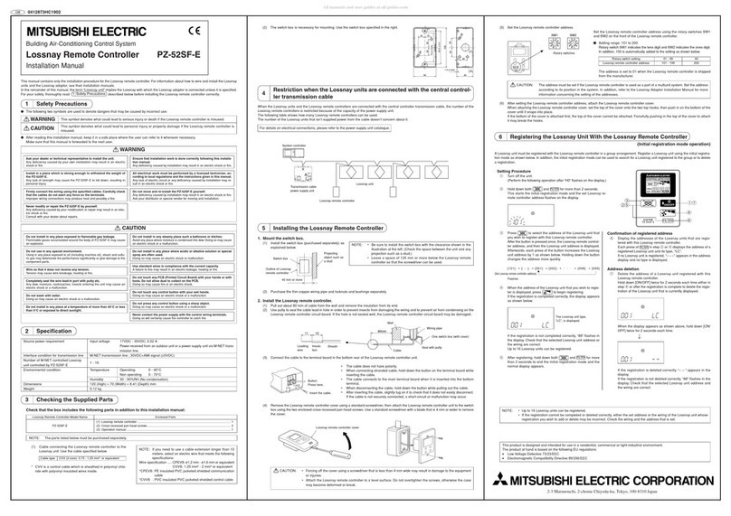
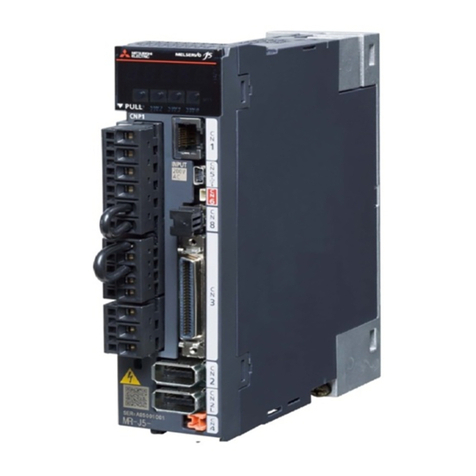
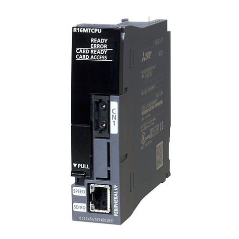
12 2 TRANSITION FROM LE-40MTA, B(-E) TO LE7-40GU-L
2.2 Comparison of I/O Terminal Blocks
Terminal specifications
Since the terminal type changes from a screw type terminal to a spring clamp type terminal, stranded wires and bar type crimp
terminals are used for wiring. Therefore, when using a round terminal and Y terminal, terminal processing of the wiring is
necessary.
Tension
detector
Input GRL Left Tension detector input
Connect the lead wires GR=green (blue) and
WH=white.
Use the parameter to specify the number of
detectors to be used: one or two.
The connection varies depending on the
compression/tensile load. When one detector is
used, it is necessary to make a short circuit
between GRL and WHL.
GRL Left Tension detector input
• Input range switchable
(1) -150 to +150 mV DC (LX tension detector)
resolution: Approx. 7.90 V
(2) -15 to -15 mV DC (strain gauge) resolution:
Approx. 0.790 V
When only the detector on one side is used, it is
necessary to make a short circuit between GR and
WH on the other side.
The compression/tensile load is determined
automatically.
WHL WHL
GRR Right GRR Right
WHR WHR
SG For shield connection SLD For shield connection
Analog Input AI1 External tension setting: 0 to full scale tension at 0
to 5 V DC
Internal resistance: 100 k
Recommended potentiometer (control): 5 V 10 k
AI1 Selection from tension setting, stall, taper ratio,
new-reel preset, manual, tension input, and reel
• Input range switchable
(1) 0 to 5 V DC resolution: Approx. 193 V
(2) 0 to 10 V DC resolution: Approx. 193 V
• Input resistance 38 k
AI2 Selection from reel diameter, stall, new-reel taper
ratio setting, and external tension
Recommended potentiometer (control) 5 V 10 k
AI2
AI3 AI3
AIC Analog input common AIC Analog input common
Output TMO Output for tension monitor
Filter adjustable by parameter
0 to 5 V DC
Load resistance: 1 kor more
AO1 Selection from tension monitor, reel diameter
monitor, tension setting monitor, A-reel shaft
rotation speed output, and B-reel shaft rotation
speed output selection
• Output range switchable
(1) 0 to 5 V DC resolution: Approx. 358 V
(2) 0 to 10 V DC resolution: Approx. 358 V
• Load resistance: 1 kor more
AO2
AOC Analog output common AOC Analog output common
Contact Input MC1 Operation/stop: ON=automatic operation,
OFF=stop
DI1 Selection from operation/stop, control output OFF/
ON, stall memory, inching ON/OFF, constant
tension ON/OFF, gain 1 ON/OFF, gain 2 ON/OFF,
auto/manual, reel change ON/OFF, cut torque ON/
OFF, and alarm reset ON/OFF
• Input signal voltage 24 to 28.8 V DC
• ON current about 5 mA
• Sink/source input
MC2 Reel change signal: OFF=A reel, ON=B reel DI2
MC3 Gain 1 operation: Gain 1 enabled during ON DI3
MC4 Stall memory reset: About 0.5 second one-shot
input
DI4
MC5 Assigned by parameter settings and used.
• Gain 2: Gain 2 enabled during ON
• Inching: Output lower limit restriction, stall
memory update stop
• OUT remote: Control output ON during ON
• Cut torque: During ON, output lower limit
restriction, cutter
DI5
MC6 DI6
MCC Contact input common 0V In sink input mode, 0 V becomes contact input
common.
S/S In sink input mode, this terminal connects to 24 V.
Output ZT • Zero tension detection output: Set value 0 to
1999 N (199.910 N)
• Output ON at tension below the set value:
Always OFF when the set value is 0 (however,
the output is ON regardless of the set value and
tension when the watchdog timer is operating).
• Relay output (250 V AC 0.5 A or 30 V DC 0.5 A)
DO1 Selection from no function, tension lower limit
detection, tension upper limit detection, tension out
of range detection, and alarm occurrence detection
• Open collector output (30 V DC, 0.1 A or less)
DO2
ZT DOC Contact output common
Item name LE-40MTA, B(-E) LE7-40GU-L
Function Terminal Specifications Terminal Specifications