6
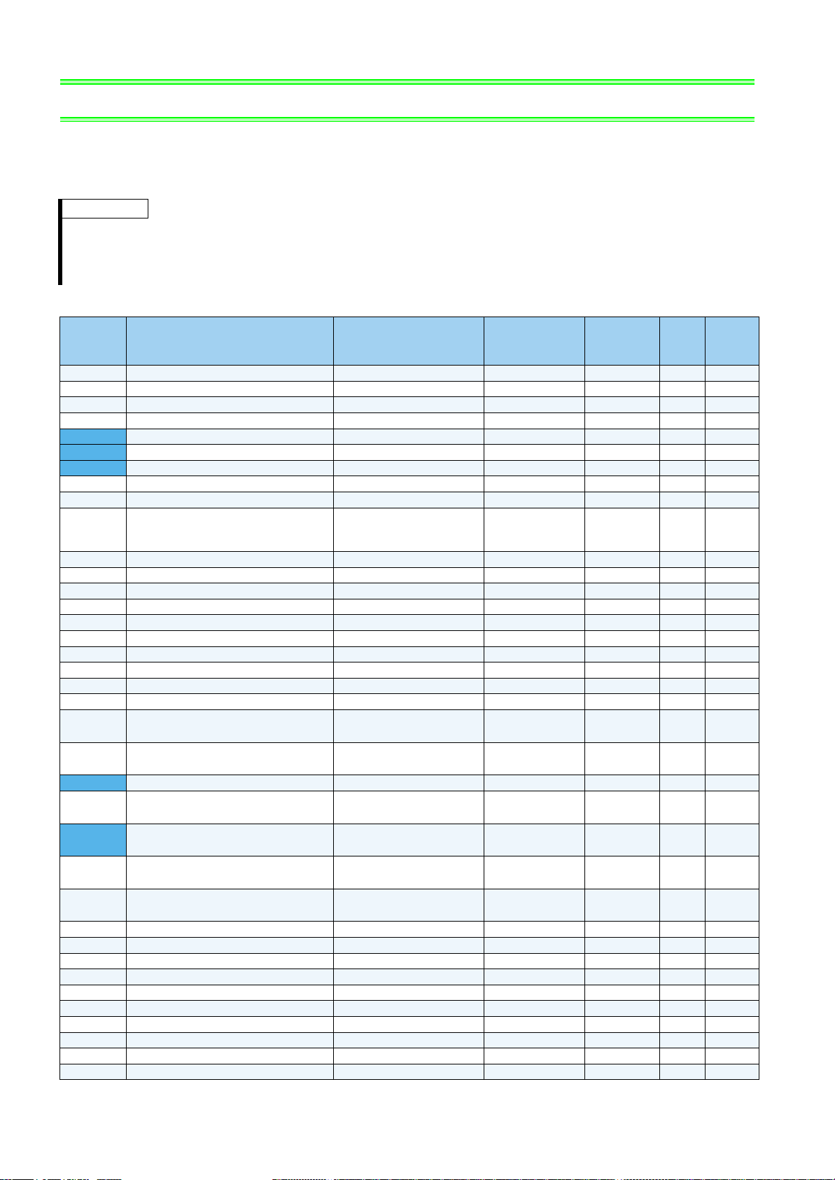
PARAMETER LIST
185 JOG terminal function selection
0 to 20, 22 to 28, 30,
32 to 35, 42 to 44, 62,
64 to 71, 74, 76, 83, 9999
1 5 16
186 CS terminal function selection 1 6 16
187 MRS terminal function selection 124 16
188 STOP terminal function selection 1 25 16
189 RES terminal function selection 162 16
190 RUN terminal function selection 0 to 8, 10 to 16, 25, 26,
30 to 35, 39, 41 to 47,
50 to 54, 64, 70, 85, 90, 91,
93 to 99, 100 to 108,
110 to 116, 125, 126,
130 to 135, 139, 141 to 147,
150 to 154, 164, 170, 185,
190, 191, 193 to 199, 9999
1017
191 SU terminal function selection 1 1 17
192 IPF terminal function selection 1 2 17
193 OL terminal function selection 1 3 17
194 FU terminal function selection 1 4 17
195 ABC1 terminal function selection
0 to 8, 10 to 16, 25, 26,
30 to 35, 39, 41 to 47,
50 to 54, 64, 70, 85, 90, 91,
94 to 99, 100 to 108,
110 to 116, 125, 126,
130 to 135, 139, 141 to 147,
150 to 154, 164, 170, 185,
190, 191, 194 to 199, 9999
199 17
196 ABC2 terminal function selection 1 9999 17
232 to 239 Multi-speed setting (8 speed to 15
speed) 0 to 400Hz, 9999 0.01Hz 9999 —
240 Soft-PWM operation selection 0, 1 1 1 —
241 Analog input display unit switchover 0, 1 1 0 —
242 Terminal 1 added compensation
amount (terminal 2) 0 to 100% 0.1% 100% —
243 Terminal 1 added compensation
amount (terminal 4) 0 to 100% 0.1% 75% —
244 Cooling fan operation selection 0, 1 1 1 —
245 Rated slip 0 to 50%, 9999 0.01% 9999 —
246 Slip compensation time constant 0.01 to 10s 0.01s 0.5s —
247 Constant-power range slip
compensation selection 0, 9999 19999 —
251 Output phase loss protection selection 0, 1 1 1 —
252 Override bias 0 to 1000% 0.1% 50% 44
253 Override gain 0 to 1000% 0.1% 150% 44
255 Life alarm status display (0 to 15) 1 0 —
256 Inrush current limit circuit life display (0 to 100%) 1% 100% —
257 Control circuit capacitor life display (0 to 100%) 1% 100% —
258 Main circuit capacitor life display (0 to 100%) 1% 100% —
259 Main circuit capacitor life measuring 0, 1 1 0 —
261 Power failure stop selection 0, 1, 2, 11, 12 1 0 —
262 Subtracted frequency at deceleration
start 0 to 20Hz 0.01Hz 3Hz —
263 Subtraction starting frequency 0 to 120Hz, 9999 0.01Hz 60Hz —
264 Power-failure deceleration time 1 0 to 3600/ 360s 0.1/0.01s 5s —
265 Power-failure deceleration time 2 0 to 3600/ 360s, 9999 0.1/0.01s 9999 —
266 Power failure deceleration time
switchover frequency 0 to 400Hz 0.01Hz 60Hz —
267 Terminal 4 input selection 0, 1, 2 1 0 —
268 Monitor decimal digits selection 0, 1, 9999 19999 —
269 Parameter for manufacturer setting. Do not set.
270 Dancer position A 400.1% to 600% 0.1% 600% 30
271 Dancer position B 400% to 599.9% 0.1% 400% 30
272 Dancer position C1 400.1% to 599.9%, 9999 0.1% 9999 30
273 Dancer position C2 400.1% to 599.9%, 9999 0.1% 9999 30
274 PID position gain A 0.1 to 1000%, 9999 0.1% 9999 30
275 PID position gain B 0.1 to 1000%, 9999 0.1% 9999 30
Parameter
Name Setting Range
Minimum
Setting
Increments
Initial
Value
Refer
to
Page
Customer
Setting


 User manual")
0.4K User manual")