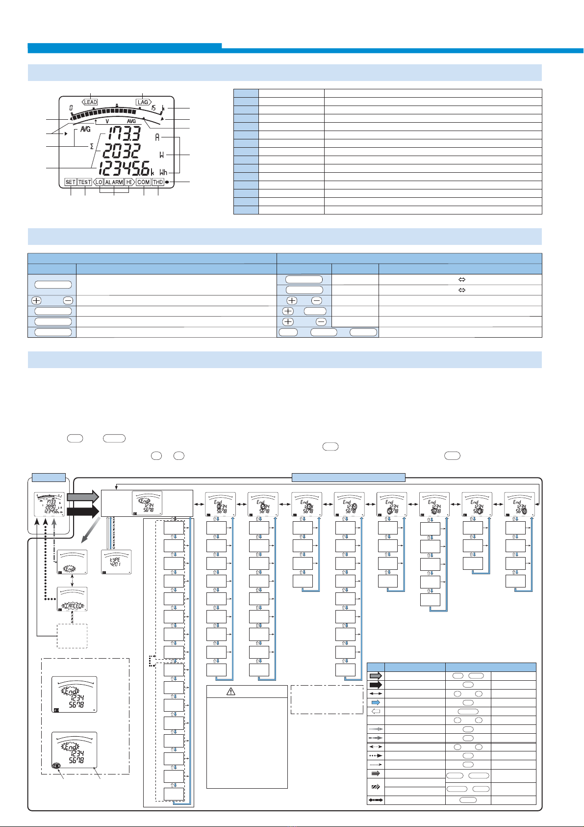
Functions of Buttons
Settings
LEAD status
LAG status
Scale of the bar graph
Outside range
Alarm indicator
Bar graph status
Phase status
Unit
Metering status
Harmonics
Communication status
Alarm status
Test status
Setup status
Digital
They show direction of Power Factor or Reactive Power on bar graph.
They show the type of counting of Reactive Energy on Reactive Energy Display.
They show the scales of the bar graph.
Measurement value is outside range of scale of the bar graph.
It shows the setting value of the upper limit or lower limit.
They show the item expressed with the bar graph.
They show the phase for each of the digital displays.
They show the unit for each of the digital displays.
When it is blinking, the instrument is counting active energy.
It means that the digital displays are harmonics values.
It shows that the instrument is equipped with a communication function.
They show that the upper limit value or lower limit value was exceeded.
It shows that the output of the option module is tested.
It appears at Set-up mode.
The measured value is displayed in a digital number.
1
2
3
4
5
6
7
8
9
10
11
12
13
14
15
snoitcnuFButtonssnoitcnuF Operations
Special functionsBasic functions
Buttons
SET
or
MAX/MIN
PHASE
DISPLAY
Set up setting items such as primary voltage or primary
current, and choose and indicate setting items.
Change settings and bar graph display.
Change display from Max/Min to instantaneous value.
Change phases.
Change display.
Press for 2 sec.
Press for 2 sec.
Press for 2 sec.
Press for 2 sec.
Press for 1 sec.
DISPLAY
PHASE
&
&
RESET
or
Manual display change Cyclic display change
Manual phase change Cyclic phase change
Zoom display of Wh, varh values (last 3 digits)
Reset all the Max/Min values.
Fast forward or fast return values when setting.
Reset Wh, varh values to zero by holding down the buttons for 2 sec.
SET &
RESET
&
PHASE
For correct measurement, it is necessary to set the primary voltage and the primary current, etc. in the Set-up mode. It can set necessary items,
after it shifts from the Operation mode to Set-up mode. Items not set are on the initial setting. In case of regular use, it can be used by setting only
the Set-up menu 1(basic set-up).
In case of using the communication function, set Set-up menu 2. Refer to the next page or later for the set-up items.
Note: The above display is an example for explanation.
● Set-up Diagram
➀
Press SET and RESET simultaneously for 2 seconds to get in the
Set-up mode.
➁
Select a Set-up menu number by or .
➂
Change the contents in each Set-up menu. (Refer to pages 7-14.)
➃After completion of set-up, select ‘End’ in the Set-up menu and press
.
➄When the End display appears, press once again.
+–
SET
SET
Shift from the operation mode to
the set-up mode.
Press them simultaneously
for 2 seconds.
Press them
simultaneously for 1
second.
Press them
simultaneously for 1
second.
Shift from the operation mode to
the set value confirmation mode.
Select the menu number to set or
“End”.
Get into each setting screen. Shift
to the next setting item.
Go back to the previous setting
item.
Memorize the setting contents, and
go back to the operation mode.
Skip remaining setting items
during setting.
Shift from the set-up mode to
simplified set-up menu.
Change the page of the simplified
set-up menu.
Phase
wire
Display
pattern
Using VT/
direct input
Direct
voltage
Secondary
voltage
Primary
voltage
Secondary
current
Primary
current
Time constant
for current
demand
Phase
wire
Display
pattern
Using VT/
direct input
Direct
voltage
Secondary
voltage
Primary
voltage
Primary
current
Time constant
for current
demand
CC-Link
station
number
Communication
method
ModBus
address
ModBus
baud rates
ModBus
parity
ModBus
stop bit
CC-Link
baud rates
Communication
module reset
Expanded
counting
Harmonics
Digital
input/output
Back light
ON/OFF
Current
display
digit
Voltage
display
digit
Active
power
display digit
Reactive
power
display digit
Apparent
power
display digit
Communication
method
ModBus
address
ModBus
baud rates
ModBus
parity
ModBus
stop bit
CC-Link
baud rates
Communication
module reset
Digital input
reset
Current
maximum
scale
Active power
maximum
scale
Reactive power
maximum
scale
Power
factor scale
Analog
output 1
Analog
output 2
Analog
output 3
Analog
output 4
Analog
output limit
Alarm
item
Alarm
value
Alarm
delay time
Operation mode
Measurement display
Action
Select a set value.
Shift to the End screen.
Select “CANCEL”.
Cancel the setting.
Display the type of option unit.
Initializing of instrument
Key operation
Press it for 2 seconds.
Press it several times.
Press it.
Press it.
Press it several times.
Press it.
Press it.
Press it.
Press it.
Press it for 1 second.
Press it.
or
or
or
Omitted
in figure
Arrow in
figure
+
+
+
Set-up mode or set value confirmation mode
Set-up menu “End”
End display
Type of option
display
P-1
P-2
CANCEL display
Example of
set-up mode
Set-up menu 1 Set-up menu 2 Set-up menu 3 Set-up menu 4
Analog
output 1 Adj.
Analog
output 2 Adj.
Analog
output 3 Adj.
Analog
output 4 Adj.
Pulse
output 1
Pulse
width
Set-up menu 5 Set-up menu 6 Set-up menu 8Set-up menu 7
Simplified set-up menu
blink extinction
Pulse
output 2
CC-Link
station
number
Alarm
cancel
method
+–
+–
SET
SET
SET
SET
SET
SET
SET
RESET
PHASE DISPLAY
DISPLAY
PHASE
PHASE
MAX/MIN
+–
Initializing
process
Shift
automatically
(Example)
Example of set value
confirmation mode
14
12
13 12 11 10
9
8
5
4
3
4
6
7
15
✽ This figure writes all set menus.
There is a menu not displayed
by the presence of the setting
condition and the option.
CAUTION
1. Make sure to set for Direct
voltage, Secondary voltage,
Primary voltage, Secondary
current, Primary current.
(Or check the set-up contents.)
A correct measurement cannot
be done if the set-up contents
are wrong.
2. Set for the other set-up contents
when it is necessary.
When it is not done, it operates
with the initial contents.
Functions of LCD
Functions
● How to access Set-up
6