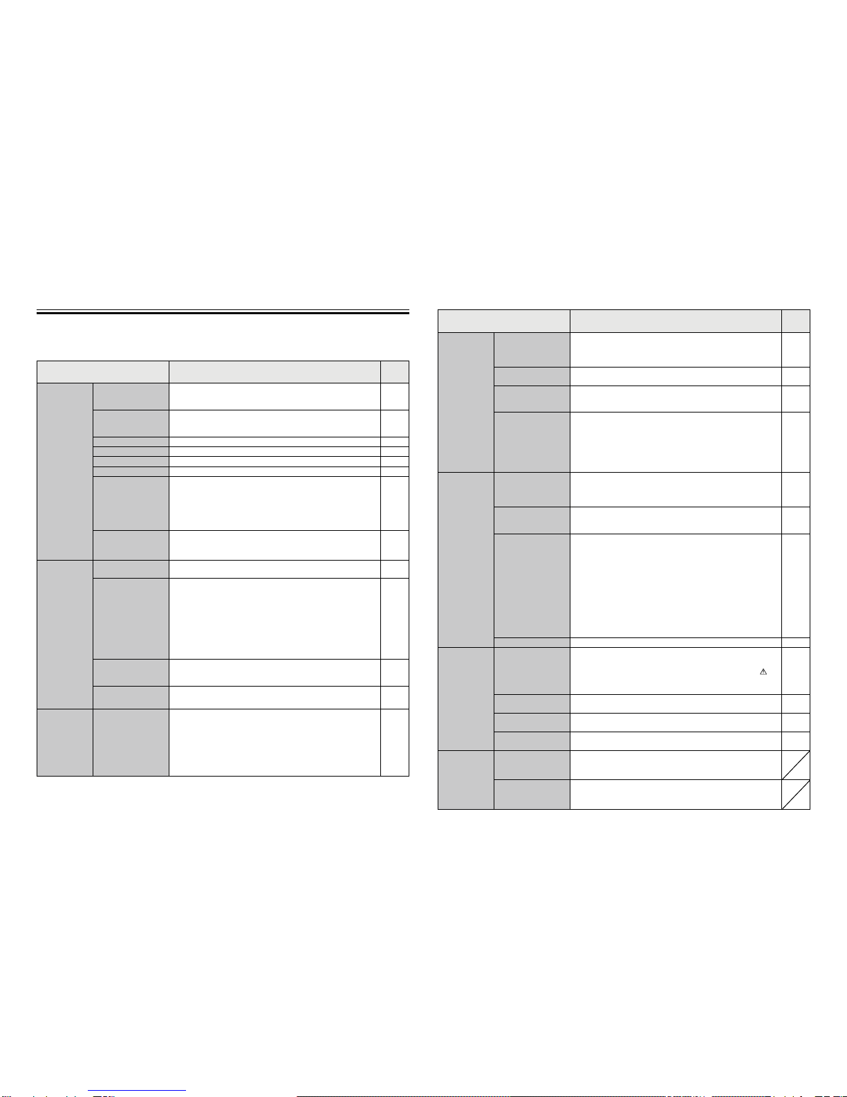
Function List
The table below summarizes the functions that are available on the AT-50A.
Refer to the pages listed for details.
Function Description Page
Unit Operation
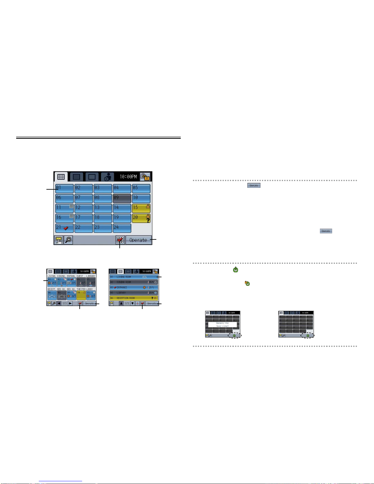
ON/OFF Operation Switches the ON/OFF operation of the units such as air conditioning
units. The LED on the Collective ON/OFF button will light up when one
or more units are in operation and off when all units are stopped. 18
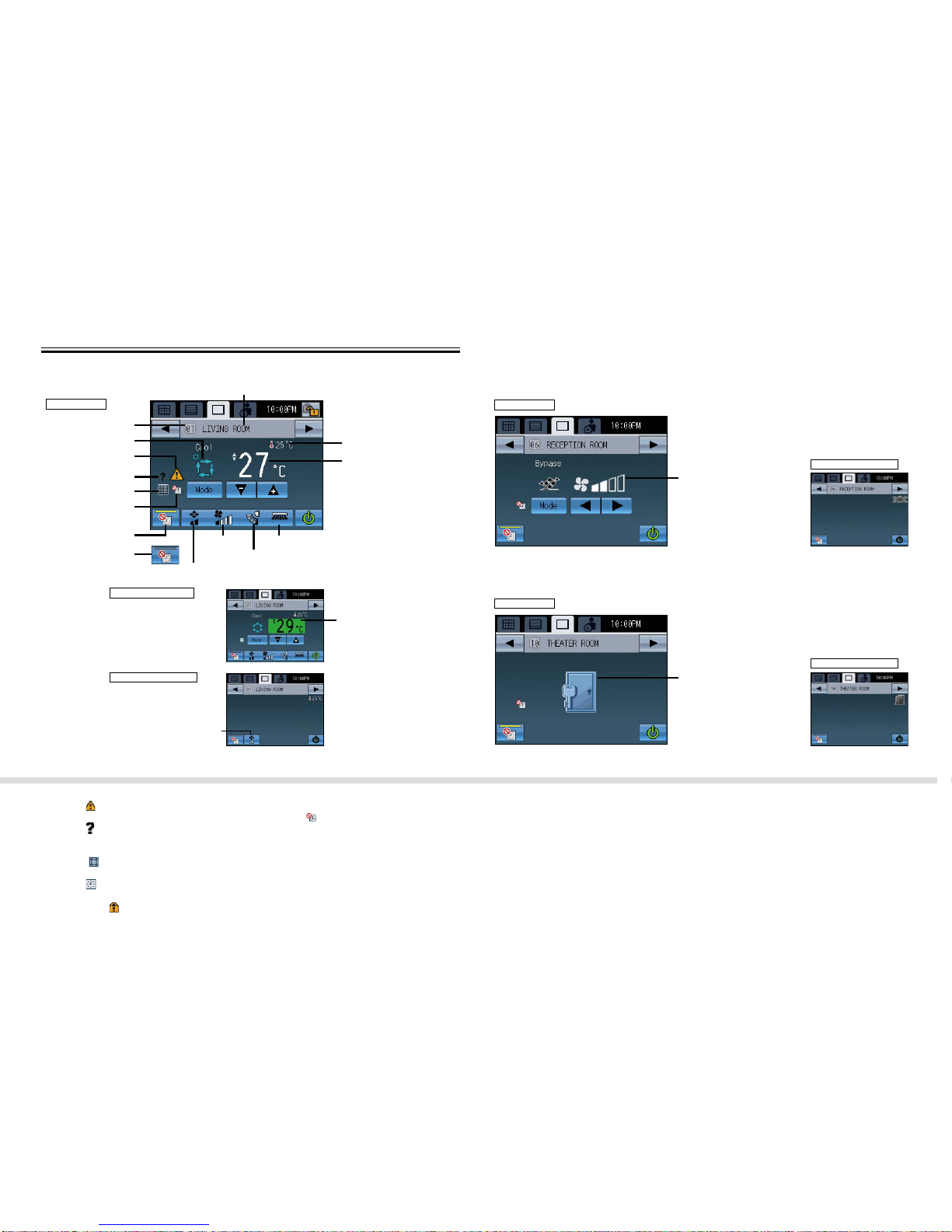
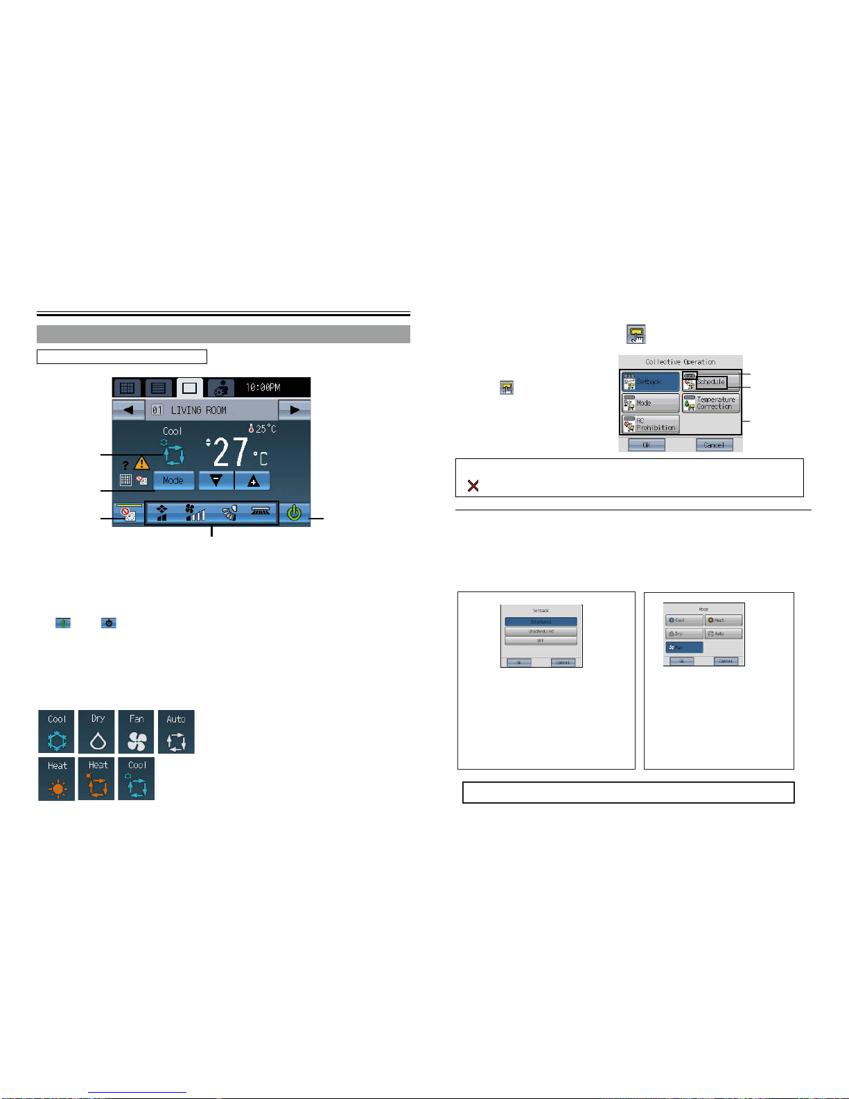
Mode Switches the mode “Cooling/Dry/Fan/Auto/Heating” for each group or all
groups. (Switches the mode “Bypass/Heat recovery/ Auto” for LOSSNAY
groups.) 18
Set Temperature Sets the set temperature for each group or all groups. 20
Fan Speed Adjusts the fan speed for each group or all groups. 21
Air Direction Adjusts the air direction for each group or all groups. 21
Louver Enables/disables the louver for each group or all groups. 21
ON/OFF Operation
for Interlocked
Ventilation
The ON/OFF operation of the interlocked ventilation unit is interlocked
with the ON/OFF operation of the air conditioning unit. The interlocked
ventilation units can be independently operated for ON (High/Low)/ OFF
for each group or all groups. (When the ventilation unit is interlocked
with the air conditioning unit, the ventilation mode cannot be used.)
21
Collective Operation The following functions can be collectively executed on multiple groups:
Setback, Schedule, Mode, Temperature Correction, RC Prohibition. 19
38
Time and
Schedule
Date and Time Sets the date, time, and display formats. The current time will appear at
the top right corner of the HOME screen. 27
Weekly/1-day
schedule
• Allows the user to set the Weekly schedule for each group.
• Maximum of 16 events can be scheduled for each day.
• The types of actions that can be scheduled are as follows: ON/OFF,
Mode, Set Temperature, Fan Speed, Air Direction, and Remote
Controller Operation Prohibition.
• Maximum of 12 patterns can be congured for the Weekly schedule,
and 5 for 1-day schedule.
• Two types of weekly schedule (Summer/Winter) can be set.
• 1-day schedule overrides the Weekly schedule.
27
Setback Control This function helps keep the indoor temperature in the
temperature range while the units are stopped and during the
time this function is effective. 35
Disabling scheduled
operation Scheduled operation can be temporarily disabled.
This setting must be set to OFF to run scheduled operation. 22
System
Management System-Changeover
Automatically switches the entire system (all indoor units that are
connected to the same outdoor units) to Cooling or Heating by
periodically monitoring the room temperature and the preset temperature
of each group and determining the best operation mode.
• The System-Changeover function is not available for the following
types of products: Simultaneous Cooling/Heating units (with automatic
mode change function), Mr. SLIM®, LOSSNAY, and DIDO controller.
59
*1: Available functions vary depending on the unit type. Only the functions that are supported by the connected units can
be controlled from the AT-50A.
*1
Function Description Page
Restriction
Settings
Lock Buttons
Locks the following buttons: Collective ON/OFF, F1, F2, and Main
Menu.
Locks the following functions: ON/OFF, Mode, Set Temp, Fan
Speed, and Schedule ON/OFF.
11
23
42
Set Temperature
Range Limit Limits the available temperature range for the local remote
controllers (each group or all groups). 44
Prohibit Remote
Controller
Locks the following buttons on the local remote controllers: ON/
OFF, Mode, Set Temperature, and Filter Reset buttons (collectively
or by group) 46
Operation Mode
Selection Limit
When set as the main controller, operation of the following modes
with the local remote controllers can be prohibited.
When cooling is prohibited: Cooling, dry, automatic cannot be
chosen.
When heating is prohibited: Heating, automatic cannot be chosen.
When cooling/heating is prohibited: Cooling, dry, heating, automatic
cannot be chosen.
48
Basic Settings
Display Format
Selects the display formats for the following items: Display
language, temperature unit, room temperature, display or non-
display of Cooling/Heating mode icons (during Auto mode),
backlight timer, and group names.
50
Function Key Setting The F1 button and the F2 button can be set as a run button of the
following collective operation: Setback, Schedule, Operation Mode,
Temperature Correction, Remote Controller Prohibition. 54
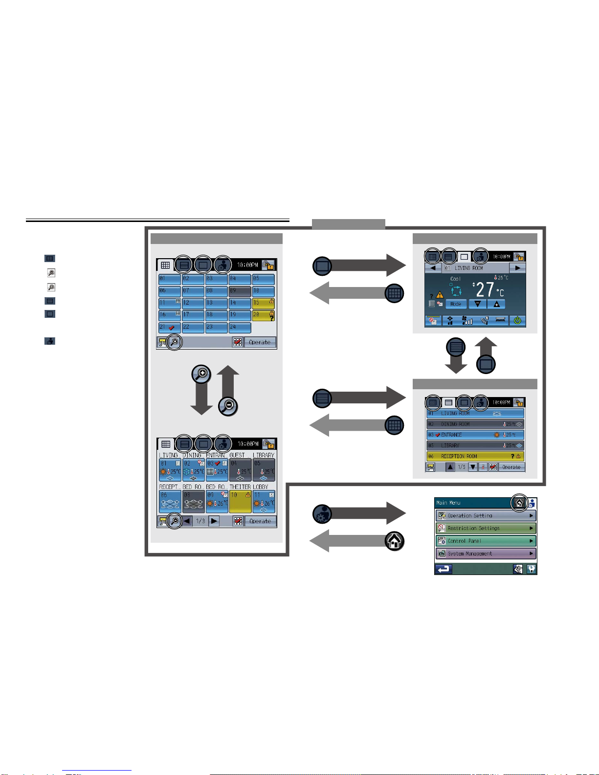
HOME screen
Operation Mode
Setting
When the Group icon is touched, the action differs depending on
the operation mode. Default is set to the operation mode 2.
Operation mode 1: Turns ON/OFF the units in the group whose
Group icon is touched.
Operation mode 2: Displays the check mark when Group icon is
touched. Touch the Group icons of the groups
to be operated, and then touch the “OPERATE”
button to move to the Group screen. Multiple
groups can be selected. Use this mode when
operating the multiple groups collectively.
Operation mode 3: Directly moves to the Group screen of the
group whose Group icon is touched.
41
Volume Control Sets the sound volume and screen brightness. 55
Maintenance
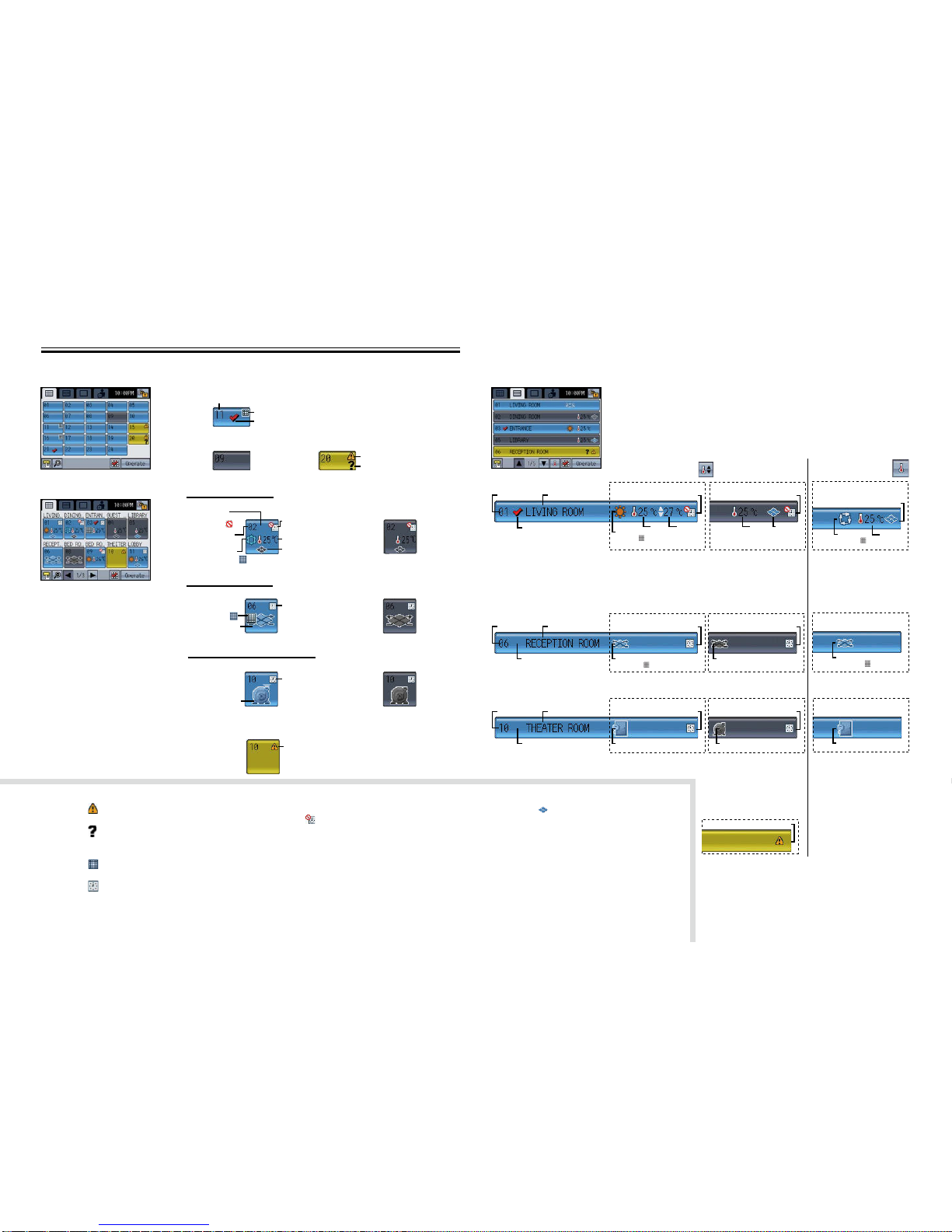
Error
If an error occurs on the AT-50Acontroller or the units and
controllers it controls, the LED on the Collective ON/OFF button
will blink. If an error occurs on the indoor or LOSSNAY units, will
appear on the corresponding group icon on the HOME screen. The
error code can be veried and reset on the Status List screen.
57
Filter sign Filter Icon will appear on the HOME screen when the lter is due
for cleaning. The icon can be removed from the Status List screen. 57
Touch Panel
Cleaning Mode Disables the touch panel to allow the user to clean the panel. 61
Touch Panel
Calibration Mode Calibrates the touch panel if the touch panel does not respond
correctly when touched. 56
Miscellaneous
External input
Receives input signals from external devices and start/stop all
groups of units or permit/prohibit operations from the local remote
controllers. Requires cable connections.
External output
Outputs the operation status of the units (ON/OFF) or error signals
to external devices collectively, using contact signals. Requires
cable connections.
*1
*1
*1
*1
*1