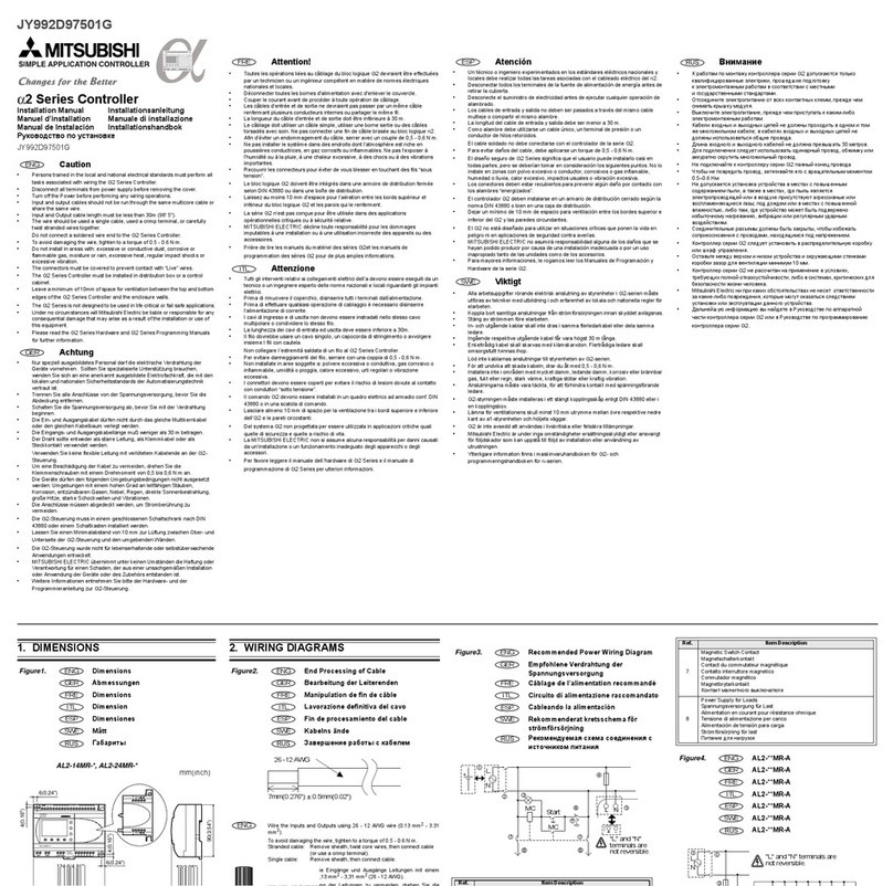
Mitsubishi MELSEC-A AJ71PT3 User manual
Other Mitsubishi Controllers manuals

Mitsubishi
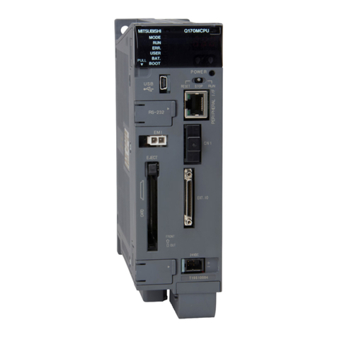
Mitsubishi QJ71MB91 User manual
Mitsubishi
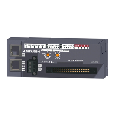
Mitsubishi NZ2GFCF-D62PD2 User manual

Mitsubishi
Mitsubishi Q62DA User manual
Mitsubishi
Mitsubishi MELSEC Q Series Owner's manual

Mitsubishi
Mitsubishi MELSEC Q Series User manual

Mitsubishi
Mitsubishi melservo-j2 series User manual

Mitsubishi
Mitsubishi MELSEC-A series User manual

Mitsubishi
Mitsubishi A Series User manual

Mitsubishi
Mitsubishi QD75P1N User manual
Mitsubishi
Mitsubishi MELSEC-F FX3U-4AD User manual

Mitsubishi
Mitsubishi A1SD75P1-S3 User manual
Mitsubishi
Mitsubishi FREQROL-SFJ User manual

Mitsubishi
Mitsubishi Q64TCRT User manual

Mitsubishi
Mitsubishi FX3G Series Owner's manual
Mitsubishi
Mitsubishi MELSEC iQ-R series User manual
Mitsubishi
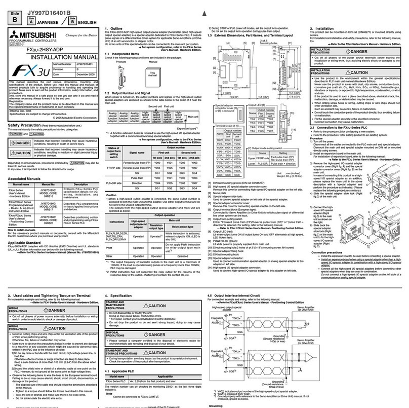
Mitsubishi FX3U-2HSY-ADP User manual

Mitsubishi
Mitsubishi FX0N-16NT User manual

Mitsubishi
Mitsubishi FX3UC Series User manual
Mitsubishi
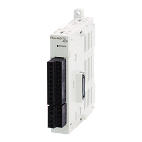
Mitsubishi MELSEC-F FX3U-4AD-TC-ADP User manual
Mitsubishi
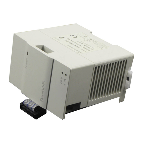
Mitsubishi FX2N-4AD-PT User manual
Popular Controllers manuals by other brands

Digiplex
Digiplex DGP-848 Programming guide

YASKAWA
YASKAWA SGM series user manual

Sinope
Sinope Calypso RM3500ZB installation guide

Isimet
Isimet DLA Series Style 2 Installation, Operations, Start-up and Maintenance Instructions

LSIS
LSIS sv-ip5a user manual

Airflow
Airflow Uno hab Installation and operating instructions
