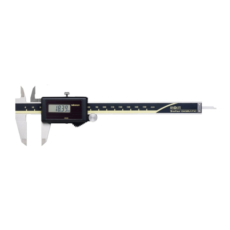
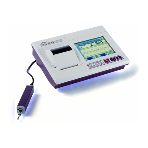
Mitutoyo SJ-301 User manual

Surface
Roughness Tester
User's Manual
No.99MBB091A5
SERIES No.178
Read this User’s Manual thoroughly
before operating the instrument. After reading,
retain it close at hand for future reference.
SJ-301

No. 99MBB091A
CONVENTIONS USED IN USER'S MANUAL
Safety Precautions
To operate the instrument correctly and safely, Mitutoyo manuals use various safety signs (Signal
Words and Safety Alert Symbols) to identify and warn against hazards and potential accidents.
The following signs indicate general warnings:
DANGER
Indicates an imminently hazardous situation which, if not avoided, will result in serious
injury or death.
WARNING
Indicates a potentially hazardous situation which, if not avoided, could result in serious
injury or death.
CAUTION
Indicates a potentially hazardous situation which, if not avoided, may result in minor or
moderate injury or property damage.
The following signs indicate specific warnings or prohibited actions, or indicate a mandatory action:
Alerts the user to a specific hazardous situation. The given example means “Caution,
risk of electric shock”.
Prohibits a specific action. The given example means “Do not disassemble”.
Specifies a required action. The given example means “Ground”.
i

No. 99MBB091A
CONVENTIONS USED IN USER'S MANUAL
On Various Types of Notes
The following types of notes are provided to help the operator obtain reliable measurement data
through correct instrument operation.
IMPORTANT •An
important note
is a type of note that provides information essential to the comple-
tion of a task. You cannot disregard this note to complete the task.
• An important note is a type of precaution, which if neglected could result in a loss of
data, decreased accuracy or instrument malfunction/failure.
NOTE A
note
emphasizes or supplements important points of the main text. A note supplies
information that may only apply in special cases (e.g.. Memory limitations, equipment
configurations, or details that apply to specific versions of a program).
TIP A
tip
is a type of note that helps the user apply the techniques and procedures de-
scribed in the text to their specific needs.
It also provides reference information associated with the topic being discussed.
Mitutoyo assumes no liability to any party for any loss or damage, direct or indirect,
caused by use of this instrument not conforming to this manual.
Information in this document is subject to change without notice.
© Copyright Mitutoyo Corporation. All rights reserved.
ii

No. 99MBB091A
PRECAUTIONS
To obtain the highest performance from this instrument and to use it safely, read this User’s
Manual prior to use.
This user's manual is intended for users of surface roughness testers SJ-301 and SJ-301R.
“SJ-301” is used in almost all descriptions of this user's manual.
If using model SJ-301R read this manual assuming “SJ-301” as “SJ-301R”.
Unless otherwise noted, the manual gives common information about the SJ-301 and SJ-
301R.
Observe the following precautions to get the most of the instrument and to attain high
accuracy for long time.
CAUTION
This instrument has a sharp stylus at the edge of the detector. Take care not to be
injured.
IMPORTANT • For the power supply, follow the conditions described on the AC adapter supplied.
Do not use other than the AC adapter provided.
• Do not disassemble the instrument unless otherwise specified in this User’s
Manual. It will result in instrument failure or damage. The instrument has been
rigorously adjusted and assembled at the factory.
• Do not drop or give impact to the Detector. The Detector is a precision part.
• Do not use the instrument in an environment where it is subject to dust or vibra-
tions. Also keep it as far apart from noise generator such as large power supply,
high-voltage relay switch as possible.
• Avoid using the instrument where there is sudden temperature change, and
operate it where the temperature is between 5°C and 40°C(RH: 85% maximum
without condensation). Do not operate/store the instrument close to a room heater
or in the direct sunlight.
• Store the instrument where the temperature can be controlled between -10 and 40°C.
• When mounting the Detector to the Drive unit, take care not to apply excessive
force to the Drive unit.
• Before connecting /detaching the connector or connecting cable, turn the power off.
• The stylus tip is machined precisely. Take care not to break it.
• Before measurement, wipe off oil or dust on the workpiece surface to be measured.
• Do not apply any load and impact onto the touch panel by placing or hitting with
foreign material. Touch panel may brake.
• Do not press the touch panel with sharp object such as a ball-point pen. Touch
panel may brake. Be sure to operate the touch panel with a finger or the provided
touch pen.
iii

No. 99MBB091A
WARRANTY
This instrument has been manufactured, adjusted, and inspected under rigorous quality
control system of Mitutoyo. In the event that this instrument should fail within one year from
the original date of purchase through normal use conforming to the User’s Manual provided
with the product, we will repair or replace it, at our option, free of charge, upon its prepaid
return to Mitutoyo.
This warranty shall not apply if the product has been subject to fair wear and tear, abuse
through misuse or improper use/handling/storage/maintenance/service/repair or through
adaptation/modification by the original purchaser or any third party without prior written
consent of Mitutoyo or as a result of damage by an actual disaster or circumstances beyond
the control of Mitutoyo.
This warranty is not transferable and is only valid within the country of the original purchase.
iv

No. 99MBB091A
CONTENTS
CONVENTIONS USED IN USER'S MANUAL ................................................................. i
PRECAUTIONS ...............................................................................................................iii
WARRANTY.................................................................................................................... iv
1 SJ-301 OVERVIEW .............................................................................................. 1-1
1.1 Outline of the SJ-301.................................................................................... 1-1
1.2 Standard SJ-301 Configuration .................................................................... 1-3
1.3 Nomenclature................................................................................................ 1-6
2 SHEET KEYS AND TOUCH PANEL OF SJ-301 ................................................ 2-1
2.1 Function of Sheet Keys ................................................................................ 2-1
2.2 Outline of the Touch Panel........................................................................... 2-5
2.3 Home Screen of the Touch Panel .............................................................. 2-10
2.4 Screen Hierarchy in the Touch Panel ........................................................ 2-13
2.5 List of Icons................................................................................................. 2-16
3 SETTING UP THE SJ-301 ................................................................................... 3-1
3.1 SJ-301 Setting .............................................................................................. 3-1
3.2 Attaching and Detaching the Drive/Detector Unit......................................... 3-2
3.2.1 Attaching and Detaching the Detector ............................................ 3-2
3.2.2 Connecting the Drive/Detector unit with the Display unit................ 3-5
3.3 Loading Printer Paper................................................................................... 3-6
3.4 Applying the Touch Panel Protection Sheet............................................... 3-10
3.5 Turning On/Off the Power Supply .............................................................. 3-12
3.5.1 Turning the power on/off ............................................................... 3-12
3.5.2 Setting the auto-sleep function in use of the built-in battery ........ 3-16
3.6 Setting Language, Date, and Unit .............................................................. 3-18
3.7 Carrying Case ............................................................................................. 3-25
4 MEASUREMENT OPERATION............................................................................ 4-1
4.1 Overall Measurement Flow........................................................................... 4-1
4.2 Calibration ..................................................................................................... 4-3
4.2.1 Calibration preparation .................................................................... 4-3
4.2.2 Performing calibration...................................................................... 4-6
4.3 Measurement .............................................................................................. 4-10
4.3.1 Setting the workpiece and SJ-301 ................................................ 4-10
4.3.2 Starting measurement ................................................................... 4-12
4.4 Switching the measured results display ..................................................... 4-13
4.4.1 Switching displayed parameters.................................................... 4-13
4.4.2 Displaying a measured profile ....................................................... 4-14
4.5 Printing Measured Results.......................................................................... 4-22
4.5.1 Print method .................................................................................. 4-22
4.5.2 Applying a memo to printed matter ............................................... 4-26
4.5.3 Changing print conditions .............................................................. 4-27
v

No. 99MBB091A
5 MODIFYING THE MEASUREMENT CONDITIONS ............................................ 5-1
5.1 Switching the Surface Texture Standard...................................................... 5-3
5.2 Switching the Measured Profile .................................................................... 5-6
5.3 Switching the Profile filters ........................................................................... 5-9
5.4 Switching the Cutoff length (lc)................................................................... 5-12
5.5 Modifying the Number of Sampling Lengths .............................................. 5-18
5.6 Setting the Evaluation Length to an Arbitrary Length ................................ 5-21
5.7 Modifying the Measuring Range................................................................. 5-24
5.8 Modifying the Traversing Speed................................................................. 5-27
5.9 Setting the Pre-Travel/Post-Travel to “OFF” .............................................. 5-30
5.10 Selecting the Display Parameters (Parameter Customization) .................. 5-33
5.10.1 Parameter Customization .............................................................. 5-33
5.10.2 Setting the calculation conditions when Sm, Pc, or Ppi is
selected.......................................................................................... 5-39
5.10.3 Setting the calculation conditions if mr[c] is selected ................... 5-42
5.10.4 Setting the calculation conditions if mr is selected ....................... 5-45
5.10.5 Setting the calculation conditions if dc is selected........................ 5-49
5.10.6 Setting the calculation conditions if HSC is selected.................... 5-53
5.10.7 Setting the calculation conditions when selecting a profile motif
(MOTIF.R/MOTIF.W) ..................................................................... 5-56
5.11 Setting the GO/NG Judgment Function...................................................... 5-59
5.12 Setting the Drive Unit.................................................................................. 5-65
5.13 Deleting Unnecessary Data ........................................................................ 5-68
5.14 Modifying the Tilt Compensation Specification........................................... 5-73
5.15 Modifying the Calibration Conditions .......................................................... 5-80
5.16 Resetting to the default settings ................................................................. 5-86
6 RECALCULATION WITH THE MODIFIED MEASUREMENT CONDITIONS..... 6-1
7 STATISTICAL PROCESSING OF MEASUREMENTS........................................ 7-1
7.1 Overview of Statistical Processing ............................................................... 7-1
7.2 Execution of Statistical Processing............................................................... 7-2
7.3 Settings Related to Statistical Processing.................................................... 7-7
7.4 Displaying the Frequency Histogram and Printing the Statistical Data ..... 7-11
7.5 Saving and Reading Statistical Data .......................................................... 7-13
8 SAVE/READ OF MEASUREMENTS, MEASUREMENT CONDITIONS AND
STATISTICAL DATA............................................................................................ 8-1
8.1 Data To Be Saved and Storage Media ........................................................ 8-2
8.2 Saving/Recalling the Measurement Conditions............................................ 8-5
8.2.1 Saving the measurement conditions ............................................... 8-5
8.2.2 Recalling the measurement conditions ......................................... 8-15
8.3 Saving/Reading Measured Profile Data ..................................................... 8-23
8.3.1 Saving the measured profile data ................................................. 8-23
8.3.2 Reading the measured profile data ............................................... 8-30
8.4 Saving/Reading the Statistical Data ........................................................... 8-32
8.4.1 Saving the statistical data.............................................................. 8-32
8.4.2 Reading the statistical data ........................................................... 8-35
8.5 Memory Card Formatting and File Deletion ............................................... 8-38
8.5.1 Formatting the memory card ......................................................... 8-38
8.5.2 Deleting a file stored in the memory card ..................................... 8-41
vi

No. 99MBB091A
vii
9 SPC OUTPUT AND DATA COMMUNICATION .................................................. 9-1
9.1 SPC Output................................................................................................... 9-1
9.2 Communicating with a PC ............................................................................ 9-6
10 INSTALLING THE SJ-301 WITH OPTIONAL
ACCESSORIES .................................................................................................. 10-1
11 MAINTENANCE AND INSPECTION OF SJ-301............................................... 11-1
11.1 Daily Care ................................................................................................... 11-1
11.2 Detector Retraction Procedure and Cancellation ....................................... 11-4
11.3 Recharging the Battery ............................................................................... 11-8
11.4 Replacing the Battery Pack ...................................................................... 11-12
11.5 Testing the Touch Panel........................................................................... 11-15
12 TROUBLESHOOTING........................................................................................ 12-1
13 SPECIFICATIONS .............................................................................................. 13-1
13.1 Detector....................................................................................................... 13-1
13.2 Drive Unit .................................................................................................... 13-1
13.3 Display Unit ................................................................................................. 13-2
13.3.1 Compatible surface texture standard ............................................ 13-2
13.3.2 Measured profiles and applicable filters........................................ 13-2
13.3.3 Cutoff length/Sampling length, Number of sampling lengths, and
Sampling interval ........................................................................... 13-2
13.3.4 Roughness parameters and display range ................................... 13-3
13.3.5 Evaluation length ........................................................................... 13-4
13.3.6 Measuring range and resolution.................................................... 13-4
13.3.7 Pre-travel/Post-travel length .......................................................... 13-4
13.4 Power Supply .............................................................................................. 13-5
13.5 Temperature/Humidity Range ..................................................................... 13-5
13.6 External Dimensions and Mass .................................................................. 13-6
13.7 Optional Accessories .................................................................................. 13-7
13.8 Consumables .............................................................................................. 13-8
13.9 SPC Output Specifications ......................................................................... 13-8
13.10RS-232C Communication Specifications ................................................. 13-10
14 REFERENCE INFORMATION............................................................................ 14-1
14.1 Surface Texture Standard........................................................................... 14-1
14.1.1 Evaluation according to JIS B0601-1982 ...................................... 14-1
14.1.2 Evaluation according to JIS B0601-1994 ...................................... 14-2
14.1.3 Evaluation according to DIN.......................................................... 14-3
14.1.4 Evaluation according to JIS B0601-2001 and ISO ....................... 14-4
14.1.5 Evaluation according to ANSI........................................................ 14-5
14.2 Measured Profile and Filters....................................................................... 14-6
14.2.1 Measured profile ............................................................................ 14-6
14.2.2 Filters ............................................................................................. 14-9
14.2.3 Difference of filter characteristics ................................................ 14-12
14.2.4 Amplitude characteristic of 2RC and Gaussian filters................. 14-13
14.3 Mean line compensation........................................................................... 14-14
14.4 Traversing Length ..................................................................................... 14-15

No. 99MBB091A
14.5 Definitions of the SJ-301 Roughness Parameters ................................... 14-18
14.5.1 Arithmetic mean deviation of the profile, Ra ............................... 14-18
14.5.2 Root-mean-square deviation of the profile, Rq ........................... 14-18
14.5.3 Maximum height of the profile, Ry (JIS’82, JIS’94)..................... 14-19
14.5.4 Ten-point height of irregularities, Rz (JIS’82, JIS’94) ................. 14-20
14.5.5 Maximum height of the profile, Ry (DIN, ANSI) .......................... 14-21
14.5.6 Maximum height of the profile, Rz (DIN, ISO, ANSI, JIS’01) ..... 14-21
14.5.7 Maximum profile height, Rp (DIN, ISO, JIS’94, JIS’01) .............. 14-21
14.5.8 Maximum profile valley depth, Rv (DIN, ISO, JIS’94, JIS’01)..... 14-22
14.5.9 Total height of the profile, Rt....................................................... 14-22
14.5.10 Skewness of the profile, Sk......................................................... 14-22
14.5.11 Kurtosis of the profile, Ku ............................................................ 14-23
14.5.12 Arithmetic mean slope of the profile, Da..................................... 14-23
14.5.13 Root-mean-square slope of the profile, Dq ................................. 14-23
14.5.14 Mean width of the profile elements, Sm (JIS, ISO, DIN) ............ 14-24
14.5.15 Peak count, Pc (JIS, ISO, DIN)................................................... 14-24
14.5.16 Peak count, Ppi (JIS, ISO, DIN).................................................. 14-24
14.5.17 Material ratio of the profile, mr[c]
(tp= material ratio of the profile).................................................. 14-25
14.5.18 Material ratio of the profile, mr .................................................... 14-25
14.5.19 Profile section height difference (plateau ratio), dc..................... 14-26
14.5.20 Material ratio curve of the profile (Abbott Firestone curve),
BAC.............................................................................................. 14-26
14.5.21 Profile height amplitude curve, ADC ........................................... 14-27
14.5.22 Core roughness depth, Rk
(Depth of the roughness core profile) ......................................... 14-28
14.5.23 Reduced peak height, Rpk
(Average height of the protruding peaks above the roughness
core profile).................................................................................. 14-28
14.5.24 Reduced valley depth, Rvk
(Average depth of the profile valleys projecting through the
roughness core profile)................................................................ 14-28
14.5.25 Material portion, Mr1.................................................................... 14-28
14.5.26 Material portion, Mr2.................................................................... 14-28
14.5.27 Peak area, A1.............................................................................. 14-28
14.5.28 Valley area, A2 ............................................................................ 14-28
14.5.29 Measuring volume Vo.................................................................. 14-29
14.5.30 Mean peak-to-valley height points, R3z ...................................... 14-29
14.5.31 Mean spacing of local peaks of profile, S ................................... 14-30
14.5.32 Developed profile length Lo......................................................... 14-30
14.5.33 High spot count, HSC.................................................................. 14-31
14.6 Parameters Related With Motif................................................................. 14-32
14.6.1 How to obtain roughness motifs.................................................. 14-32
14.6.2 Roughness motif parameters ...................................................... 14-35
14.6.2.1 R .................................................................................... 14-35
14.6.2.2 AR.................................................................................. 14-35
14.6.2.3 Rx .................................................................................. 14-35
14.6.3 How to obtain waviness motifs.................................................... 14-35
viii

No. 99MBB091A
ix
14.6.4 Waviness motif parameters ......................................................... 14-36
14.6.4.1Wte.................................................................................. 14-36
14.6.4.2Wx................................................................................... 14-36
14.6.4.3W..................................................................................... 14-36
14.6.4.4AW .................................................................................. 14-36
SERVICE NETWORK

1
1 - 1
No. 99MBB091A
SJ-301 OVERVIEW
1.1 Outline of the SJ-301
The Surftest SJ-301 is a stylus type surface roughness measuring instrument developed for
shop floor use. The SJ-301 is capable of evaluating surface textures with a variety of param-
eters according to various national standards and international standard. The measurement
results are displayed digitally/graphically on the touch panel, and output to the built-in
printer.
This section explains the surface roughness measurement principle and the features of the SJ-301.
■SJ-301 surface roughness measurement principle
The stylus of the SJ-301 detector unit traces the minute irregularities of the workpiece
surface. Surface roughness is determined from the vertical stylus displacement produced
during the detector traversing over the surface irregularities. The measurement results are
displayed digitally/graphically on the touch panel.
2. The vertical stylus displacement
produced while tracing the workpiece
surface is converted into electrical signals
.
AC adapter
5.The measured and/or
statistical data is printed
out.
3.The electrical signals are subject to
various calculation processes.
Workpiece surface
Stylus
Detector traverse direction
1.The detector stylus traces
the workpiece surface
(measured surface).
4.The calculation results
(surface roughness) are
displayed on the touch panel.

1 - 2
No. 99MBB091A
■Features of SJ-301●Lightweight and portable
The SJ-301 is lightweight (1.4kg approx.), and has excellent portability. It is about the size
of a notebook computer. With the supplied carrying case, the SJ-301 can be slung over the
shoulder. Furthermore, the built-in battery will facilitate roughness measurement on the
shop floor or at other sites where there may be no AC power supply.
●Wide measuring range and a long list of roughness parameters
The SJ-301 has a maximum measuring range of 350 µm (-200 to +150 µm) or 14000 µ in
(-8000 to +6000 µ in) and supports various surface parameters for evaluating surface
texture.
●Auto-sleep function for power conservation
With auto-sleep set to ON under operation on the built-in battery, the SJ-301 automatically
turns the power off (enters the auto-sleep state) if it is not in operation for 5 minutes even
when the power is on. The SJ-301 still retains the set measurement conditions in memory
even if the power is turned off.
●Measured profile display on the touch panel
The SJ-301 can display a measured profile on the touch panel.
●Easy-to-operate touch panel
Measurement conditions can be set up with the touch panel. The touch panel displays
various menus, etc., clearly and according to procedure. This makes the SJ-301 easy to
operate.
●Internal memory and memory card facilitate storage of measurement conditions and data
Five sets of measurement conditions can be stored in the internal memory. An additional
20 sets of measurement conditions and measurement data can be stored in a memory card.
●Built-in printer facilitates record of measurement results
The built-in printer can operate manually or automatically for printing the measurement
conditions, measurement results, and measured profile.
●Includes statistical processing function
A histogram, etc., can be created with the statistical processing function.
●Compatible with various surface texture standards
The SJ-301 is capable of performing surface roughness measurement according to various
standards that include JIS-B-0601-2001, JIS-B-0601-1994, JIS-B-0601-1982, DIN, ISO,
and ANSI.

1-3
No. 99MBB091A
1. SJ-301 OVERVIEW
1.2 Standard SJ-301 Configuration
This section explains the standard configuration, the standard sets, and the typical use of an
optional accessories.
Standard SJ-301 configuration
After unpacking, confirm that all items given below are present in your SJ-301 package.
Display unit Drive/Detector unit
Drive unit
Detector
.oNledoM )Nm4:ecrofgnirusaeM(N)m57.0:ecrofgnirusaeM(
)mmrof(*3-359-871 )mm/hcnirof(*3-459-871 )mmrof(*3-259
-871 )mm/hcnirof(*3-559-871
093-871962-871
2-032-871
3-142-871
.desuegatlovCAehtotgnidrocca.oNehtotdeddasiwo
lebsexiffusehtfoenO:* CAV042:E,CAV022:CD,CAV)022(032:D,CAV011:C,CAV021:A,CAV001:enoN
Set No.
Detector unit
Drive unit
Display unit
.oNledoM R103-JS
)Nm4:ecrofgnirusaeM(
R103-JS
)Nm57.0:ecrofgnirusaeM(
.oNteS )mmrof(*089-871 )mm/hcnirof(*78
9-871 )mmrof(*099-871 )mm/hcnirof(*799-871
tinurotceteD903-871962-871
tinuevirD352-871
tinuyalpsiD-3142-871
.desueg
atlovCAehtotgnidrocca.oNehtotdeddasiwolebsexiffusehtfoenO:* CAV042:E,CAV022:CD,CAV)022(032:D,CAV011:C,
CAV021:A,CAV001:enoN
Standard SJ-301 for MAC configuration
.oNledoM CAMrofR103-JS
)Nm4:ecrofgnirusaeM(
)mm/hcnirof(A399-871
082-871
532-871
3-142-871
Set No.
Detector unit
Drive unit
Display unit
IMPORTANT Only use the supplied AC adapter for this instrument. Otherwise, not only the
adapter but that equipment it is used with may be damaged.

1 - 4
No. 99MBB091A
Ra 3.05m 9.9m
Rmax
(Ry)
Carrying case
No.12BAA781 Connecting cable (1 m/40")
No. 12BAA686
Touch panel
protection sheet (1pc)
No. 12BAA690
Printer paper
No. 270732 (5 rolls)
Touch pen
No. 12BAA689
Power cord (AC adapter)
AC adapter
No. 357651
Precision roughness
specimen (with case)
No.178-601 (mm)
No.178-602 (mm/inch) Screwdriver
No. 541106
Standard accessories
Support feet (pair)
No. 12AAA216 User’s Manual
No.99MBB091A Quick Reference Manual
No. 99MBB092A
Nosepiece for cylinder
No. 12AAA218
Nosepiece for
flat surface
No.12AAA217
Screws
No.355556
IMPORTANT Only use the supplied AC adapter for this instrument. Otherwise, not only the
adapter but that equipment it is used with may be damaged.
■SJ-301 standard set No.
)Nm4:ecrofgnirusaeM(103-JS)Nm57.0:ecrofgnirusaeM(103-JS
rewoPdrocegatloveniL
.oNteS.oNteS
mmhcni/mmmmhcni/mm
C3-
359-8713-459-871C3-259-8713-559-871569039CAV)001(011
A3-359-871A3-459-871A3-259-871A3-559-871669039CAV021
D3-359-
871D3-459-871D3-259-871D3-559-871769039CAV)022(032
CD3-359-871CD3-459-871CD3-259-871CD3-559-871997FAB21CAV022
E3-
359-871E3-459-871E3-259-871E3-559-871416899CAV042
K3-359-871-K3-259-871-438FAB21CAV022
■SJ-301R set No.
)Nm4:ecrofgnirusaeM(R103-JS)Nm57.0:ecrofgnirusaeM(R103-JS
rewoPdrocegatloveniL
.oNteS.oNteS
mmhcni/mmmmhcni/mm
C
089-871789-871C099-871799-871569039CAV)001(011
A089-871A789-871A099-871A799-871669039CAV021
D089-871D789-871D099-87
1D799-871769039CAV)022(032
CD089-871CD789-871CD099-871CD799-871997FAB21CAV022
E089-871E789-871E099-871E799-87141689
9CAV042
K089-871-K099-871-438FAB21CAV022

1 - 5
No. 99MBB091A
1. SJ-301 OVERVIEW
■SJ-301R for MAC set No.
CAMrofR103-JS )Nm4:ecrofgnirusaeM( rewoPdrocegatloveniL
.oNteS
hcni/mm
A399-871669039CAV021
■Consumables SJ-301 consumables include the following items:
selbamusnoCytQ.oNtraP
repapretnirP5237072
kcapyrettabni-tliuB1886AAB21
teehsnoitcetorplenaphcuoT1096AAB21
teehsno
itcetorplenaphcuoT01698AAA21
■Optional accessories
Depending on the shape of the part features to be measured, it may be necessary to use
optional accessories to set up the SJ-301. Consider the shape of the workpiece when purchas-
ing optional accessories.
The following illustrates an application of optional accessories.
Drive unit
Adapter for vertical application
Adapter for
vertical application
Workpiece
Hold down by hand.
TIP For details of optional accessories refer to “Chapter 10 INSTALLING THE SJ-301
WITH OPTIONAL ACCESSORIES”.

1 - 6
No. 99MBB091A
1.3 Nomenclature
This section gives the name of each part of the Drive/Detector unit and Display unit.
■Drive/Detector unit and Display unit
The SJ-301 consists of the display unit and drive/detector unit. The drive/detector unit can be
safely stored in the compartment inside the display unit.
Detector
Drive/Detector unit Display unit
Drive unit
TIP For information about connection between the Drive/Detector unit and Display unit
refer to “3.2 Attaching and Detaching the Drive/Detector Unit”.
NOTE Check the drive unit used and the drive unit settings in the display unit before using
the unit. If there is an error in setting the drive unit, an error message such as
“DRIVE ERROR 1” and “OVERRANGE” may appear, disabling measurement. For
information about the drive unit setting, refer to “5.12 Setting the Drive Unit”.
■Drive/Detector unit nomenclature
Skid (Stylus)
Side view
Drive unit
Detector Support feet mounting groove
Nosepiece mounting screw holes

1 - 7
No. 99MBB091A
1. SJ-301 OVERVIEW
■Display unit nomenclature
Inside view
with the cover open
Magnet
Sheet keys
Drive/Detector
unit can be
housed
Touch pen
can be housed
Drive/detector unit cover (back side)
Lock lever
Drive/detector unit
compartment cover
Touch pen holder
Touch pen holder is
rotated to this position.
Printer cover
Touch panel
Touch pen holder
Bottom view
Battery cover

1 - 8
No. 99MBB091A
■Nomenclature and function of the Display unit connectors
●Display unit rear view
AC adapter
connector Battery
switch Reset
button
Volume adjustment control
RS-232C
switch RS-232C
connector SPC
connector
Button masking switch
Contrast adjustment control
• AC adapter connector
Connects the AC adapter cable for power supply.
• Battery switch
Turns on/off the battery power to the circuit. Leave it on normally.
• Contrast adjustment control
Adjusts the contrast of the touch panel.
• Button masking switch
Restricts some of the functions of the touch panel.
• Reset button
Restores the factory-set default conditions.
• Volume adjustment control
Adjusts the volume of the beep generated when the touch panel is pushed. To adjust the
volume, turn the control with a small flat-blade screwdriver.
• RS-232C switch
Switches between the normal mode and the communication mode.
• RS-232C connector
Connects the RS-232C cable.
• SPC connector
Connects the SPC cable.

1 - 9
No. 99MBB091A
1. SJ-301 OVERVIEW
●Display unit side view
Drive/detector
unit cable connector
Memory card slot
POWER key
• POWER key
Turns the power supply of the SJ-301 on/off.
• Memory card slot (with protection cover)
Slot to insert a memory card (option) into.
First remove the protection cover to insert the card.
• Driver/detector unit connector
Connects the cable of the Driver/Detector unit.

1 - 10
No. 99MBB091A
■SJ-301 Functions Table Major functions of the SJ-301
noitcnuFecnerefeR
putesnoitidnocgnirusaeM5.pahC
noitarbilaC2.4
tnemerusaemssenhguoR3.4
tnemgdujGN/OG11.5
tluser
tnemerusaemfonoitaluclaceR6.pahC
seulavretemarapfognissecorplacitsitatS7.pahC
stnemerusaemfotuotnirP5.4
sno
itidnoctnemerusaemfollac/evaS8.pahC
stniopatadeliforpfollac/evaS8.pahC
atadlacitsitatsfollac/evaS8&7.pahC
e
pacserotceteD2.11
noitcelesegaugnaL6.3
tuptuoatadCPS1.9
noitacinummocC232-SR2.9
noitazilaitininoitidnoctnemer
usaeM )seulavtluafedotteseR( 61.5
noitcnufreluR2.4.4
noitcnufeteledataD31.5
■Major specifications of the SJ-301
Table Major specifications of SJ-301 including measured profiles, parameters, etc.
metIsnoitpircseD
eliforpderusaeMW.FITOM,R.FITOM,6774NID,R,P
retemaraP ,z3R,rm,cP,S,mS,vR,pR,tR,qR,zR,yR,aR δ,drm,CSH,c Δ,ipP,oL,a
,uK,kS Δ,xW,WA,W,RA,R,2A,1A,2rM,1rM,kR,kvR,kpR,xR,q
oV,etW
retliFSSUAG,57CP,CR2
htgne
lffotuC )ni3.,1.,30.,10.,300.(mm8,5.2,8.0,52.0,80.0
htgnelgnilpmasforebmuN)htgnelyrartibra(Ldna,5,3,1
noi
tuloseR10.0 )stib01(m
metiatadlacitsitatS ,)eliforprepretemarapeno(noitaiveddradnatS,muminiM,mumixaM,nae
M)eliforprepsretemarapeerht,LL/LU(tnemgdujGN/OG
yticapacyromemlanretnIselifnoitidnoctnemerusaem5otpU
O/I
lanretxE)noitpo(dracyromeM,tuptuoCPS,C232-SR
ylppusrewoP )negordyh-lekcin(kcapyrettabni-tliuB,retpadaCA
Table of contents
Other Mitutoyo Test Equipment manuals
Popular Test Equipment manuals by other brands

Seaward
Seaward PrimeTest 300 operating instructions

Badger Meter
Badger Meter Flo-tech PFM Series Installation & operation manual

EUTECH INSTRUMENTS
EUTECH INSTRUMENTS ECOTESTR EC HIGH instruction manual

JYE Tech
JYE Tech DSO 068 Assembly guide

SCS
SCS TB-9031 user guide

Alcovisor
Alcovisor Mercury operating manual

Alps Electric
Alps Electric FlexPitch Operator's manual

Triplett
Triplett Fox Jr. instruction manual

GE
GE MicroVersaTrip TVTS1 manual

Advanced Power technologies
Advanced Power technologies ECLIPSE Application guide

APPA
APPA VP-1 user manual

Baker Instrument Company
Baker Instrument Company D6000 DIGITAL TROUBLESHOOTING PROCEDURES & FAULT LISTING