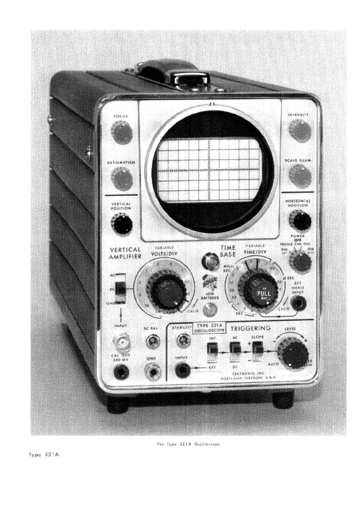
Tektronix 321 A User manual
Other Tektronix Test Equipment manuals

Tektronix
Tektronix TBS2000B Series User manual

Tektronix
Tektronix 212 User manual

Tektronix
Tektronix RM3000 User manual

Tektronix
Tektronix T202 User manual

Tektronix
Tektronix 2445B User manual

Tektronix
Tektronix P6042 PROBE User manual

Tektronix
Tektronix TBS1000B Series User manual

Tektronix
Tektronix 454A User manual

Tektronix
Tektronix 2445 User manual

Tektronix
Tektronix 2465 User manual

Tektronix
Tektronix MDO4000C Series User manual

Tektronix
Tektronix TMT4 Use and care manual

Tektronix
Tektronix 519 User manual

Tektronix
Tektronix TDS1000 Series User manual

Tektronix
Tektronix 575 series User manual

Tektronix
Tektronix 2215A Assembly instructions

Tektronix
Tektronix SD-24 User manual

Tektronix
Tektronix 2 Series Instruction manual

Tektronix
Tektronix TU-7 User manual

Tektronix
Tektronix 7603 User manual