iii
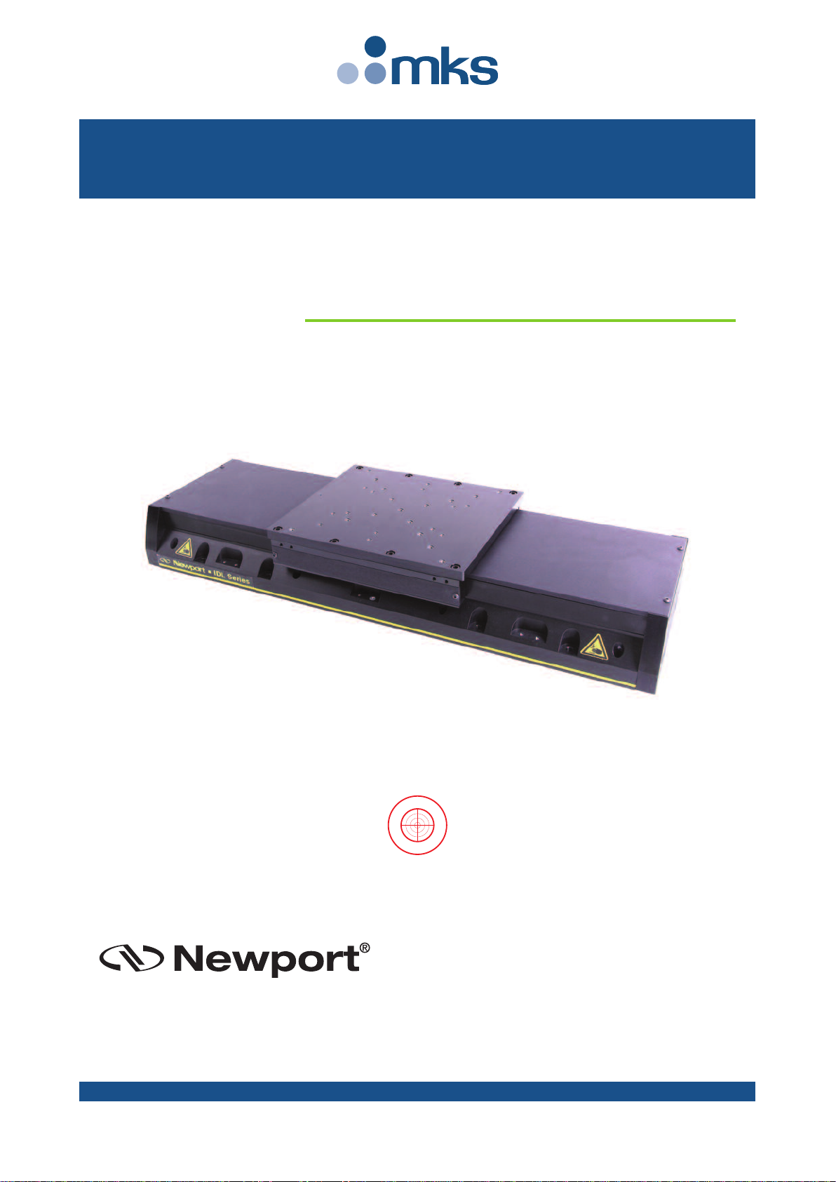
IDL225-LM Serie Long Travel Indu trial Linear Stage
Table of Contents
Warranty .................................................................................................................ii
Declaration of Incorporation ................................................................................v
Definitions and Symbols.......................................................................................vi
Warnings ...............................................................................................................vii
Caution ...................................................................................................................ix
1.0 — Introduction.................................................................................1
2.0 — Description ...................................................................................2
2.1 Design Details ............................................................................................2
3.0 — Characteristics............................................................................3
3.1 Definitions..................................................................................................3
3.2 Mechanical Specifications .......................................................................4
3.3 Hard Stop: Speed Limitation Versus Load .............................................4
3.4 Load Characteristics and Stiffness .........................................................5
3.5 Stage Weights ............................................................................................5
4.0 — Drive and Motor.........................................................................6
4.1 Motor characteristics (Direct Drive Brushless Motor)........................6
4.2 Command Signals......................................................................................6
4.3 Sensor Positions........................................................................................7
4.4 Position Feedback Signals........................................................................7
4.5 General Wiring...........................................................................................8
4.6 Pinouts........................................................................................................8
Hall Effect Sensor (SUB-D15F Connector) ..............................................8
Encoder (SUB-D15M Connector).............................................................8
Encoder (SUB-D26HDM Connector on E5820A Adapter) .....................9
Motor (DB9W4M Connector)...................................................................9
4.7 IDL225-LM Cable Wirings .........................................................................9
4.8 Air Tube....................................................................................................10
5.0 — Stage Installation.....................................................................11
5.1 Unpacking ................................................................................................11
5.2 Setting Up.................................................................................................11
5.3 Mounting Conditions ..............................................................................13
5.4 Air Blowing...............................................................................................13
A1044F0 - EDH0361En1050 — 02/20