Mo-vis P002-33 Guide

User & Installation Manual
EN
Joystick Interface e-fix 25
P002-33
Contact & Product
mo-Vis BVBA
Biebuyckstraat 15 D
9850 Nevele - Belgium
Website: www.mo-vis.com
E-mail: [email protected]om
Telephone: +32 9 335 28 60
User & Installation manual
Produced and published by
mo-Vis bvba, Belgium
Edition 1, April 2016
Manual item: D-P002-33-70-00

2
Contents
Contact & Product -------------------------------------------------------------------- 1
Contents -------------------------------------------------------------------------------- 2
Important information about this manual-------------------------------------- 2
Support, scrapping and spare parts ---------------------------------------------- 3
Warranty-------------------------------------------------------------------------------- 3
Safety precautions-------------------------------------------------------------------- 5
Design and function of the e-fix 25 interface ---------------------------------- 6
Installation instructions ------------------------------------------------------------- 7
Using the Joystick Interface e-fix 25---------------------------------------------11
Maintenance--------------------------------------------------------------------------12
Technical data ------------------------------------------------------------------------13
Important information about this Manual
Congratulations for choosing a mo-Vis product! If you would like to
learn more about mo-Vis and its products, we invite you to visit our
website: www.mo-vis.com.
Before you install or begin using this product, it is important that you
read and understand the content of these installation and operating
instructions, the safety instructions in particular.
The installation instructions will guide you as an installer through the
options and possibilities with the mo-Vis product.
The operating instructions are primarily intended to acquaint you
with the functions and characteristics of the mo-Vis product and how
you can use it in the best manner possible. They also contain
important safety and maintenance information, as well as describe
possible problems that can arise during use. Always keep the
operating instructions handy in connection with your wheelchair,
since the need for important information can arise concerning its use,
safety and maintenance.
All information, pictures, illustrations and specifications are based on
the product information that was available at the time of printing.
Pictures and illustrations shown in these instructions are

e-fix 25 Interface manual 3
representative examples and are not intended to be exact depictions
of the various parts of the product.
We reserve the right to make changes to the product without prior
notice.
Ordering documentation
You can download additional copies of this User & Installation
manual on the mo-Vis website: www.mo-vis.com.
Support, scrapping and spare parts
Technical support
In case of technical problems, we advise you contact your dealer.
If the dealer is not available, or unknown, please contact mo-Vis bvba
Always state the device serial number when contacting mo-Vis. This
ensures you are provided with the correct information.
Spare parts and accessories
Spare parts and accessories must be ordered by the dealer at mo-Vis
bvba.
Scrapping & recycling
For scrapping, adhere to your local waste legislation.
Dispose of obsolete electronic parts responsibly in accordance with
local recycling regulations.
Warranty
mo-Vis bvba warrants the unit to be free from defects in material and
workmanship for a period of 2 years under proper use, care and
service. All warranties only cover parts and do not extend beyond the
initial purchaser from an authorised mo-Vis dealer.
Start of the warranty period
Each warranty shall begin on the date the product is first delivered to
the customer.

4
Repair and replacement
For warranty service, we advise you contact the dealer from whom
the product was purchased. In the event of a defect in material or
workmanship, the dealer must obtain a return authorisation (RA)
number from mo-Vis and the product must be shipped to a service
centre designated by mo-Vis. mo-Vis will repair or, at mo-Vis’ option,
replace any product covered by the warranty.
Disclaimer and Limitations of Remedies
The express warranties set forth in this agreement are in lieu of all
other warranties of merchantability or fitness of purpose. In no event
shall mo-Vis be liable for any direct, indirect, incidental or
consequential damages resulting from any defect in this product.
Warranty of parts subject to “normal wear and tear” (e.g. pads,
joystick balls, batteries …) are not covered in the warranty except as
it applies to defects in material or construction.
Amendments
No person is authorised to alter, extend or waive the warranties of
mo-Vis.
Voiding of warranties
The foregoing warranties are contingent upon the proper installation,
use, maintenance and care of the product. The warranty will be void
if the product has been installed or used improperly, or if it has been
repaired or any part replaced by persons other than mo-Vis or an
authorised dealer. The unit is considered as a non-serviceable part.
The addition of equipment or features that are not manufactured or
recommended by mo-Vis could affect the intended function of the
mo-Vis product and may invalidate the warranty.
Understanding usage
The health care professional (authorised installer) is responsible for
understanding the intended use of the mo-Vis equipment, the
specifications and its programming parameters. mo-Vis cannot be
held responsible for damage caused by incorrect installation or
incorrect use of the product. Misuse, mishandling, or storage is not
covered by this warranty.

e-fix 25 Interface manual 5
Safety precautions
General
The e-fix 25 interface is intended to be fitted on any power
wheelchair with the e-fix 25 drive package to connect a mo-Vis Omni
compatible device.
Incorrect use or installation may lead to risk of injury to the user and
damage to the wheelchair or other property.
In order to reduce these risks, you should carefully read this
instruction manual, paying particular attention to the safety
instructions and warning texts.
Any unauthorised use of the product may lead to increased risk of
accident. Carefully follow the recommendations in this manual in
order to prevent accidents from use.
The e-fix 25 interface, integrated cabling included, is a non-
serviceable part.
In case of doubt for alterations and adjustments, always contact a
qualified service engineer.
Warning labels
This manual contains the following warning labels, which are
intended to draw attention to situations that could lead to unwanted
problems, e.g. personal injury or damage to the wheelchair.
CAUTION!
Please use caution where this symbol appears.
WARNING!
Please use extreme caution where this warning symbol appears.
Failure to observe warnings can lead to personal injury or property
damage.
CAUTION!
Limited liability
mo-Vis accepts no liability for personal injury or damage to property
that may arise from the failure of the user or other persons to follow
the recommendations, warnings and instructions in this manual.

6
CAUTION!
EMC Requirements
The electronics of a power wheelchair and its options can be
affected by external electromagnetic fields (for example from mobile
telephones). Similarly, the electronics of the wheelchair or options
themselves can also emit electromagnetic fields that can affect the
immediate surroundings (for example certain alarm systems in
businesses).
The limit values for Electromagnetic Compatibility (EMC) with
respect to power wheelchairs are set in the harmonised standards
for the EU in the Medical Devices Directive, No. 93/42/EEC. The
Adjustable Fused Power Supply complies with these limit values.
WARNING!
Assembly
The unit should only be installed or adjusted by a qualified service
engineer or someone with adequate knowledge to perform the
adjustment in an expert manner.
Maintenance and service
Carry out only the service and maintenance activities specified in this
manual, as long as you comply with the demands stated in this
manual for a specific action. All other service, alterations to and
interventions on the E-fix 25 interface must be carried out by a
qualified service engineer or someone with adequate knowledge to
perform the adjustment in an expert manner. In case of doubt,
contact a qualified service engineer or mo-Vis.
Use only spare parts or accessories approved or recommended by
mo-Vis. All other use could lead to changes which might impair the
function and safety of the product. It could also lead to the warranty
becoming void.
Design and function of the e-fix 25 interface
Intended use
The e-fix 25 interface can be used to connect any mo-Vis Omni
joystick to a power wheelchair with the e-fix 25 drive package.
Do not use the device to connect any non mo-Vis Omni device.

e-fix 25 Interface manual 7
Indicator LED
When in use, a green LED on e-fix 25 interface indicates the proper
functioning of the unit.
Connections
The following connections are available on the e-fix 25 interface:
9-pole sub-d connector to connect a mo-Vis Omni Joystick.
Red and green jack socket of 3.5 mm to switch on/off the e-fix
system.
The red jack socket is to plug in the red plug of the Omni joystick
The green jack socket can be used to connect to the e-fix
optibox (3.5 mm jack mono extension lead not included). This
switches the power supply.
Installation instructions
Preparations
Qualified service engineer
Only a qualified service engineer may install the Joystick interface e-
fix 25.
Installation plan
Set up an installation plan before beginning the installation. Based on
the users’ needs and with actual measurements of the wheelchair,
this plan should specify where the unit will be placed, and how the
cabling will be guided.
Serial number sticker
An additional serial number sticker can be found in the package and
should be adhered to the back of this manual.
Connecting the cabling to the Joystick e-fix 25 interface
WARNING!
All wheelchair electronics must be switched off before connecting
any cabling.
8
To connect the cabling to the Joystick e-fix 25 interface, proceed as
follows:
1. Place the unit according to the installation plan on the wheelchair.
WARNING!
Firmly secure the unit to the wheelchair.
You can e.g. use Velcro of double-sided tape on the back of the unit.
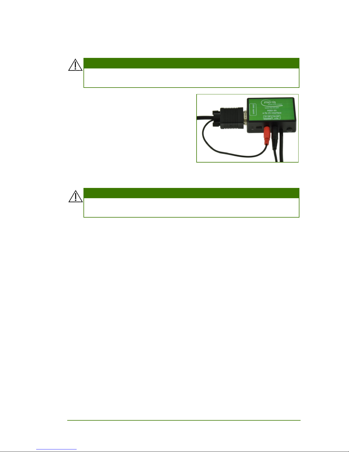
2. Connect the Omni Joystick
cabling to the Omni Joystick
input. Insert the Sub-d plug into
the sub-d connector, and the red
jack plug into the red jack
socket.
3. If needed to switch the power
supply, connect the green socket
with a 3.5 mm jack mono extension lead to the e-fix optibox.
4. Guide and secure all cabling according to the installation plan.
WARNING!
Mind damaging the unit and wiring. Make sure the cabling is
mounted in such a way the excessive wear and tear is avoided.
5. Insert the e-fix connection cable of the e-fix 25 interface into the
wheelchair e-fix 25 system to connect the device.
6. Switch the wheelchair electronics on.
The green LED on the unit switches on.
7. If needed, use the dial on the e-fix 25 Joystick to set the speed. By
default, the e-fix 25 interface is programmed to take the original
speed potentiometer of the joystick.
8. Connect the e-fix 25 interface to a PC with the mini USB
connection. Calibrate and configure the joystick with the
Configurator software.
9. Test the usage of the joystick according to the joystick test plans.

e-fix 25 Interface manual 9
Calibrating & configuring with the mo-Vis Configurator software
Whenever connecting or replacing a mo-Vis joystick it is advised to
calibrate and configure the joystick with the mo-Vis Configurator
software.
This software must be installed and ready to use on a pc.
Depending on your profile (user, attendant, dealer, OEM), you will
be able to change a number of parameter settings.
Connecting with the mo-Vis Configurator software
1. Connect the e-fix 25 interface to a PC with the mini USB
connection. A connection cable is not supplied.
2. Switch the e-fix on
3. Activate the Configurator software.
Calibrating
4. In the mo-Vis Configurator software, go to the section Diagnostics.
5. Select the option ‘Field Diagnostic Test’.
6. Leave the joystick centred until the message ‘D301 move joystick’
appears.
7. Slowly move the joystick in a circular ay (3-4 sec for a complete
circle) until the message ‘D390 Test Passed’ appears.
Configuring
Check the mo-Vis Configurator Software to see the available
parameters. Below you can find an overview of the current available
parameters.
Parameter
Available values
Description
Joystick
rotation
No rotation
(default)
Standard mounting
Rotate 90 CW
Rotate 180 CW
Rotate 270 CW
Joystick is mounted 90, 180 or 270
degrees clockwise
DeadBand
0...10%
default: 5%
When the deflection is below this value,
a zero signal will be at the output. This
holds the wheelchair still when the
joystick is in neutral.

10
Parameter
Available values
Description
Mode Button
Action
No action
(default)
The interface is always active
Activate
The interface is only active when the
mode button (connected to the joystick)
is pressed during start-up of the
wheelchair.
If not pressed, the standard wheelchair
joystick is activated.
DeActivate
The interface is not active when the
mode button (connected to the joystick)
is pressed during start-up of the
wheelchair.
If pressed, the standard wheelchair
joystick is activated.

e-fix 25 Interface manual 11
Using the Joystick Interface e-fix 25
Use conditions
The e-fix 25 interface is intended for use as installed by the dealer, in
accordance to the installation instructions in this manual.
The foreseen use conditions are communicated by the dealer or
service engineer to the user and/or attendant during the first time
use.
Error codes
When a fault occurs, the LED of the e-fix 25 interface will start to
flash. A long delay is followed by a number of flashes with a short
delay. Count the number of flashes and look up the according error
message in the table below.
Flash count
Reason
Required action
2
Connection
Check e-fix cable, replace PCB interface
4
Joystick
Check cable to the joystick and/or replace joystick
6
ADC
Replace PCB interface
7
Diagnostic failed or
not done
Redo tests and/or replace PCB
8
CPU fault
Replace PCB
9
Scheduler fault
Update Software or Replace PCB
10
Coding Error
Update Software or Replace PCB
Fault log
A fault log with counters is maintained. The fault log can be accessed
by the configurator (Dealer Level). Below is an overview registered
faults.
Fault
Reason
Required action
CPU Error RAM
CPU consistency check failed.
Replace PCB
CPU Error FLASH
CPU Error EEPROM
Run Error Scheduler
Firmware consistency check
failed.
Update Software or Replace
PCB
Code Error Framework
Code Error Application

12
MSP Command Corrupt
Corrupt command was
received.
Connection with the PC
(Configurator program) went
wrong, try again.
MSP Command
Unknown
Unknown command was
received.
Connection with the PC
(Configurator program) went
wrong. Update Firmware or
update Configurator
Software. Try again.
MSP Sub Command
Unknown
Unknown Sub Command was
received.
MSP Argument Invalid
Invalid argument received.
MSP Device Not Ready
Device as not ready to
receive an MSP command.
MSP Device Wrong
State
The device is not able to
receive a command in the
current device state.
PCB Test Failed
Factory test failed.
A fault occurred during
factory testing.
Assembly Test Failed
Field Test Failed
Field test failed (Calibration).
A fault occurred during field
testing (Calibration).
Test Flag Check
One or more test flags not
set.
Redo tests and/or replace
PCB.
ADC
ADC Conversion error.
Replace PCB interface
Output
The OMNI outputs are out of
spec.
Check E-fix cable, replace
PCB interface
Joystick
The Joystick is faulty
Check cable to the joystick
and/or replace joystick
Maintenance
Cleaning
Gently remove dust and dirt with a damp cloth.
The use of non-aggressive disinfectant cleaning agents is allowed.
WARNING!
Do not immerse the unit in water or use excessive amounts of liquid.
Unit maintenance
The e-fix 25 interface is maintenance-free. Under regular use
circumstances, the unit does not require additional maintenance.

e-fix 25 Interface manual 13
Technical data
Name
E-fix 25 interface (P002-33)
Compatibility
mo-Vis Omni Joystick compatible
Connections
E-fix 25 male connector
Omni (SUB D9) female chassis connector
3.5mm mono jack socket (red)
3.5mm mono jack socket (green)
Mini USB
Power
Consumption in active mode: 5.2mA (no Omni joystick connected)
Omni port 12V supply max. 100mA
Supply voltage : 16V to 36V
Dimensions
26 mm X 74 mm x 51 mm (HxWxD)
1.02 in x 2.91 in x 2.01 in (HxWxD)

14
Installation date: . . / . . / . . . .
Dealer: . . . . . . . . . . . . . . . . . .
Dealer stamp:
Serial number sticker
Table of contents
Other Mo-vis Wheelchair manuals

Mo-vis
Mo-vis P002-61 User manual

Mo-vis
Mo-vis Multi Swing 2G Arm User manual

Mo-vis
Mo-vis All-round Joystick Omni User manual

Mo-vis
Mo-vis Multi Swing 2G Arm User manual

Mo-vis
Mo-vis Foot Control Omni User manual

Mo-vis
Mo-vis Hand Warmer IDM-HW User manual

Mo-vis
Mo-vis Manual Swing 2G User manual

Mo-vis
Mo-vis Multi Swing 2G Arm User manual
Popular Wheelchair manuals by other brands


Sunrise Medical
Sunrise Medical Jay J3 Back Owner's manual supplement

Drive Medical
Drive Medical Drive owner's manual

Magic Mobility
Magic Mobility Frontier owner's manual

Pride Mobility
Pride Mobility JAZZY Sport 2 owner's manual

Graham Field
Graham Field LUMEX Versamode Drop Arm manual

Invacare
Invacare KE8220 Specification sheet