MOBIA BIKES INDUSTRIAL BI01 2019 User manual

INDUSTRIAL ASSEMBLY INSTRUCTIONS
Model: BI01, BI04

INDUSTRIAL ASSEMBLY INSTRUCTIONS
Model: BI01, BI04

Thanks for choosing Mobia Bikes.
Please read these instructions thoroughly before attempting the assembly. If at any time during the assembly process you would like some help or have questions, Mobia’s
customer service department is available Monday through Friday, 8.30 a.m. to 5 p.m. PST by calling 888-800-5999.
You can also reach us at www.mobiabikes.com/customerservice .
Below are assembly steps for our Mobia BI01 and BI04 Industrial, 1spd models. Mobia strongly recommends using a torque wrench (gauge) when tightening all nuts and
bolts to ensure proper tightness. Additional information on the operation, maintenance, and troubleshooting of our bikes can be found in the Mobia Bike owner’s manual using
the following web link; www.mobiabikes.com/support .
Please note assembly instructions are subject to change without notice.
Document version, AM BI01/4 R1 11/18
INTRODUCTION
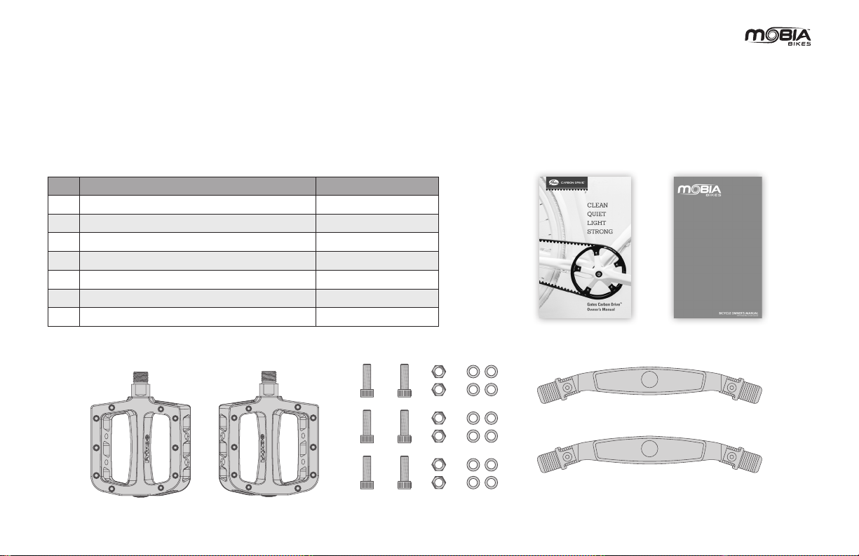
Tools and materials required:
• 4, 5, and 6mm Allen Keys
• Adjustable crescent wrench

4
BICYCLE ASSEMBLY STEPS:
1. Open shipping box and remove bicycle.
2. Extend the dual leg kickstand after unboxing to keep the bicycle upright and stable during further assembly.

5
CR-L CR-R
3. Remove the small box found at the bottom of the bicycle shipping box containing additional parts.
Included in this small box
Ref.# Description Notes
1Mobia Owner’s Manual
2 Gates Carbon Drive Owner’s Manual
3 Pedals- 1 set marked right and left on axle
4Wheel reectors- 1 set, amber color assembly depends on country
regulations
5 (6) M6X18mm bolts for front basket assembly
6(12) 6mm at washers for front basket assembly
7 (6) 6mm lock nuts for front basket assembly
FRONT BASKET ASSEMBLY
WHEEL REFLECTORS
*Design and specications are subject to change without notice.
PEDALS
GATES CARBON
DRIVE OWNER'S MANUAL
MOBIA OWNER'S MANUAL

6
M6X18
4. Remove all packaging around the front stem.
5. Loosen the two M6X18 rear stem bolts by turning them in a counter-clockwise direction, but do not fully remove them.
6. Rotate the stem 180º forward to align with the front wheel.
HOW TO INSTALL HANDLEBAR/FRONT BASKET

7
.Remove the stem clamp bolts
7. Remove the four M5X22 stem clamp bolts by turning the bolts in a counter-clockwise direction as well as the front stem cap.
8. Position handlebar into the front stem clamp.
• Center the handlebar (right to left) with the stem clamp.

8
9. Rotate the handlebar to the desired comfort angle for the wrist and arm positions.

9
1
2
3
4
10. Reinstall the four M5X22 stem clamp bolts by turning the bolts in a clockwise direction to 44.2 in-lbf (5 Nm) using a torque wrench.
• Note: Use a torque wrench to tighten bolts at this time (tightening sequence 1->2->3->4)

10
M5X15
M5X15
11. Slightly loosen the two M5X15 bolts bolts attaching the basket support bars to the front fork dropouts bolts by turning the bolts in a
counter-clockwise direction. Rotate the two basket support bars forward so the upper bolt holes are level with the ground.

11
Preinstalled support bracket
M6X18
Bolts
.Support brackets assembled on the
inside of the basket mounts
12. Unbox the front basket and assemble onto the preinstalled support bracket near the front of the fork. Install the two M6X18 bolts, washers and
locknuts provided by turning the bolts by hand in a clockwise direction. (Final tightening will happen in the following steps)
• Note : The fork support bracket mounting holes should be positioned on the inside of the basket mounting holes on the underside of the basket.

12
.Torque to 6-8 Nm
13. Assemble the support bars to the underside of the basket mount area using four M6X18 bolts by turning the bolts in a clockwise direction to
53–70 in-lbf (6-8 Nm) using a torque wrench.

13
.Torque to 6-8 Nm
14. Check to make sure the basket is level. If not, adjust by sliding the basket forward or rearward until level. Tighten the two M6X18 bolts at the
bottom of the basket by turning the bolts in a clockwise direction to 53–70 in-lbf (6-8 Nm) using a torque wrench.

14
M5X15
M5X15
.Torque to 5-7 Nm .Torque to 5-7 Nm
15. Tighten the two M5X15 bolts attaching the basket support bars to the front fork dropouts bolts by turning the bolts in a clockwise direction to
44–61 in-lbf (5-7 Nm) using a torque wrench.

15
16. Align the stem/front basket/handlebar with the front wheel.
17. After insuring that the basket is properly aligned with the front wheel tighten the two M6X18 rear stem clamp bolts by turning the bolts in a
clockwise direction using a torque wrench to 53.1 in-lbf (6 Nm), alternate tightening of bolts.
.Torque to 6 Nm .Torque to 6 Nm

16
CR-L
CR-R
CR-R
.Torque to 34.3 Nm
CR-L
.Torque to 34.3 Nm
LITHIUM GREASE
LITHIUM GREASE
18. Remove packaging on crank arms.
19. Install the right and left pedals. Please note each pedal is marked with an “R” or “L” on the axle at area. The right pedal goes on the right side
of the bike or the side where the belt or chain drive is located and the left pedal on the opposite side. Apply a small amount of lithium grease to
both pedal threads before assembly to the crank arm.
• Note : The right (drive side) pedal turns clockwise and the left (non-drive side) pedal turns counter-clockwise. Tighten using a torque wrench to 304 in-lbf (34.3 Nm).

17
20. Remove any remaining packaging on the bicycle.
21. Recheck all fasteners for tightness (according to the torque specication chart found at www.mobiabikes.com/support) and that no parts are
rubbing against the wheels or drive train.
22. Test ride the bike in an area with no trafc or other obstacles and make sure both brakes and shifting work, that tires are properly working
and that the seat is at the right height for the intended user. Also while riding make sure that the bike does not make any rubbing or other odd
sounds.

18
MOBIA BIKES WORLDWIDE LIMITED WARRANTY
1. Mobia Bikes (hereinafter “Mobia”, “our”, “we” or “us”) warrants to the original purchaser ("you") that the Mobia product for which you received
this warranty is free from defects in material and workmanship for the time frames set forth below from the date of original purchase.
2. Please see the current full warranty policy at www.mobiabikes.com/warranty for additional details.
Mobia bike frame
Mobia Fork
All originally supplied parts on the
Mobia Bike
To see our complete warranty policy, use the following web link : www.mobiabikes.com/support
Year 1 Year 2 Year 3 Year 4 Year 5

WWW.MOBIABIKES.COM
©2018 Mobia Bikes
This manual suits for next models
1
Table of contents
Other MOBIA BIKES Bicycle manuals