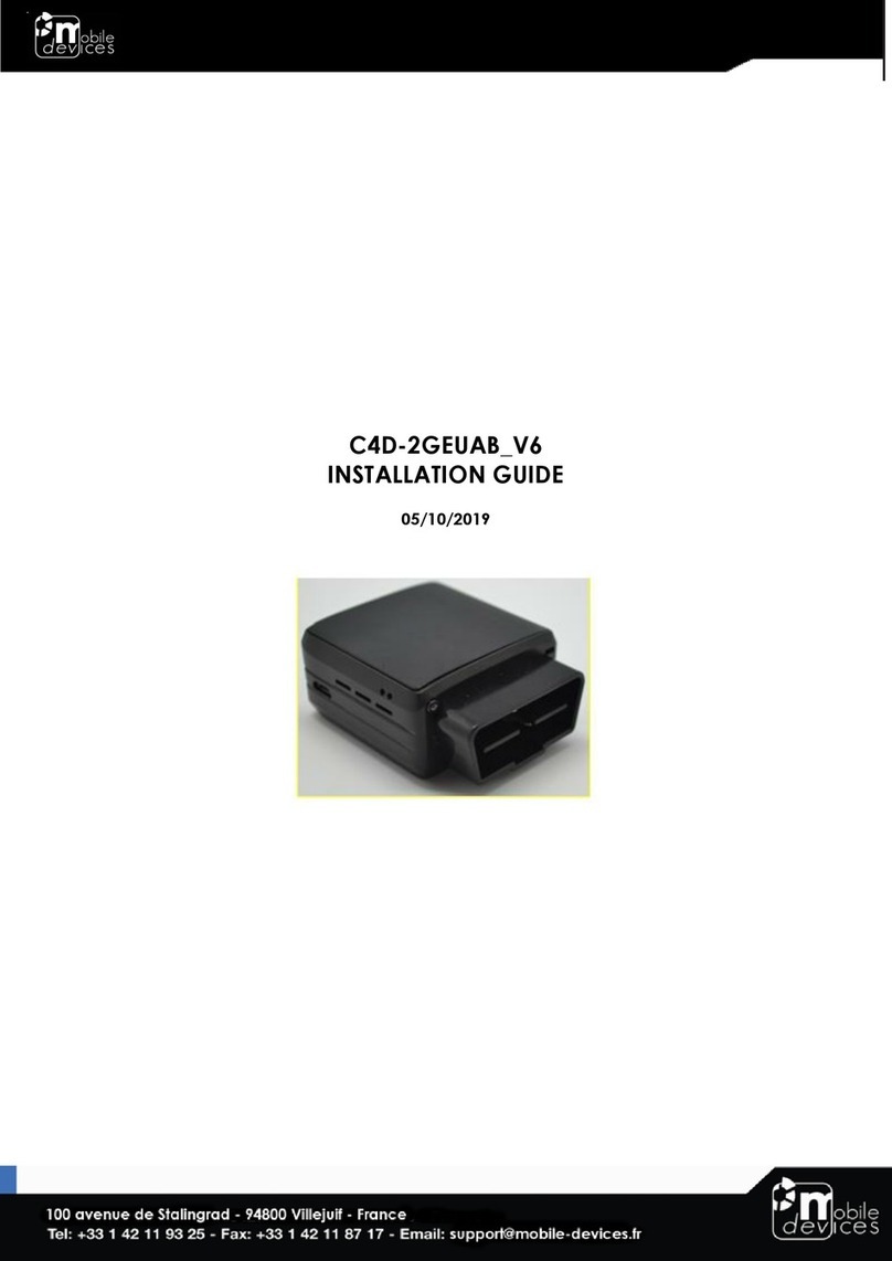
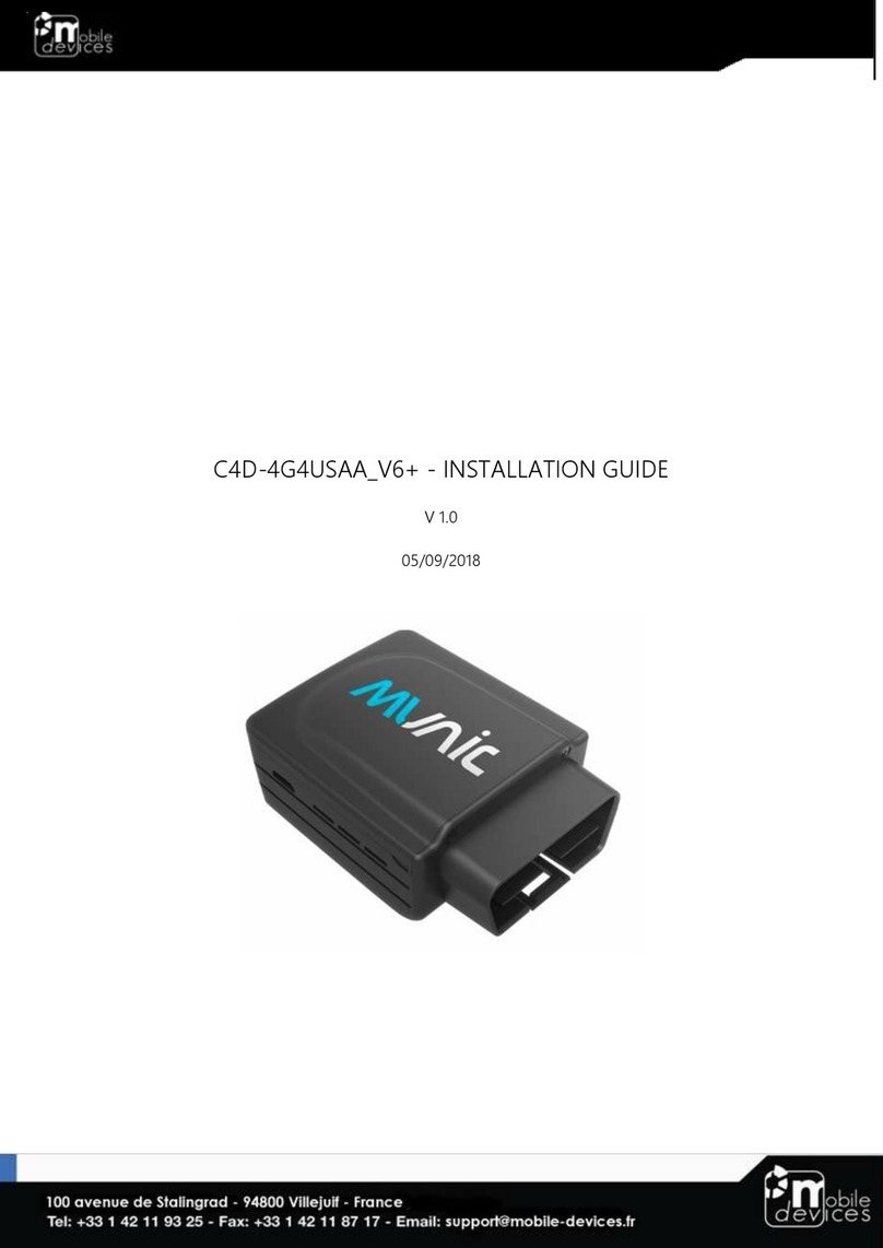
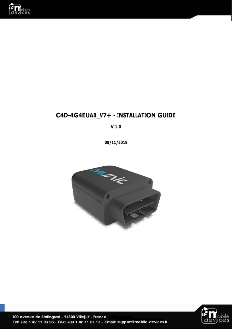
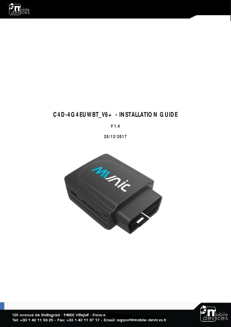
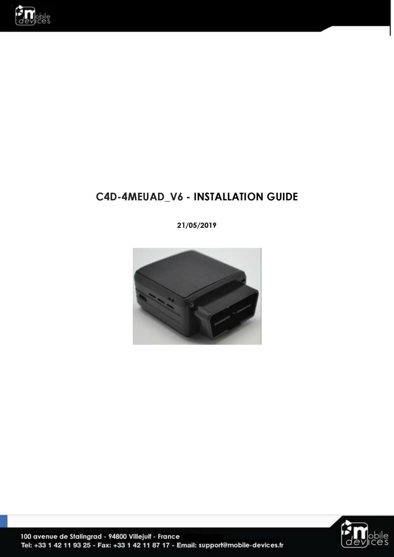
Mobile Devices C4D-4G4EUAA V6+ User manual

C4D-4G4EUAA_V6+ - INSTALLATION GUIDE
V 2.0
30/12/2020

Table of contents
Preface...................................................................................................................... 3
Warnings and notices .............................................................................................. 3
RF Exposure Information (SAR) ................................................................................ 3
1. Hardware features ............................................................................................... 4
2. Hardware description .......................................................................................... 6
2.1. External view .................................................................................................. 6
2.2. Internal view................................................................................................................6
2.3 OBD connector pin out ............................................................................................7
* Please read warnings section at the beginning of the installation guide.........7
2.4 OBD adapter wires.....................................................................................................7
3. Preparing/installing the device ....................................................................................8
3.1. Open the device.......................................................................................................8
3.2. Insert/remove the SIM card....................................................................................9
Once inserted the SIM card looks like this: ................................................................9
3.3. Properly close the device...................................................................................10
3.3. Install the OBD Dongle...........................................................................................12
4. LED sequences ................................................................................................................12
5. Support ..............................................................................................................................12

Preface
The information contained in this installation guide is subject to changes in order to improve
the reliability, design or features without prior notice. Mobile Devices Ingénierie reserves the
right to make changes in the content without obligation to notify any person or organisation
of such changes or improvements. Mobile Devices Ingénierie can in no event be held liable
for technical or editorial errors or omissions herein, nor for incidental, special or consequential
damages from the furnishing, performance or use of this installation guide.
Please contact our technical support for current updates and supplemental information
concerning the use and operation of this or other Mobile Devices Ingénierie products.
Warnings and notices
The exclamation point within an equilateral triangle is intended to alert the user
to the presence of important operating and maintenance (servicing)
instructions in the literature accompanying the product.
Please read the installation guidelines, as well as the safety and operating instructions before
operating your device. Follow all instructions and heed all warnings in the installation guide.
There is a risk of explosion if the battery is replaced by a battery with an incorrect type that
can defeat a safeguard (for example, in the case of some lithium battery types). There is also
a risk if the battery is disposed into fire or a hot oven, or mechanically crushing or cutting.
Please discard empty battery according to local regulations.
There is a risk of explosion or the leakage of flammable liquid or gas if the battery is left in a
high temperature surrounding environment or subjected to extremely low air pressure.
There is a risk with a battery subjected to extremely low air pressure that may result in
an explosion or the leakage of flammable liquid or gas
Hereby, Mobile Devices Ingénierie declares that the radio equipment type C4D-
4G4EUAA_V6+ is in compliance with Directive 2014/53/EU. The full text of the EU declaration of
conformity is available at the following internet address: http://www.mobile-devices.com/
The device could be used with a separation distance of 0.5cm to the human body. Users
have to adopt a holster/sleeve/cover without any metal components to maintain this
distance.
Dispose of used batteries according to the instructions.
RF Exposure Information (SAR)
For this device, the highest reported SAR value for usage near the body is 1.670 W/kg.
According to REDCA Technical Guidance on the publication with a restriction in the Official
Journal of Europe of the reference of standard EN 50566:2017, ensuring the safe a separation
distance of 5mm or less is applied for handled device and body-mounted wireless
communication device used by the general public, the 5mm distance is used for SAR testing
and this device is compliance with Specific Absorption Rate (SAR) for general population/
uncontrolled exposure (Localized 10-gram SAR for head and trunk, limit : 2.0W/kg) specified in
Council Recommendation 1999/519/EC, and ICNIRP Guidelines, and RED (Directive
2014/53/EU), and had been tested in accordance with the measurement methods and
procedures specified in EN50566:2017, EN62311:2008 and EN62209-2:2010

1. Hardware features
OBD Dongle
Performance
Processor
Cortex A5 - 500MHz
RAM
128 Mbytes
NAND Flash
256 Mbytes
Power supply
External power supply
range
8-18V
External voltage
measurement
-
Li-pol battery
270mA.h
Communication
Modem
4G Cat.4 Europe module (LE910-EU
V2)
Modem antenna
Internal
WLAN
Wifi
WiFi 802.11 b/g/n 2.4G
Bluetooth
BT 4.1 LE
Positioning
GNSS receiver
U-blox M8 (GPS, GLONASS)
GNSS antenna
Internal
Interface & Telematics
features
USB (2.0 Host)
powered (100mA on 5V minimum)
when connected to external power
3D Accelerometer
±2g, ±4g, ±6g, ±8g, ±16g
3 axis Gyroscope
Optional, ±250°/s, ±500°/s, ±1000°/s,
±2000°/s
OBD protocols
SAE J1850 PWM, SAE J1850 VPW, ISO
9141, ISO 14230 KWP2000, ISO 15765-4
11 bits, ISO 15765-4 29 bits, CAN
CAN interface
Simultaneous dual CAN coprocessor
Advanced vehicle
protocol supports
J2819, ISO14229, J2411,
ISO15765 ,J1939 ...
Environmental
Connectors
OBD connector
Mini USB
Operating temperature
-20°C/+55°C with Battery
-20°C/+60°C without battery
Dimensions
With OBD connector: 27x69,5x51 mm
Without OBD connector: 27x56.5x51
mm
SIM card
slot

Below value is the real value tested on conductive power, we kept sample at Lab. for trace.
Mobile (UE) –GSM
Band
Power Class
Power
(dBm)
E-GSM 900
4
32.70
DCS 1800
1
28.67
Mobile (UE) - UMTS
Band I
3
22.14
Band VIII
3
23.1
Mobile (UE) - LTE
FDD 1: Japan, Korea, Europe
21.85
FDD 3: Europe, Asia, Taiwan
22.28
FDD 7: Europe, Taiwan
22.7
FDD 8: Europe, Taiwan
22.67
FDD 20: Europe
22.69
WLAN
Bluetooth
9.5
WIFI 802.11b
WIFI 802.11g
WIFI 802.11n HT20
14.5
13
13.2

2. Hardware description
2.1. External view
2.2. Internal view
1 : OBD connector
2 : USB connector
3 : Status led
4 : GNSS antenna
5 : SIM holder
6 : Internal battery*
1
2
2
3
4
5
6
* Please read warnings section at the beginning of the installation guide

2.3 OBD connector pin out
Pin #
Comment
2
J1850+ (PWM/VPW)
4
Chassis ground
5
Signal ground
6
CAN High
7
K line
10
J1850- (PWM)
14
CAN low
15
L line
16
Battery voltage
* Please read warnings section at the beginning of the installation guide
2.4 OBD adapter wires
This adapter is only used to connect the OBD to a computer (laptop/desktop).
Pin #
Wire color
2
Yellow
4
Black
5
Grey
6
Green
7
Blue
10
Violet
14
Orange
15
White
16
Red

3. Preparing/installing the device
3.1. Open the device

3.2. Insert/remove the SIM card
The SIM card slot is located between the two electronic cards.
Once inserted the SIM card looks like this:
Insert the card with contact on
bottom into the slot and push it as far
as it will go.

3.3. Properly close the device
First, check that the electronic card is correctly inserted in the plastic part and that usb port is
correctly positioned into the casing.
If it’s not inserted proceed as shown below.
GOOD
NOT GOOD
GOOD
NOT GOOD

Second, insert the back cover beginning with the bottom.
Third, insert the top cover beginning with the back and push on top to clip-on the top cover
Finally, place the screw.

3.3. Install the OBD Dongle
Connect the OBD Dongle on your vehicle OBD connector.
4. LED sequences
The Dongle has a two-coloured LED, green and red.
When both colours are brightened, you can see an orange light.
Green LED
Red LED
Sequence
Meaning
Sequence
Meaning
Dongle OFF
OFF
No Modem
/No GNSS
3 times (50ms ON/100ms OFF)
3550ms OFF
Ext. Power/Run
ON
No Modem
/Fix GNSS
2 times (50ms ON/100ms OFF)
3700ms OFF
Modem OK
/No GNSS
1 time (50ms ON/100ms OFF)
3850ms OFF
Modem OK
/Fix GNSS
2000ms ON
2000ms OFF
Shutdown/Hibern
ate
30ms ON / 1 s OFF
Idle/Sleep
30ms ON / 1 s OFF
5. Support
For all questions not related in this installation guide, please contact the support team by
Table of contents
Other Mobile Devices Computer Hardware manuals