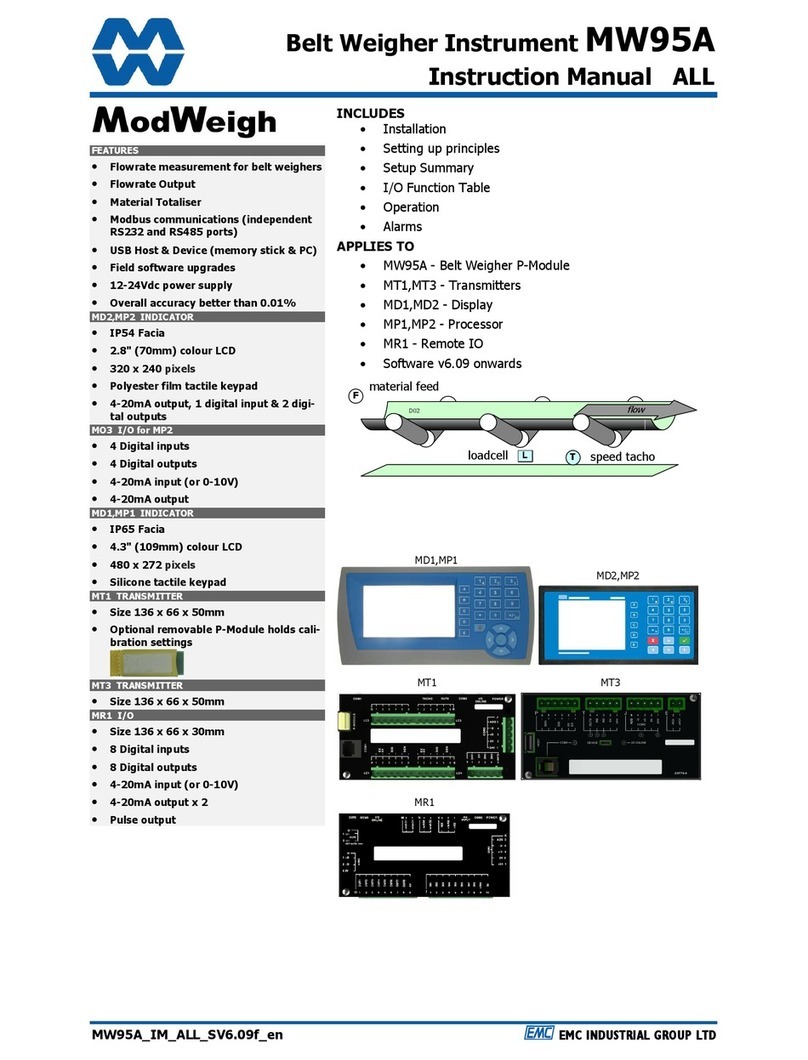
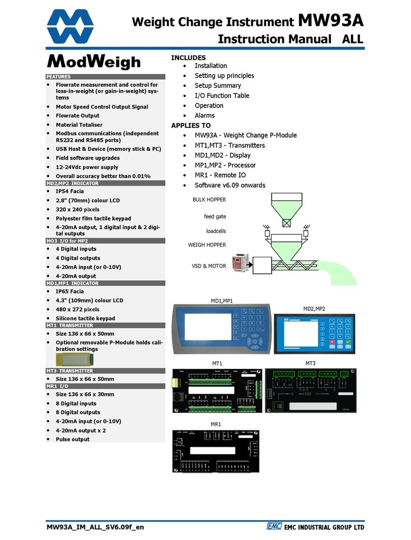
ModWeigh MW94A User manual

Impact Flowmeter Instrument MW94A
Instruction Manual ALL
MW94A_IM_ALL_SV6.09f_en EMC INDUSTRIAL GROUP LTD
FEA URES
• Flowrate measurement for impact
weighers
• Flowrate Output
• Material otaliser
• Modbus communications (independent
RS232 and RS485 ports)
• USB Host & Device (memory stick & PC)
• Field software upgrades
• 12-24Vdc power supply
• Overall accuracy better than 0.01%
MD2,MP2 INDICA OR
• IP54 Facia
• 2.8" (70mm) colour LCD
• 320 x 240 pixels
• Polyester film tactile keypad
• 4-20mA output, 1 digital input & 2 digi-
tal outputs
MO3 I/O for MP2
• 4 Digital inputs
• 4 Digital outputs
• 4-20mA input (or 0-10V)
• 4-20mA output
MD1,MP1 INDICA OR
• IP65 Facia
• 4.3" (109mm) colour LCD
• 480 x 272 pixels
• Silicone tactile keypad
M 1 RANSMI ER
• Size 136 x 66 x 50mm
• Optional removable P-Module holds cali-
bration settings
M 3 RANSMI ER
• Size 136 x 66 x 50mm
MR1 I/O
• Size 136 x 66 x 30mm
• 8 Digital inputs
• 8 Digital outputs
• 4-20mA input (or 0-10V)
• 4-20mA output x 2
• Pulse output
INCLUDES
• Installation
• Setting up principles
• Setup Summary
• I/O Function Table
• Operation
• Alarms
APPLIES O
• MW94A - Impact Flowmeter P-Mo ule
• MT1,MT3 - Transmitters
• MD1,MD2 - Display
• MP1,MP2 - Processor
• MR1 - Remote IO
• Software v6.09 onwar s
MR1
MT3
MT1
MD2,MP2
MD1,MP1

EMC INDUS RIAL GROUP L D Features
MW94A_IM_ALL_SV6.09f_en 2/53
AVAILABLE DOCUMEN A ION
COPYRIGHT © 2021 by EMC In ustrial Group Lt
56 Tarn ale Grove, Albany, North Shore, Aucklan 0632
PO Box 101 444 North Shore, Aucklan 0745, New Zealan
Telephone +64-9-415 5110, Facsimile +64-9-415 5115
E-mail sales@emc.co.nz Web http://www.emc.co.nz
As we are continuously improving our pro ucts, changes to this specification may occur without notice.
(Document Details: g0 g1 g2 g3 g4 g5 g6 g7 g8 g9 g10 g11 g12 g13 g14 g15 MT1,MT3,MD1,MD2,MP1,MP2))
PRODUC DESCRIP ION DOCUMEN A ION
MW61 Weigher Instrument Technical Information
Instruction Manual
MW64 Batch Weigher Instrument Technical Information
Instruction Manual
MW65 Process Weigher Instrument Technical Information
Instruction Manual
MW93 Weight Change Instrument Technical Information
Instruction Manual
MW94 Impact Flowmeter Instrument Technical Information
Instruction Manual
MW95 Belt Weigher Instrument Technical Information
Instruction Manual
MW96 Weighfee er Instrument Technical Information
Instruction Manual

EMC INDUS RIAL GROUP L D Features
MW94A_IM_ALL_SV6.09f_en 3/53
Contents
IN RODUC ION ....................................................... 5
Features 5
Basic 5
Inputs 5
Internal Signals 5
Outputs 5
Communications & Display 6
IO Summary 6
Specifications 7
Loa cell Input AI1 7
Analog Input AI2 7
Analog Outputs AO1 & AO2 7
Pulse Input IN0 - frequency input 7
Digital Inputs INx (except IN0) 7
Pulse Output OUT0 7
Digital Outputs OUTx (except OUT0) 8
Communications COM1, COM2 & COM3 8
General 8
INS ALLA ION ......................................................... 8
Dimensions 8
MD2 Display 8
MP2 Processor 8
MD1 Display 8
MP1 Processor 8
MT1 Transmitter 9
MT3 Transmitter 9
MR1 Remote IO 9
Connections 9
Motor integration 9
Batch Weighing 10
Run/Stop/Pause Logic 11
Connection Principles 11
Connection Diagram – MP2 12
Connection Diagram – MP1 13
Connection Diagram – MT1 14
Connection Diagram – MT3 15
Loa cell Connections 15
Tacho Connections 16
Multi rop Systems 16
SE ING UP ........................................................... 17
Setup 17
Description 17
Keypa 19
Displaying the Setup Menus 19
Selecting a Menu Item 19
Description of Menus 20
To A just A Setting 20
Macros 21
Macro Co es 21
A justing a Macro 24
Software Up ating 25
Up ate with USB Drive 25
Up ate with a PC 26
SE ING UP GUIDE................................................. 26
Settings 26
Quick Keys 26
Quick Keys Reference 26
Initial Setup 27
Engineering Units 27
Measuring Range 27
Display Resolution 27
Main Calibration 27
SE UP – MW94A IMPAC WEIGHER ........................ 28
Basic Settings 28
Engineering units 28
Measuring range 28
Display resolution 28
Tra e setup 28
Clock 28
Inputs 29
Digital inputs 29
Tacho input 29
Loa cell input (impact weight) 29
Calibrate loa cell 30
Calibrate Using Loa cell Specifications 30
Current/Voltage input 31
Internal Signals 32
Weight 32
Flowrate 33
Totaliser 33
Limits 33
Events/Alarms/Faults 34
Memory Storage 34
User ata 35
Outputs 36
Analog output 1 (flowrate) 36
Analog output 2 (weight) 36
Digital outputs 37
Communications & Display 37
Comms port 1 - RS232 37
Comms port 2 - RS485 37
Comms port 3 - RS485 MR1 38
Interface registers 38
Printing & Macros 38
Display (MD1,MD2,MP1,MP2) 40
USB 43
Info, Resets & Final Cal 43
Pro uct Information 43
Reset settings 44
Reset macros 44
Final calibration 44
SE UP – DISPLAY ................................................... 44
Basic Settings 44
Clock 44
Communications & Display 45

EMC INDUS RIAL GROUP L D Features
MW94A_IM_ALL_SV6.09f_en 4/53
Comms port 1 – RS232 45
Comms port 2 – RS485 45
Display 45
CompactCom 46
Information & Resets 46
Pro uct Information 46
Reset settings 46
Other display settings 46
I/O Function able 46
OPERA ING DE AILS.............................................. 49
Mo bus Access 49
OPERA ION ............................................................ 49
Display 49
Keys 50
Operator Menu 50
Actions 51
Settings 52
Alarm menu 52

EMC INDUS RIAL GROUP L D Features
MW94A_IM_ALL_SV6.09f_en 5/53
IN RODUC ION
Features
Basic
Units & Resolution
The units for each variable type (weight etc.) can be selecte from a list of metric an imperial units.
The resolution of each variable type can be a juste , this alters the count by e.g 100kg isplaye in
0.2kg increments.
OIML Design
The instrument is esigne to OIML stan ar s.
Language Support
Support is available for the following languages: English, Chinese, Korean, German, Spanish, French,
Italian an Polish.
Inputs
Digital Inputs INx
The igital inputs are programmable to a range of function inclu ing ‘acquire zero’, ‘print’ etc.
Corner Adjustment (M 1 only)
The input sensitivity can be in ivi ually a juste for up to 4 loa cells, allowing ifferences in loa cell
sensitivities to be correcte .
Four Loadcell Inputs (M 1 only)
Separate inputs are available for 4 loa cells allowing the signal of each to be monitore sperately. This
provi e an ai for loa balancing across loa cells an also for fault fin ing.
Zeroing
Auto zeroing automatically sets the zero point when there is no material flow an re uces errors that
woul be cause by an incorrect zero.
Signal Filtering
Filtering for the weight can be a juste to get the optimum compromise between re uction of plant vi-
bration an response spee .
Internal Signals
Limits
The high an low limits have a justable setpoints which may be programme to operate on any internal
signal.
Batching
The system can be use to batch out a esire weight by stopping the fee er when the batch weight
has been totalise . A pre-act is available to compensate for overrun.
Event Collection
Process events are collecte for operation with external equipment (PLCs etc.)
Memory Storage
Allows a group of settings to be store or recalle from memory. This can be use for example to store
settings for ifferent pro ucts. There are 20 memory locations with up to 4 settings in each.
Material otal
The processor incorporates a totaliser which totalises the weight of material through the system. The
totaliser can be reset to zero. A pulse output is available to operate external counters. A low flow cutout
ensures that low flows o not cause false counts. The total is retaine after a power failure.
The totaliser can be set to operate with 5, 6, 7 or 8 igits.
Outputs
Material Flowrate
An analog flowrate output signal is available for connection to other instruments.
Analog I/O Scaling
The analog output range can be a juste over the full 0 to 20mA range. The output will rive to a slight
negative mA, allowing a live zero to be achieve when using a 0 to 20mA range. A voltage output is
easily pro uce by connecting a resistor to the output.
In a ition the analog output signal is selectable to come from any internal signal in the instrument e.g
weight, flowrate etc.
Digital Outputs OU x
The igital outputs are programmable to operate from any internal signal. These signals inclu e the
igital input states, status con itions (running, pause etc) an any fault con itions that are etecte .
This makes it easy connect into other systems.

EMC INDUS RIAL GROUP L D Features
MW94A_IM_ALL_SV6.09f_en 6/53
Communications & Display
Comms
RS232 an RS485 ports are available. These are use to connect Mo Weigh units together an also to
connect to other systems. The protocol is either ASCII output for example to rive a printer or Mo bus
for interactive communications. Bau rates an no e a resses are programmable.
USB host an evice ports are available. This allows for example PC an USB flash rive connectivity. It
can be use to up ate the units software, for ata logging an for recor ing of the units settings.
Printouts & Macros
Printouts can be triggere by a key press or set up to occur at set times uring the ay or week. Data
may also be output continuously for ata collection purposes. Data is output on the COM1 RS232 port.
The content of the printouts is fully programmable using Macros.
Macros are programs use to customise printouts, but can also be use to perform arithmetic calcula-
tions. The Macro language also contains con itional terms for more a vance programming.
Display Customisation
Locks may be set to prevent unauthorise use of the operator keys an restrict entry to the operator
menu. The keys are in ivi ually lockable an optionally a passco e can be use to allow authorise op-
erators to use the keys. Alternatively a confirmation of the key action can be requeste .The operator
MENU can be customise to make a itional settings or signals available to the operator.
The contents of the main isplay can be set to suit any con ition, from a comprehensive isplay show-
ing all operating parameters to a simple isplay showing the basic signals.
Computer Connectivity
Mo Weigh instruments can be connecte to a computer withan RS232 connection. Data can be sent to
the PC at a preset rate. The ata sent can be set up using macros.
There is also a comman line interface which allows any of the settings an ata to be rea or written.
IO Summary
Digital Inputs
(inclu es pulse input)
NAMUR pulse input option
Digital Outputs
(inclu es pulse output)
Isolate Pulse Output
Isolate 4-20mA Inputs
Isolate 4-20mA Outputs
RS232
RS485
USB Host (Memory Stick)
USB Device (PC Cable)
Corner a justment an bal-
ancing for 4 loa cells
Tra e approvals (MW95,
MW96)
MP2 1 2 1 0 1 1 1 1 1
MP2,MO3 1+4 2+4 1 1 1+1 1 1 1 1
MP1,MR1 1+8 9 1 1 2 2 1 1 1
MD1,MT1,MR1 2+8 1+9 1 1 2 2 2 1 1
MD2,MT1,MR1 2+8 1+9 1 1 2 2 2 1 1
MD1,MT3 2 1 0 0 1 2 1 1 1
MD2,MT3 2 1 0 0 1 2 1 1 1
MD1,MT3,MR1 2+8 8 1 1 3 2 1 1 1
MD2,MT3,MR1 2+8 8 1 1 3 2 1 1 1

EMC INDUS RIAL GROUP L D Specifications
MW94A_IM_ALL_SV6.09f_en 7/53
Specifications
Loadcell Input AI1
Input Range ±4 mV/V (0-20mV)
Excitation 5 V c ±20 %, 250 mA maximum current
Signal processing rate 100 Hz (response time setting≤ 0.5 s)
Input sensitivity 0.5 µV/ ivision maximum
Zero range ±3 mV/V (±15 mV)
Zero rift ±0.02 µV+0.0005 % of ea loa /°C typical
Span rift ±0.0005 %/°C typical
Non-linearity ‹0.002 % of FS
Input noise 0.15 µVp-p typical
Filtering 0.04 s to 32.0 s response time a justable
Sense voltage range 1-5 V
Analog Input AI2
4-20mA input resistance <60 Ω
0-10V input resistance ›100 kΩ
Isolation galvanically isolate to 50Vac
Analog Outputs AO1 & AO2
Output range 0 to 20 mA (-0.2 mA to 21 mA, inclu es stan ar 4-20mA)
Maximum loa 1000Ω
Resolution 0.4 µA
Response time Loa cell response time setting + 20 ms
Voltage output Use an external resistor to convert mA to volts.
For example 500Ω gives 10 V at 20 mA.
Non-linearity ‹0.01 %
Drift ‹2 µA/°C.
Isolation in epen ently galvanically isolate to 50Vac
Pulse Input IN0 - frequency input
Maximum range 0.01Hz to 4 kHz
Typical operating range 10 to 1000 Hz
Minimum pulse wi th 50us
IN0 set to PNP
High voltage › 8 V
Low voltage ‹ 4 V
Maximum voltage 32 V
Input loa 4 kΩ approximate
IN0 set to NAMUR
Terminal voltage 8 V
Switching threshol 1.55 mA
Hysteresis 0.2 mA
Namur fault ‹0.1 mA or ›6 mA
IN0 set to AC
Voltage range 0.2 to 50 Vac
Digital Inputs INx (except IN0)
High voltage › 8 V
Low voltage ‹ 4 V
Maximum voltage 32 V
Input loa 6 kΩapproximate
Input type PNP output sensors
Pulse Output OU 0
Max output current 50 mA
Max working voltage 30V ac/ c
Max frequency 500 Hz
Duty cycle 50 % ±20 % (f › 0.5 Hz)
Max output pulse time 1000 ms (f ‹ 0.5 Hz)
Isolation galvanically isolate to 50 Vac

EMC INDUS RIAL GROUP L D Dimensions
MW94A_IM_ALL_SV6.09f_en 8/53
Digital Outputs OU x (except OU 0)
Max output current Σ IIOx < 0.25 A
Output voltage same as supply voltage
Communications COM1, COM2 & COM3
COM1 Interface RS232
COM1 Han shake CTS can be enable
COM2/COM3 Interface RS485
Bau rates 9600, 19200, 38400, 57600, 115200 (230400 on COM2)
Settings 8 ata bits, no parity, 2 stop bits (8-N-2)
Protocol Mo bus RTU (MWBUS on COM2)
General
IP Rating IP20 (MD1,MP1 facia IP65) (MD2,MP2 facia IP54)
Operating temperature -10 to 45 °C
Supply voltage 10 to 28 V c
Power MT1 1.0 to 2.2 W + PTacho Excitation
Power MT3 1.0 to 2.2 W + PTacho Excitation
Power MR1 1.5 to 2.5 W + POUTx
Power MD1 1.8 W
Power MP1 1.8 to 3.0 W
Power MD2 1.4 W
Power MP2 1.4 to 3.1 W
Power MP2 + MO3 3.4 to 5.0 W + POUTx + PTacho Excitation
MP2 Restrictions PLoa cell Excitation + PAO1 + PAO2 < 1.5 W
ISupply < 0.5 A
INS ALLA ION
The instrumentation must be mechanically installe an then the electrical connections ma e. The im-
portant electrical connections are as follows.
Power supply connections: 24V c fuse or current limite to 5A.
Communications: A shiel e cable is recommen e to connect units together with COM2. It can exten
up to 500m. This leaves COM1 (RS232) free for other applications. For a cable length over 50m, MAT
line terminators must be fitte at each en of the cable.
Loa cell connections: For cable runs less than 20m, a 4 wire connection shoul be a equate. For longer
cable lengths, a 6 wire connection is recommen e .
Some a itional optional connections are as follows.
A remote totaliser.
The 4-20mA measure flowrate output.
Dimensions
Following are the imensions of the har ware items that make up the system.
The isplays/processors are esigne for panel mounting.
MD2 Display
MP2 Processor
MD1 Display
MP1 Processor
PANEL cut out
186 x 92 mm
-0.0 + 1.0 mm
FACIA
208 x 104 mm
top view
approx. 450g
104mm
30mm
8mm
208mm
PANEL cut out
138 x 67 mm
-0.0 + 1.0 mm
FACIA
144 x 72 mm
top view
approx. 400g
72mm
80mm
9mm
144mm

EMC INDUS RIAL GROUP L D Connections
MW94A_IM_ALL_SV6.09f_en 9/53
M 1 ransmitter
M 3 ransmitter
MR1 Remote IO
Connections
Motor integration
The following iagrams show various metho s to connect a Mo Weigh to a VSD rive or motor contac-
tor.
VSD Drive, keypad run/stop
Mo Weigh keypa use to start an stop the system. Can be use for batching applications.
VSD Drive, VSD run/stop
Mo Weigh slave from VSD running signal.
• isable START key
• o not use start function
VSD drive, start/stop buttons
External START / STOP buttons connecte to Mo Weigh instrument riving motor VSD.
Motor Contactor, keypad run/stop
Mo Weigh keypa use to start an stop system. Contactor use to run motor.
VSD run input
run motor [OU 3, 56]
+24V 0V
NO stop [INx, -1]
VSD OK
start [INx, 27]
START
STOP
run [IN3,2]
VSD running signal
+24V 0V
VSD run input
run motor [OU 3, 56]
+24V 0V
NO stop [INx, -1]
VSD OK
136mm
66mm
20mm
8mm
optional DIN rail mount
approx. 350g
156mm
86mm
136mm
66mm
20mm
50mm
8mm
optional DIN rail mount
approx. 35
0g
136mm
66mm
20mm
50mm
8mm
optional DIN rail mount
approx. 350g

EMC INDUS RIAL GROUP L D Connections
MW94A_IM_ALL_SV6.09f_en 10/53
Motor Contactor, run/stop buttons
External START / STOP buttons connecte to Mo Weigh instrument controlling motor contactor.
• isable START key
• o not use start function
Batch Weighing
External Buttons for Batching – Method 1
When START is presse , the total is reset an the motor starte . Pressing STOP at anytime stops the
motor. If CONTINUE is presse with the total weight below the batch weight, the motor will start with-
out resetting the total.
• isable START key
External Buttons for Batching – Method 2
Pressing START resets the total an starts the motor. Pressing PAUSE stops the motor. If pause , the
batch may be continue by pressing START. Pressing STOP stops the motor an aborts the batch.
• isable START key
External Buttons for Batching – Method 3
Pressing START will reset the total an start the motor. If running, pressing PAUSE/STOP will stop the
motor an pause. Pressing PAUSE/STOP a secon time will cancel the pause an abort the batch. Press-
ing START when the controller is pause will start the motor without resetting the total.
pause [INx, 30]
motor contactor (mc)
0V
run motor [OU 3, 56]
+24V
START
batch start [INx, 29]
PAUSE
STOP
NO stop [INx, -1]
motor contactor (mc)
0V
run motor [OU 3, 56]
+24V
START
batch start [INx, 29]
CONTINUE
start [INx, 27]
STOP
NO stop [INx, -1]
+24V 0V
mc
START
run [IN3, 2]
STOP
motor contactor (mc)
overloa
mc
motor contactor
run motor
[OU 3, 56]
+24V 0V
NO stop [INx, -1]
overloa
overloa

EMC INDUS RIAL GROUP L D Connections
MW94A_IM_ALL_SV6.09f_en 11/53
• isable START key
Key
Run/Stop/Pause Logic
The following table escribes how the status is affecte by the inputs.
Inputs (Control1) Outputs (Status1)
stop run pause start running pause run motor
1 X X X 0 0 0
0 1 0 X 1 0 1
0 0 0 0 * 0 0 0
0 X 1 X NC 1 0
0 0 0 1 0 1
0 0 1 1 1 0
KEY
Entry Description
0 input or output off
1 input or output on
X on’t care (either on or off)
NC no change
rising e ge (input turns on)
* remains off since last stop
Connection Principles
Mo Weigh instruments can be configure in many ifferent ways to suit any given application.
The isplay is normally locate to suit an operator. The transmitter can be locate in the fiel to re uce
fiel wiring or can be locate with the isplay for a more conventional approach.
The I/O can conveniently be situate on a DIN rail in a cabinet.
Mo Weigh igital output
+
−
AOx
Mo Weigh igital input
Mo Weigh analog output
[OU x,
output function
]
[INx, input function]
pause/stop [INx, 31]
motor contactor (mc)
0V
run motor [OU 3, 56]
+24V
START
batch start [INx, 29]
PAUSE/STOP
paused [OU x, 58] PAUSED

EMC INDUS RIAL GROUP L D Connections
MW94A_IM_ALL_SV6.09f_en 12/53
Connection Diagram – MP2
D
1
D
2
D
3
D
4
D
5
Analog
+AO2
−
AO2
+VAI2
+mAAI2
−
AI2
pulse output
running
run motor
healthy
no function
enable flowrate
run
reset total
MP2
2
3
4
5
6
7
8
2
3
4
6
7
20
RXD
DSR
SG
DTR
CTS
RTS
RXD
TXD
CTS
DSR
SG
DTR
P1
P2
P3
P4
P5
P6
RTS
TXD
0V
0V
RXD
CTS
RJ12
Loadcell
Power/COM2
+EX
−
EX/0V
+
SIG
−
SIG
+
SEN
−
SEN
24V
0V
COM1
MAC
MAP
DB25M
t
o
Printer
flowrate
LOADCELL
(s)
optional sense for 6 wire
connection
BEL SPEED ACHO
+
0
V
output
B
1
B
2
B
3
B
4
B
5
B
6
I/O
+AO1
−
AO1
+/~ OUT0
−
/~ OUT0
OUT9
IN9
B7
0V
C
1
C
2
C
3
C
4
C
5
C
6
C
7
C
8
C
9
Digital
I/O
OUT1
OUT2
OUT3
OUT4
{MT1}
IN1
IN2
IN3
IN4
24V
C10
0V
O ALISER
input
0
V
weight
POWER SUPPLY
+24V
0
V
A1
A
2
run motor
enable flowrate
MO3 OP ION
24V
O ALISER
input
0V
I1
I2
I3
I4
I5
I6
I7
I8
I9
I10
H1
H2
H3
V1
V2
V3
K1
K2
K3
K4
K5
O1
O2
O3
O4
O5
O6
O7
O8
O9
U1
U2
M1
M2
M3
M4
Digital Inputs
Power/COM2
Digital Outputs
Pulse Output
Analog Outputs
COM3
Analog Input 2
IN1
IN2
IN3
IN4
IN5
IN6
IN7
IN8
24V
0V
24V
0V
+
D
−
D
ADS
OUT1
OUT2
OUT3
OUT4
{MT1}
OUT5
OUT6
OUT7
OUT8
0V
+mAO2
−
mAO2
+mAO1
−
mAO1
+/~ OUT0
−
/~ OUT0
+D
−
D
0V
+VI2
+mAI2
−
AI2
pulse output
running
run motor
healthy
weight fault
pause
flowrate enable
alarm alert
to
PC, PLC
or
Mo Weigh D isplay
MD1,MD2
weight
flowrate
no function
enable flowrate
run
reset total
print
print total
stop
pause
A
3
A
4
A
5
+
D
−
D
IN0
t
o PC/PLC
TXD
MAD
DB9F
MR1
Address Select ADS
1
2
3
4
5
24V
0V
+
D
−
D
ADS
1
2
3
4
5
1
2
3
4
5
1
2
3
4
5
R
1k
2k2
4k7
10k
22k
47k
100k
4
5
6
7
8
9
10
1
2
3
Keep all wiring separate
from mains wiring
Use shiel e cable where
in icate

EMC INDUS RIAL GROUP L D Connections
MW94A_IM_ALL_SV6.09f_en 13/53
Connection Diagram – MP1
O ALISER
input
0V
I1
I2
I3
I4
I5
I6
I7
I8
I9
I10
H1
H2
H3
V1
V2
V3
K1
K2
K3
K4
K5
O1
O2
O3
O4
O5
O6
O7
O8
O9
U1
U2
M1
M2
M3
M4
Digital Inputs
Power/COM2
Digital Outputs
Pulse Output
Analog Outputs
COM3
Analog Input 2
IN1
IN2
IN3
IN4
IN5
IN6
IN7
IN8
24V
0V
24V
0V
+
D
−
D
ADS
OUT1
OUT2
OUT3
OUT4
{MT1}
OUT5
OUT6
OUT7
OUT8
0V
+mAO2
−
mAO2
+mAO1
−
mAO1
+/~ OUT0
−
/~ OUT0
+D
−
D
0V
+VI2
+mAI2
−
AI2
pulse output
running
run motor
healthy
weight fault
pause
flowrate enable
alarm alert
MP1
MR1
2
3
4
6
7
20
RXD
TXD
CTS
DSR
SG
DTR
MAC
MAP
DB25M
t
o
Printer
to
PC, PLC
or
Mo Weigh D isplay
MD1,MD2
weight
flowrate
no function
enable flowrate
run
reset total
print
print total
stop
pause
LOADCELL
(s)
optional sense for 6 wire
connection
Address Select ADS
1
2
3
4
5
24V
0V
+
D
−
D
ADS
1
2
3
4
5
1
2
3
4
5
1
2
3
4
5
R
1k
2k2
4k7
10k
22k
47k
100k
4
5
6
7
8
9
10
1
2
3
BEL SPEED ACHO
+
0
V
output
POWER SUPPLY
+24V
0
V
TXD
2
3
4
5
6
7
8
RXD
DSR
SG
DTR
CTS
RTS
MAD
DB9F
t
o PC/PLC
P1
P2
P3
P4
P5
P6
A1
A
2
A
3
A
4
A
5
RTS
TXD
0V
0V
RXD
CTS
RJ12
Loadcell
Power/COM2
+EX
−
EX/0V
+
SIG
−
SIG
+
SEN
−
SEN
24V
0V
+
D
−
D
IN0
COM1
Keep all wiring separate
from mains wiring
Use shiel e cable where
in icate
MP1 bus a ress set with
setting (Q2522).
MR1 bus a ress set with
ADS pin an must be same
as MP1.
Fit an MAT terminator to
each en of COM2 cable if
length excee s 50m.

EMC INDUS RIAL GROUP L D Connections
MW94A_IM_ALL_SV6.09f_en 14/53
Connection Diagram – M 1
BEL SPEED ACHO
+
output
0
V
POWER SUPPLY
+24V
0
V
O ALISER
input
0V
I1
I2
I3
I4
I5
I6
I7
I8
I9
I10
H1
H2
H3
V1
V2
V3
K1
K2
K3
K4
K5
O1
O2
O3
O4
O5
O6
O7
O8
O9
U1
U2
M1
M2
M3
M4
Digital Inputs
Power/COM2
Digital Outputs
Pulse Output
Analog Outputs
COM3
Analog Input 2
IN1
IN2
IN3
IN4
IN5
IN6
IN7
IN8
24V
0V
24V
0V
+
D
−
D
ADS
OUT1
OUT2
OUT3
OUT4
{MT1}
OUT5
OUT6
OUT7
OUT8
0V
+mAO2
−
mAO2
+mAO1
−
mAO1
+/~ OUT0
−
/~ OUT0
+D
−
D
0V
+VI2
+mAI2
−
AI2
pulse output
running
run motor
healthy
weight fault
pause
flowrate enable
alarm alert
MD1,MD2
MT1
MR1
L1
L
2
L
3
L
4
L
5
RTS
TXD
0V
0V
RXD
CTS
RJ12
Power/COM2
24V
0V
+
D
−
D
ADS
COM1
TXD
2
3
4
5
6
7
8
2
3
4
6
7
20
RXD
DSR
SG
DTR
CTS
RTS
RXD
TXD
CTS
DSR
SG
DTR
MAC
MAD
DB9F
t
o PC/PLC
MAP
DB25M
t
o
Printer
to
PC, PLC
or
Mo Weigh D isplay
MD1,MD2
weight
flowrate
no function
enable flowrate
run
reset total
print
print total
stop
pause
LOADCELL
(s)
optional sense for 6 wire
connection
Address Select ADS
1
2
3
4
5
24V
0V
+
D
−
D
ADS
1
2
3
4
5
1
2
3
4
5
1
2
3
4
5
R
1k
2k2
4k7
10k
22k
47k
100k
4
5
6
7
8
9
10
1
2
3
P1
P2
P3
P4
P5
P6
Q1
Q2
Q3
Q4
Q5
Q6
T1
T2
T3
T4
T5
J1
J2
J
3
J
4
J
5
R1
R2
R3
R4
R5
R
6
S
1
S
2
S
3
S4
S5
S6
RTS
TXD
0V
0V
RXD
CTS
RJ1
2
Loadcell 1
Loadcell 2
acho (I/O)
Loadcell 4
Loadcell 3
Power/COM2
+EX
−
EX/0V
+
SIG
−
SIG
+
SEN
−
SEN
+EX
−
EX/0V
+
SIG
−
SIG
+
SEN
−
SEN
+EX
−
EX/0V
+
SIG
−
SIG
+
SEN
−
SEN
24V
0V
+
D
−
D
ADS
24V
0V
IN0
IN9
OUT9
+EX
−
EX/0V
+
SIG
−
SIG
+
SEN
−
SEN
COM1
enable flowrate
run motor
Keep all wiring separate
from mains wiring.
Use shiel e cable where
in icate .
For in ivi ual loa cell sensi-
tivity a justment, use termi-
nals P, Q, R an S.
Display an transmitter can
alternatively be connecte
COM1 to COM1 using an MAC
cable.
MT1 bus a ress set with
ADS pin or a setting.
MR1 bus a ress set with
ADS pin an must be same
as MT1.
Fit an MAT terminator to
each en of COM2 cable if
length excee s 50m.

EMC INDUS RIAL GROUP L D Connections
MW94A_IM_ALL_SV6.09f_en 15/53
Connection Diagram – M 3
Loadcell Connections
The loa cell(s) may be wire irectly to the loa cell terminals or connecte together in the fiel with a
junction box an connecte to the Mo Weigh unit with a single cable.
When connecte to the terminals only a 4-wire connection is use , an igital corner a justments are
possible. (MT1 only)
When connecte with one cable an a junction box no corner a justments are possible. It is preferable
to use a 6-wire connection as this eliminates voltage rop errors in long cables cause by cable resis-
tance.
BEL SPEED ACHO
+
output
0
V
POWER SUPPLY
+24V
0
V
O ALISER
input
0V
I1
I2
I3
I4
I5
I6
I7
I8
I9
I10
H1
H2
H3
V1
V2
V3
K1
K2
K3
K4
K5
O1
O2
O3
O4
O5
O6
O7
O8
O9
U1
U2
M1
M2
M3
M4
Digital Inputs
Power/COM2
Digital Outputs
Pulse Output
Analog Outputs
COM3
Analog Input 2
IN1
IN2
IN3
IN4
IN5
IN6
IN7
IN8
24V
0V
24V
0V
+
D
−
D
ADS
OUT1
OUT2
OUT3
OUT4
{MT1}
OUT5
OUT6
OUT7
OUT8
0V
+mAO2
−
mAO2
+mAO1
−
mAO1
+/~ OUT0
−
/~ OUT0
+D
−
D
0V
+VI2
+mAI2
−
AI2
pulse output
running
run motor
healthy
weight fault
pause
flowrate enable
alarm alert
M
D1,MD2
MR1
L1
L
2
L
3
L
4
L
5
RTS
TXD
0V
0V
RXD
CTS
RJ12
Power/COM2
24V
0V
+
D
−
D
ADS
COM1
TXD
2
3
4
5
6
7
8
2
3
4
6
7
20
RXD
DSR
SG
DTR
CTS
RTS
RXD
TXD
CTS
DSR
SG
DTR
MAC
MAD
DB9F
t
o PC/PLC
MAP
DB25M
t
o
Printer
to
PC, PLC
or
Mo Weigh D isplay
MD1,MD2
weight
flowrate
no function
enable flowrate
run
reset total
print
print total
stop
pause
LOADCELL
(s)
optional sense for 6 wire
connection
Address Select ADS
1
2
3
4
5
24V
0V
+
D
−
D
ADS
1
2
3
4
5
1
2
3
4
5
1
2
3
4
5
R
1k
2k2
4k7
10k
22k
47k
100k
4
5
6
7
8
9
10
1
2
3
MT3
P1
P2
P3
P4
P5
P6
E
1
E
2
T1
T2
T3
T4
T5
J1
J2
J
3
J
4
J
5
RTS
TXD
0V
0V
RXD
CTS
RJ1
2
Loadcell 1
Analog Output
acho (I/O)
Power/COM2
+EX
−
EX/0V
+
SIG
−
SIG
+
SEN
−
SEN
+AO1
−
AO1
24V
0V
+
D
−
D
ADS
24V
0V
IN0
IN9
OUT9
COM1
enable flowrate
run motor
flowrate
Keep all wiring separate
from mains wiring.
Use shiel e cable where
in icate .
Display an transmitter can
alternatively be connecte
COM1 to COM1 using an MAC
cable.
MT3 bus a ress set with
ADS pin or a setting.
MR1 bus a ress set with
ADS pin an must be same
as MT3.
Fit an MAT terminator to
each en of COM2 cable if
length excee s 50m.

EMC INDUS RIAL GROUP L D Connections
MW94A_IM_ALL_SV6.09f_en 16/53
acho Connections
A spee sensor can be connecte an use to measure an isplay the spee (RPM) of a material fee
screw. The sensor shoul give one pulse per revolution of the screw.
When the measure spee excee s 60rpm, flowrate measurement is enable .
The tacho sensor may use either a 2 wire or 3 wire connection.
3 Wire PNP or Push Pull Output 2 Wire Output
NAMUR Sensor AC Sensor
Multidrop Systems
Mo Weigh instruments can be connecte using the COM2 RS485 bus. Up to 10 systems may be con-
necte on the bus. A Mo Weigh isplay can select any one of the systems on the bus to work with.
T1
T2
T3
T4
T5
acho (I/O)
24V
0V
IN0
IN9
OUT9
BEL SPEED ACHO
−
+
T1
T2
T3
T4
T5
acho (I/O)
24V
0V
IN0
IN9
OUT9
BEL SPEED ACHO
~
~
AC
M 1
M 1,M 3
BEL SPEED ACHO
+
output
0
V
A
1
A
2
A
3
A
4
A
5
acho (I/O)
24V
0V
+D
‒
D
IN0
A
1
A
2
A
3
A
4
A
5
24V
0V
+D
‒
D
IN0
BEL SPEED ACHO
+
−
acho (I/O)
MP1,MP2
MP1,MP2
BEL SPEED ACHO
+
output
0
V
T1
T2
T3
T4
T5
acho (I/O)
24V
0V
IN0
IN9
OUT9
T1
T2
T3
T4
T5
24V
0V
IN0
IN9
OUT9
BEL SPEED ACHO
+
−
acho (I/O)
M 1 ,M 3
Q1
Q2
Q3
Q4
Q5
Q6
Loadcell 2
+EX
−
EX/0V
+
SIG
−
SIG
+
SEN
−
SEN
P1
P2
P3
P4
P5
P6
Loadcell 1
+EX
−
EX/0V
+
SIG
−
SIG
+
SEN
−
SEN
R
1
R
2
R
3
R
4
R
5
R
6
Loadcell 3
+EX
−
EX/0V
+
SIG
−
SIG
+
SEN
−
SEN
S
1
S
2
S
3
S
4
S
5
S
6
Loadcell 4
+EX
−
EX/0V
+
SIG
−
SIG
+
SEN
−
SEN
4
3
2
1
Loa cells Wire to
Directly to Terminals
Allows corner a justment an in ivi ual
monitoring of loa cell outputs
M 1
P1
P2
P3
P4
P5
P6
Loadcell 1
+EX
−
EX/0V
+
SIG
−
SIG
+
SEN
−
SEN
LOADCELL
(s)
optional sense for 6 wire
connection
1
+E
1
−
E
+S
−
S
2
+E
1
−
E
+S
−
S
3
+E
1
−
E
+S
−
S
4
+E
1
−
E
+S
−
S
Loa cells Wire to Junction Box
For best accuracy use a 6-wire connec-
tion to controller
M 1,M 3

EMC INDUS RIAL GROUP L D Setup
MW94A_IM_ALL_SV6.09f_en 17/53
A multi rop connection can also be use with any other Mo bus master evice such as a PLC. If a non
Mo Weigh master is use on the bus, then the Mo Weigh instruments are unable to communicate with
one another. An external Mo bus master can alternatively be connecte to an RS232 COM1 port.
An MR1 unit cannot share the bus with a non Mo Weigh master such as a PLC. A PLC coul be con-
necte using the COM3 port on the MR1.
To connect in muti rop use the RS485 connection COM2. The wiring shoul be ma e in a aisy-chain,
with one instrument connecte to the next. If a stub connection is use to a main cable as shown in the
iagram, then make sure its length limit is a here to.
Two MAT line terminators must be fitte , one at each en of the cable run.
The +D, -D an a 0V terminal must all be connecte together through the ata cable.
Setting the COM1 Modbus Address
Before a multi rop system will operate, the a resses in each of the Mo Weigh units will nee to be set
ifferently. This can be one by wiring a link or resistor to the ADS terminal where available. See the
table on the connection iagram. Alternatively the a ress setting can be change in each unit using a
isplay connecte to its COM1.
The following proce ure is use to set a units a ress.
1. Press the Q key to access the setup menu.
2. Key in the quick key co e 2512 to select the ‘COM1&2 mo bus a ress’ step.
3. Press the EDIT key. (If e iting is locke , key in the passwor 111 an press ENTER).
4. Enter the esire a ress (1, 2 or 3 etc.) an press ENTER.
5. Press an hol the BACK key to return to normal operation.
6. Repeat for each of the units which are to be use on the bus.
When the multi rop system is then connecte an powere , the isplay shoul be able to see each of
the Mo Weigh systems. This is one by pressing the SELECT key on the isplay.
SE ING UP
Setup
Mo Weigh instruments must be calibrate for each specific application. The parameters store are col-
lectively known as the Setup.
Description
Press the Q key to access the setup menu.
The setup is ivi e into sections as shown in the following iagram.
…
L
i
L
][
40 m
n
Li ≤ ][500 mL
≤
if D = MD1,MD2 Display, then n ≤ 10
if D = PLC master, then n ≤ 32

EMC INDUS RIAL GROUP L D Setup
MW94A_IM_ALL_SV6.09f_en 18/53
SE UP
Basic Settings
AI1 AO1
AI2 AO2
IN1 OUT1
IN2 OUT2
IN3 OUT3
IN4 OUT4
IN5 OUT5
IN6 OUT6
IN7 OUT7
IN8
Inputs
Internal Signals
Outputs
OUT8
COM1
Communications & Display
COM2
Information, Resets & Final Calibration
Setup Diagram
The Setup contains
Settings
an
Macros
which are escribe next.
Settings
Most of the setup for a system involves setting calibration constants which for example calibrate the
loa cell input, the 4-20mA outputs an the operation of relays etc. These settings are simple numeric
values.
Macros
Macros are use to store short programs which are use to construct text strings to output to the
printer, perform arithmetic calculations an other special control functions. Macros are a collection of
program segments which can call one another as subroutines. They have structure if/then/else state-
ments an program looping constructs.
A macro is a sequence of numbers (bytes with values of 0 to 255).
Menus
All the setup parameters are containe within a menu structure which follows the setup sections.
Basic Settings
Inputs
Internal Signals
Outputs
Communications & Display
Information, Resets & Final Calibration
Factory Settings
Basic Settings
The basic settings are settings which generally must be set first an often affect other settings through
the controller. For example, they set the engineering units an measuring range for the application.
Inputs
The inputs are settings an calibration which effect the basic inputs signals. For example the loa cell
input, tacho input (where use ) an igital inputs.
Internal Signals
This section contains the main calculations for the instrument. Most signals are here, for example the
weight, zero weight, total weight etc. Much of the instruments configuration is one in this section.
Outputs
The output are settings an calibration which effect the basic output signals. For example the 4-20mA
outputs an igital outputs. These change the calibration range an select the signal to appear on the
igital outputs.
Communications & Display
This section sets the bau rates etc for the communications ports. It sets the key locks for the
MD1,MD2 Display. It also contains the Macros for the instrument.
These settings are not available in ‘B’ mo el instruments.
Information, Resets & Final Calibration
This section contains information about the unit, inclu ing its serial number, the pro uct type etc.
These settings allow all the settings & macros to be reset back to their efault values. The final calibra-
tion is also one here.
Factory Settings
The factory settings are use to calibrate the basic instrument in the factory. These are passwor pro-
tecte an are not usually require once the instrument has left the factory.
Loa cell
Calibration
Macros

EMC INDUS RIAL GROUP L D Setup
MW94A_IM_ALL_SV6.09f_en 19/53
Keypad
MD1,MP1 Keypad
MD2,MP2 Keypad
SOF keys
The function of the 5 soft keys is in icate on the isplay.
ALARM key
Use to access the alarm list menu.
SELEC key
Use to select a system to isplay if more than one unit is connecte on the network.
DISPLAY key
Allows the operator to select the isplay layout.
SE UP key
Press to view the setup menus.
ALPHANUMERIC keypad
Use to enter numerical ata values.
UP and DOWN keys
Use these keys to move up an own a menu, or to increase or ecrease a setting when e iting is en-
able .
LEF and RIGH keys
Use to step thorugh macros an the selection of some other items.
EN ER key
Use this key to move forwar s through the menu, or to confirm a change to a setting.
BACK key
Use this key to move backwar s through the menu, or to cancel a change to a setting. Hol the key to
exit completely out of the menus an back to normal operation.
Displaying the Setup Menus
Press the SETUP key (Q) to isplay the setup menus.
Selecting a Menu Item
To the left of each menu item is a single igit. This is the Quick Key number. Simply key in this number
to select the correspon ing menu item. Items which have a + to the left will then isplay a sub-menu in
the same format. Continue pressing Quick Keys to navigate to the esire setting. Refer to the Setup
Summary for the sequence of Quick Keys to go irectly to each setting.
Alternatively, repeate ly press the ENTER key to step through all the menus, sub-menus an settings in
turn.
ALARM
SELEC
DISPLAY
SE UP
UP
LEF
RIGH
DOWN
SOF KEYS
BACK
EN ER
SOF KEYS
BACK
EN ER
ALARM
SELEC
DISPLAY
SE UP
UP
LEF
RIGH
DOWN

EMC INDUS RIAL GROUP L D Setup
MW94A_IM_ALL_SV6.09f_en 20/53
You can use the UP an DOWN keys to highlight a menu or sub-menu item, then press the ENTER key
to continue from there. When viewing a setting, the UP an DOWN keys will move between the set-
tings.
1
Menu name.
2
Quick Key number. Press key with same number to irectly enter the name menu.
3
Menu item escriptor.
Element Description
Selecting this menu item will open a sub-menu.
(blank) Selecting this menu item will isplay the correspon ing setting, or will
return from a sub-menu
The action escribe will be implemente irectly either if the ENTER
key is presse when item is highlighte or when the item’s Quick Key is
presse . (Quick Key number is the left most number shown in the item
line)
4
Name of menu item.
Description of Menus
Quick setup
Quick setup menu contains the most important settings, an is a shortene version of the Main setup
menu. Use the Quick setup menu for initial setup of the unit. In many applications, no further setup will
be nee e . The quick setup settings are marke with an asterix in the Setup Summary. (*)
Main setup
Main setup menu contains all stan ar information an settings. Use this menu to view the units infor-
mation (eg serial number), an a apt the unit for the application (eg change the spee eman output
to 0 to 20mA). The main setup settings are liste in the Setup Summary.
Service
Service menu contains all stan ar settings as well as settings for a vance configuration an iagnos-
tics. Use this menu if there are special application requirements, or if special iagnostics are require .
This menu inclu es the Factory settings, for which certifie equipment is require . These settings are
not ocumente in this manual, contact the factory for further information.
Altered settings
Altere settings menu lists all settings that are ifferent from the efault. Use this menu to fill in the
fiel settings on the Setup Summary
o Adjust A Setting
Press the EDIT key to allow changes to the selecte setting.
If e iting is locke , a passwor will be requeste . For Quick setup an Main setup, the passwor is
111. For Service setup the passwor is 9713. For Altered setup there is no passwor as settings are
isplay only.
Use the keypa an /or UP an DOWN arrow keys to increase or ecrease the isplaye setting. Some
settings allow only one metho , an some are isplay only.
Hol ing either key own will automatically continually increase or ecrease the value.
1
2
3
4
Table of contents
Other ModWeigh Measuring Instrument manuals
Popular Measuring Instrument manuals by other brands

Pessl Instruments
Pessl Instruments iMETOS mMETOS Blue user manual

Neptune
Neptune HP PROTECTUS III Installation and maintenance guide

HP
HP 3458A Technical manual

Endress+Hauser
Endress+Hauser Liquiline Control CDC90 operating instructions

REED
REED R9920 instruction manual

BANTE
BANTE WXG-4 instruction manual