Moeller DF6-340 Series User manual

Quick Reference Guide
DF6-340-...
Frequency Inverters
02/02 AWB8230-1449GB
1st published 2002, edition 02/02
© Moeller GmbH, 53105 Bonn
Author: Holger Friedrich
Editor: Michael Kämper
Translator: Dominik Kreuzer
All brand and product names are trademarks or registered
trademarks of the owner concerned.
All rights reserved, including those of the translation.
No part of this manual may be reproduced in any form
(printed, photocopy, microfilm or any otherprocess) or processed,
duplicated or distributed by means of electronic systems without
written permission of Moeller GmbH, Bonn.
Subject to alteration without notice.

02/02 AWB8230-1449GB
1
Quick Reference Guide DF6 Frequency Inverter
Keypad
The following illustration shows the LCD keypad of the DF6.
Table 1: Explanation of the operating and indication elements
Figure 1: Keypad view
For an explanation of each of the elements, atable 1.
a b c
d
e
f
g
h
i
jkl
m
n
o
RUN
PRG
ALARM
POWER
Hz
V
A
%
kW
MIN MAX
PRG ENTER
Number Name Explanation
aRUN LED LED lights up in RUN mode if the
frequency inverter is ready for operation
or operational.
b7 segment
display
Display for frequency, motor current,
fault messages, etc.
cPOWER LED LED is lit when the frequency inverter
has power.
dAlarm LED LED is lit when a fault has occurred
eHz LED Indication in b: Output frequency (Hz)
f, gV, A, kW LED Indication in b: Either output voltage
(V) or output current (A) or a combined
current and voltage factor (kW)
hLED % Indication in b: Torque in %
iPotentiometer
and LED
Frequency setpoint setting
LED is lit when the potentiometer is
activated.
jENTER key This key is used for saving entered or
changed parameters.
kArrow keys Selecting functions, changing numeric
values
Increase
Reduce
lPRG key For selecting and exiting the
programming mode.
mOFF key Stops the running motor and
acknowledges a fault message. Active
by default, also when actuation is
through terminals.
nOn key and
LED
Starts the motor in the specified
direction (not active by default).
oPRG LED LED is lit during parameterization.
ENTER
PRG

Quick Reference Guide
DF6 Frequency Inverter
02/02 AWB8230-1449GB
2
Using the keypad
Example for changing over the control mode from control signal
terminals (default) to the keypad.
Figure 2: Specify setpoint definition through keypad
RUN
PRG
ALARM
POWER
Hz
V
A
%
kW
MIN MAX
PRG ENTER
POWER
Hz
POWER
PRG
POWER
PRG
PRG
6 x
6 x
PRG
PRG
PRG
ENTER
POWER
PRG
MIN/MAX
PRG
POWER
Hz
MIN/MAX
POWER
MIN/MAX
POWER
PRG
MIN/MAX
ENTER
Potentiometer selection START through On key Return to display mode:
Frequency display
RUN
MIN MAX
MSTOP

02/02 AWB8230-1449GB Restoring the Default Settings
3
Restoring the Default Settings
Initialization
Two different types of initialization are available:
• Clearing the fault history register
• Restoring the default parameter settings
To delete the fault history register or to restore the default
settings, proceed as follows:
XMake sure that PNU b085 holds the value.
XUnder PNU b084 (initialization), enter 00, 01 or 02.
XPress the ENTER key to save the value.
XOn the keypad, press both arrow keys and the PRG key at the
same time and keep them pressed.
XWhile holding the arrow and PRG keys, briefly press the
OFF key.
XNow release all keys again. The display shows d001.
Initialization is now complete.
Country version
Here, you define the country-specific parameter set which will be
loaded during initialization (aPNU b084).
PNU Name Adjustable in RUN mode Value Function Def.
Normal Extended
b084 Initialization – – 00 Clearing the fault history register 00
01 Restoring the default parameter settings (default settings)
02 Deleting the fault history register and restoring the
default settings
PNU Name Adjustable in RUN mode Value Function Def.
Normal Extended
b085 Country
version
– – 00 Japan 01
01 Europe
02 USA

Quick Reference Guide
DF6 Frequency Inverter
02/02 AWB8230-1449GB
4
Fault messages
When an overcurrent, overvoltage or undervoltage occurs, the
output of the DF6 frequency inverter is disabled to protect the DF6
from damage. The connected motor then coasts to a stop. The
inverter remains in this condition until the fault message is
acknowledged with the OFF key or the RST input.
State of frequency inverter on fault message
The frequency inverter’s state when a fault occurs provides
additional information to help rectify the fault.
Some fault messages indicate the status of the DF6 frequency
inverter with a number after the point. E07.2, for example,
means that fault 7 has occurred while the frequency inverter was
in status 2.
The individual states are described in the table below
Status code DF6 status
---.0 Reset
---.1 Stop
---.2 Deceleration
---.3 Static operation
---.4 Acceleration
---.5 f0stop
---.6 Start
---.7 DC braking
---.8 Current limit
---.9 Autotuning

02/02 AWB8230-1449GB Fault messages
5
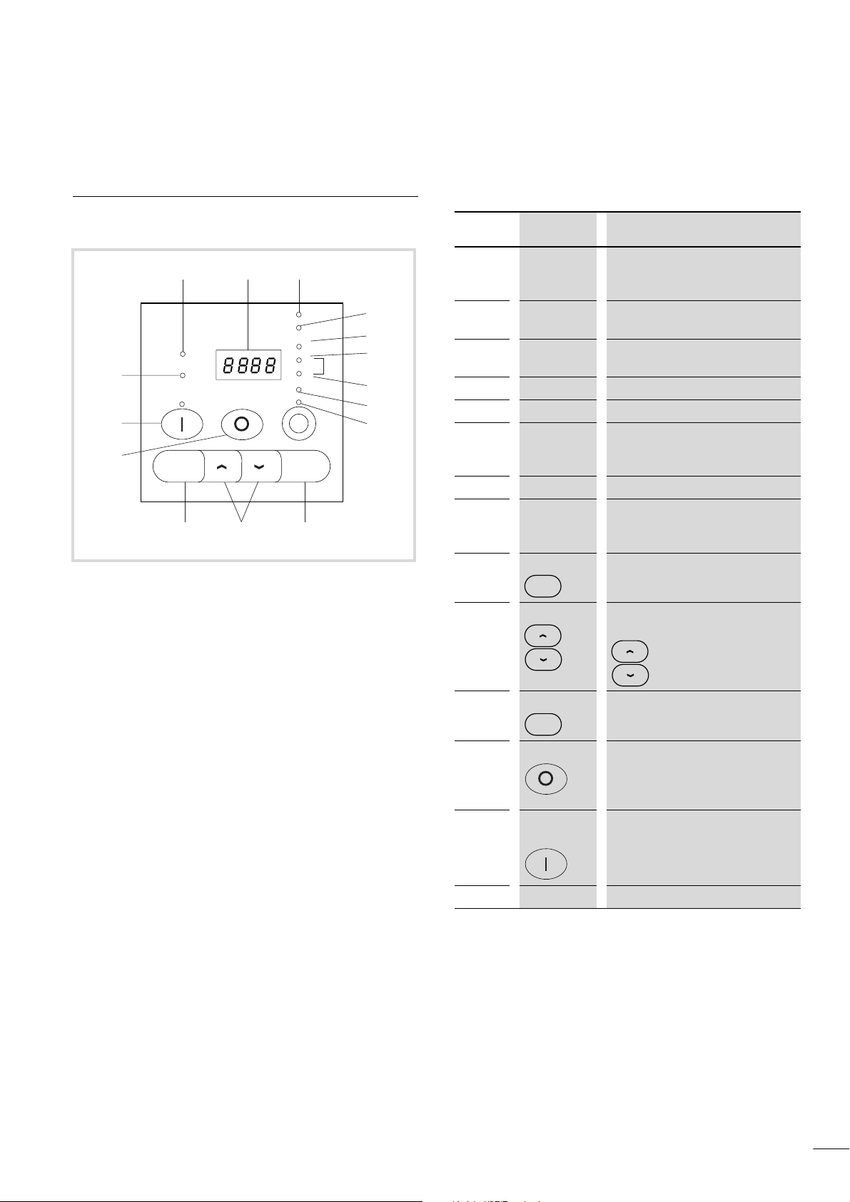
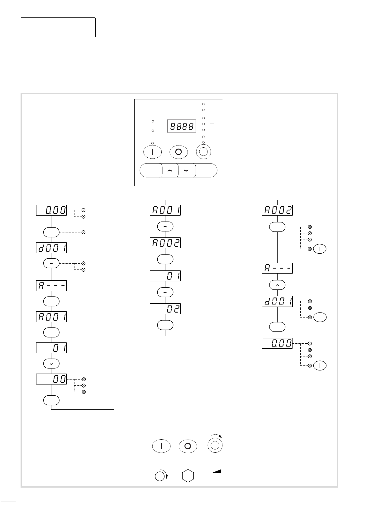
Fault message indication
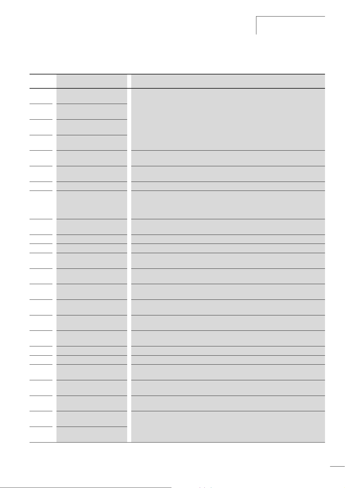
Display Cause Description
E01 Overcurrent in the output stage in
static operation
If the output current reaches an excessive level, the output voltage is switched off. This happens
when
• the frequency inverter’s output is short-circuited,
• the motor is blocked,
• an excessive load is suddenly applied to the output.
E02 Overcurrent in the output stage
during deceleration
E03 Overcurrent in the output stage
during acceleration
E04 Overcurrent in the output stage at
standstill
E05 Overload The internal electronic motor protection has switched off the output voltage because the motor was
overloaded.
E06 Overload If the duty factor of the built-in braking transistor of the DF6 is too great, the braking transistor is
switched off (the generated overvoltage disconnects the output voltage).
E07 Overvoltage The output voltage has been switched off because the motor was operating regeneratively.
E08 EEPROM fault If the program memory does not operate reliably due to radio frequency interference or excessive
temperature, the output voltage is switched off.
If the supply voltage is switched off while the RST input is active, an EEPROM fault occurs when the
supply voltage is reapplied.
E09 Undervoltage If the DC voltage is too low, the output voltage is switched off (fault-free function of electronics no
longer possible; any problems, such as overheating of motor and insufficient torque).
E10 Fault in current transformer The output voltage is disconnected when a fault occurs in the built-in current transformer of the DF6.
E11 Processor malfunction The processor does not operate correctly. The output voltage is switched off.
E12 External fault message The output voltage is switched off due to an external fault message which is present on a digital
input configured as an EXT input.
E13 Restart inhibit activated The mains voltage was switched on or an intermittent interruption in the supply voltage has occurred
while unattended start protection (input USP) was active.
E14 Earth fault Earth faults between the U, V or W terminals and earth are being reliably detected. A protective
circuit prevents destruction of the frequency inverter, but does not protect the operating personnel.
E15 Mains overvoltage If the supply voltage is higher than permitted, the output voltage is switched off 100 seconds after
the voltage supply has been switched on.
E16 Intermittent mains failure An intermittent mains failure of at least 15 ms has occurred. This message appears when the
duration of the mains failure is longer than the time entered under PNU b002 (apage 134)
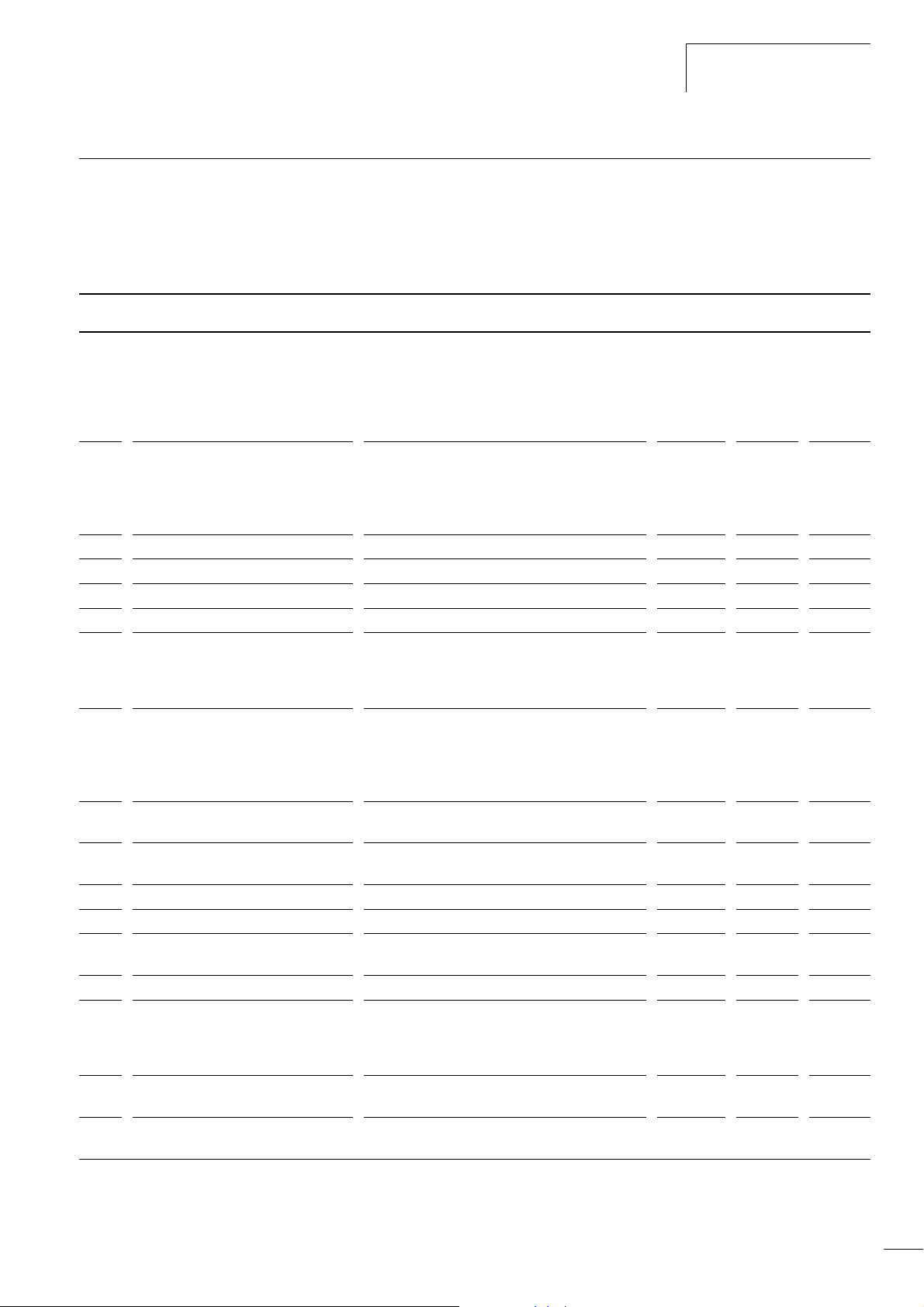
E21 Overtemperature If the temperature sensor installed in the power section records an operating temperature above the
permissible limit value, the output voltage is switched off.
E23 Gate array fault Internal communication error between CPU and gate array
E24 Mains phase failure One of the three mains phases has failed.
E30 IGBT fault If an excessive current is applied at an IGBT (transistor in the power end stage), the output voltage
is switched off to protect the transistor.
E35 Thermistor fault signal If the resistance of the external PTC thermistor connected to the PTC input (terminals TH and CM1)
is too high, the output voltage is switched off.
---- Undervoltage Because the input voltage is too low, the frequency inverter attempts a restart. If the restart fails, a
fault message is triggered to save the undervoltage fault and the frequency inverter switches off.
E60 to
E69
Fault, expansion module 1 A fault has occurred in expansion modules 1 or 2 and their connections. For further information, refer
to the manuals for the affected expansion module.
E70 to
E79
Fault, expansion module 2

Quick Reference Guide
DF6 Frequency Inverter
02/02 AWB8230-1449GB
6
Other messages
This section describes the messages issued by the DF6 frequency
inverter, for example in standby mode when mains power is
switched off.
Display Cause
The frequency inverter is in standby mode
or
a reset signal is active.
The mains voltage has been switched off.
The waiting time before an automatic
restart is counting down (PNU b001 and
b003, aAWB8230-1413GB section
“Automatic restart after a fault“,
page 132).
The default settings have been selected and
the frequency inverter is in the initialization
phase (PNU b084 and b085,
aAWB8230-1413GB section
“Initialization“, page 147). The values for
the European market (EU) are being
initialized. For non-European models,
versions for North America (USA) and Japan
(JP) are available.
Initialization of the fault history register
Copy station – copying in progress.
No data available, e.g. display under
PNU d081 and d086, when the fault history
register is empty the display under
PNU d004, when PID control is not active.

02/02 AWB8230-1449GB Standard form for user defined
parameter settings
7
Standard form for user defined parameter settings
The DF6 frequency inverters have programmable parameters. For
a detailed description of the parameters, see the specified page in
the manual (AWB8230-1413GB). In the free Setpoint columns
below, you can list the changes you have made from the default
settings.
PNU Meaning Value range Def. Setpoint
A001 Frequency setpoint input • 00: Potentiometer
• 01: Analog inputs O, O2 or OI
• 02: PNU F001 or A020
• 03: RS 485 serial interface
• 04: Optional module in slot 1
• 05: Optional module in slot 2
01
A002 Start signal definition • 01: Input FWD/REV
• 02: ON key
• 03: RS 485 serial interface
• 04: Optional module in slot 1
• 05: Optional module in slot 2
01
A003 Base frequency 30 to 400 Hz 50
A203 Base frequency (second parameter set) 30 to 400 Hz 50
A004 Maximum end frequency 30 to 400 Hz 50
A204 End frequency (second parameter set) 30 to 400 Hz 50
A005 AT selection • 00: AT input switches between analog input O
and OI
• 01: AT input switches between analog input O
and O2
00
A006 O2 selection • 00: O2 signal only
• 01: Sum of signals at O2 and O/OI without
direction reversal
• 02: Sum of signals at O2/O or OI with direction
reversal
00
A011 Frequency at minimum setpoint value
(terminal O-L)
0.00 to 400 Hz 0.00
A012 Frequency at maximum setpoint value
(terminal O-L)
0.00 to 400 Hz 0.00
A013 Minimum setpoint value (terminal O-L) 0 to 100 % 0
A014 Maximum setpoint value (terminal O-L) 0 to 100 % 100
A015 Starting frequency (terminal O-L) • 00: Apply PNU A011 to motor
• 01: Apply 0 Hz to motor
01
A016 Analog input filter time constant 1 to 30 8
A019 Fixed frequency selection • 00: Binary selection through digital inputs
FF1 to FF4
• 01: Bitwise selection through digital inputs
SF1 to SF7
00
A020 Frequency setpoint definition PNU A001
must be 02
0.00 to 400 Hz 0.00
A220 Frequency setpoint definition; PNU A001
must be 02 (second parameter set)
0.00 to 400 Hz 0.00

Quick Reference Guide
DF6 Frequency Inverter
02/02 AWB8230-1449GB
8
A021 1st fixed frequency 0.00 to 400 Hz 0.00
A022 2nd fixed frequency 0.00 to 400 Hz 0.00
A023 3rd fixed frequency 0.00 to 400 Hz 0.00
A024 4th fixed frequency 0.00 to 400 Hz 0.00
A025 5th fixed frequency 0.00 to 400 Hz 0.00
A026 6th fixed frequency 0.00 to 400 Hz 0.00
A027 7th fixed frequency 0.00 to 400 Hz 0.00
A028 8th fixed frequency 0.00 to 400 Hz 0.00
A029 9th fixed frequency 0.00 to 400 Hz 0.00
A030 10th fixed frequency 0.00 to 400 Hz 0.00
A031 11th fixed frequency 0.00 to 400 Hz 0.00
A032 12th fixed frequency 0.00 to 400 Hz 0.00
A033 13th fixed frequency 0.00 to 400 Hz 0.00
A034 14th fixed frequency 0.00 to 400 Hz 0.00
A035 15th fixed frequency 0.00 to 400 Hz 0.00
A038 Frequency in jog mode 0 to 9.99 Hz 1.00
A039 Motor stop in jog mode through • 00: Coasting
• 01: Deceleration ramp
• 02: DC braking
• 03: Without prior stop signal, motor coasts to halt
• 04: Without prior stop signal, stopping with
deceleration ramp
• 05: Without prior stop signal, stopping with
DC braking
00
A041 Voltage boost characteristics • 00: Manual
• 01: Automatic
00
A241 Boost characteristic
(second parameter set)
• 00: Manual
• 01: Automatic
00
A042 Percentage voltage increase with
manual boost
0.0 to 20 % 1.0
A242 Percentage voltage increase on
manual boost (second parameter set)
0.0 to 20 % 1.0
A043 Maximum boost at x % of the
base frequency
0.0 to 50 % 5.0
A243 Maximum boost at x % of the base
frequency (second parameter set)
0.0 to 50 % 5.0
A044 U/fcharacteristic • 00: Constant torque curve
• 01: Reduced torque curve
• 02: User-definable
00
A244 U/fcharacteristic (second parameter set) • 00: Constant torque curve
• 01: Reduced torque curve
• 02: User-definable
00
A045 Output voltage 20 to 100 % 100
A051 DC braking • 00: Inactive
• 01: Active
00
A052 DC braking starting frequency 0 to 60 Hz 0.5
A053 DC braking waiting time on deceleration 0 to 5 s 0.0
PNU Meaning Value range Def. Setpoint

02/02 AWB8230-1449GB Standard form for user defined
parameter settings
9
A054 DC braking torque on deceleration 0 to 100 % 0
A055 DC braking duration on deceleration 0 to 60 s 0.0
A056 Behaviour on activation of the DB input • 00: Starts on activation of the input,
ends after PNU A055
• 01: Runs as long as input is active
01
A057 DC braking torque on acceleration 0 to 100 % 0
A058 DC braking duration on acceleration 0 to 60 s 0.0
A059 DC braking frequency • To DV6-340-55K: 0.5 to 15 kHz
• From DF6-340-75K: 0.5 to 10 kHz
3.0
A061 Maximum operating frequency 0.00 to 400 Hz 0.0
A261 Maximum operating frequency
(second parameter set)
0.00 to 400 Hz 0.0
A062 Minimum operating frequency 0.00 to 400 Hz 0.0
A262 Minimum operating frequency
(second parameter set)
0.00 to 400 Hz 0.0
A063 1st frequency jump 0.00 to 400 Hz 0.0
A064 Jump width of the 1st frequency jump 0.00 to 10 Hz 0.5
A065 2nd frequency jump 0.00 to 400 Hz 0.0
A066 Jump width of the 2nd frequency jump 0.00 to 10 Hz 0.5
A067 3rd frequency jump 0.00 to 400 Hz 0.0
A068 Jump width of the 3rd frequency jump 0.00 to 10 Hz 0.5
A069 Acceleration pause waiting frequency 0.00 to 400 Hz 0.0
A070 Acceleration pause waiting duration 0 to 60 s 0.0
A071 PID control • 00: Inactive
• 01: Active
00
A072 P component of the PID control 0.2 to 50 1.0
A073 I component of the PID control 0 to 3600 s 1.0
A074 D component of the PID control 0.0 to 100 s 0.0
A075 Setpoint factor of the PID control 0.01 to 99.99 1.00
A076 Input actual value signal for PID control • 00: Input OI
• 01: Input O
00
A081 AVR function • 00: Active
• 01: Inactive
• 02: Inactive during deceleration
02
A082 Motor voltage for AVR function 380, 400, 415, 440, 460, 480 400
A085 Energy-saving mode • 00: Not active
• 01: Active
00
A086 Response time in energy-saving mode 0 to 100 s 50
A092 2. acceleration time 0.01 to 3600 s 15.0
A292 2nd acceleration time
(second parameter set)
0.01 to 3600 s 15.0
A093 2nd deceleration time 0.01 to 3600 s 15.0
A293 2nd deceleration time
(second parameter set)
0.01 to 3600 s 15.0
PNU Meaning Value range Def. Setpoint

Quick Reference Guide
DF6 Frequency Inverter
02/02 AWB8230-1449GB
10
A094 Changeover from 1st to 2nd time ramp • 00: Input 2CH
• 01: PNU A095 or A096
00
A294 Changeover from 1st to 2nd time ramp
(second parameter set)
• 00: Input 2CH
• 01: PNU A095 or A096
00
A095 Changeover frequency on changeover
from first to second acceleration time
0.00 to 400 Hz 0.00
A295 Changeover frequency on changeover
from first to second acceleration time
(second parameter set)
0.00 to 400 h 0.00
A096 Changeover frequency on changeover
from first to second deceleration time
0.00 to 400 Hz 0.00
A296 Changeover frequency on changeover
from first to second deceleration time
(second parameter set)
0.00 to 400 h 0.00
A097 Acceleration characteristic • 00: Linear
• 01: S curve
• 02: U curve
• 03: Inverted U curve
00
A098 Deceleration characteristic • 00: Linear
• 01: S curve
• 02: U curve
• 03: Inverted U curve
00
A101 Analog input OI starting frequency 0.00 to 400 Hz 0.00
A102 Analog input OI end frequency 0.00 to 400 h 0.00
A103 Analog input OI starting current 0 to 100 % 20
A104 Analog input OI end current 0 to 100 % 100
A105 Analog input OI condition for starting
frequency
00: Start at PNU A101
02: Start at 0 Hz
01
A111 Analog input O2 starting frequency –400 to 400 Hz 0.00
A112 Analog input O2 end frequency –400 to 400 Hz 0.00
A113 Analog input O2 starting voltage –100 to 100 % –100
A114 Analog input O2 end voltage –100 to 100 % 100
A131 Curvature of acceleration characteristic 01 to 10 02
A132 Curvature of deceleration characteristic 01 to 10 02
PNU Meaning Value range Def. Setpoint

02/02 AWB8230-1449GB Standard form for user defined
parameter settings
11
PNU Meaning Value range Def. Setpoint
b001 Restart mode • 00: Fault message
• 01: 0 Hz start
• 02: Synchronization to current motor speed and
acceleration
• 03: Synchronization and deceleration
00
b002 Permissible power failure duration 0.3 to 1.0 s 1.0
b003 Waiting time before restart 0.3 to 1.0 s 1.0
b004 Fault message issued immediately • 00: No fault on intermittent mains failure
• 01: Fault on intermittent mains failure
• 02: No fault on intermittent mains failure at
standstill and deceleration
00
b005 Number of restart attempts • 00: 16 restart attempts
• 01: Unlimited number of restart attempts
00
b006 Mains phase failure detection • 00: Inactive
• 01: Active
00
b007 Synchronization frequency on return of
mains power
0.00 to 400 Hz 0.00
b012 Tripping current for electronic motor
protection device
0.2 to 1.2 xIe[A] Ie(inverter)
b212 Tripping current for electronic motor
protection device (second parameter set)
0.2 to 1.2 xIe[A] Ie(inverter)
b013 Characteristic for electronic motor
protection device
• 00: Enhanced protection
• 01: Normal protection
• 03: User-definable protection
01
b213 Characteristic for electronic motor
protection device (second parameter set)
• 00: Enhanced protection
• 01: Normal protection
• 03: User-definable protection
01
b015 Frequency 1 for user-definable motor
protection characteristic
0.00 to 400 Hz 0
b016 Tripping current 1 for user-definable
motor protection characteristic
0.0 to 1000 A 0.0
b017 Frequency 2 for user-definable motor
protection characteristic
0.00 to 400 Hz 0
b018 Tripping current 2 for user-definable
motor protection characteristic
0.0 to 1000 A 0.0
b019 Frequency 3 for user-definable motor
protection characteristic
0.00 to 400 Hz 0
b020 Tripping current 3 for user-definable
motor protection characteristic
0.0 to 1000 A 0.0
b021 Motor current limitation 1 • 00: Inactive
• 01: Active in every operating status
• 02: Inactive during acceleration, otherwise active
01
b022 Tripping current 1 for motor current
limitation
0.5 to 1.5 xIe[A] Iex1.2
b023 Time constant 1 of motor current
limitation
0.1 to 30 s 1.00
b024 Motor current limitation 2 • 00: Inactive
• 01: Active in every operating status
• 02: Inactive during acceleration, otherwise active
1
b025 Tripping current 2 for motor current
limitation
0.5 to 1.5 xIe[A] Iex1.2

Quick Reference Guide
DF6 Frequency Inverter
02/02 AWB8230-1449GB
12
b026 Time constant 2 of motor current
limitation
0.6 to 30 s 1.0
b031 Software dependent parameter
protection
• 00: Through SFT input; all functions inhibited
• 01: Through SFT input; function F001 possible
• 02: Without SFT input; all functions inhibited
• 03: Without SFT input; function F001 possible
• 10: Extended parameters adjustable in RUN mode
01
b034 Running time or Mains On time signal 0 to 65530 h 0
b035 Inhibit direction 00: Motor can run in both directions
01: Motor can only run clockwise
02: Motor can only run anticlockwise
00
b036 Voltage ramp to starting frequency • 00: Start without voltage reduction.
• 01: Minimum voltage reduction, approx. 6 ms
• ...
• 06: Maximum voltage reduction, approx. 36 ms
06
b037 Display mode • 00: All parameters
• 01: Relevant parameters
• 02: Parameters saved under PNU U001 to U012
00
b080 Gain factor, analog output AM 0 to 255 180
b081 Gain factor, analog output FM 0 to 255 60
b082 Increased starting frequency
(e.g. with high level of friction)
0.1 to 9.99 Hz 0.50
b083 Pulse frequency 0.5 to 12 kHz 3.0
b084 Initialization causes • 00: Clearing the fault history register
• 01: Selection of default settings
• 02: Deleting the fault history register and
restoring the default settings
00
b085 Country version • 00: Japan
• 01: Europe
• 02: USA
01
b086 Frequency factor for display through
PNU d007
0.1 to 99.9 1.0
b087 OFF key • 00: Always active
• 01: Not active with control through the
FWD/REV terminals
00
b088 Motor restart after removal of the
FRS signal
• 00: At 0 Hz
• 01: At current motor speed
00
b090 Permissible relative percentage duty
factor for built-in braking transistor
0 to 100 % 0.00
b091 Type of motor stop when Off button is
pressed
• 00: Braking/deceleration ramp
• 01: Free run stop (coasting)
00
b092 Configuration of fan operation • 00: Fan always switched on
• 01: Fan switched on only when motor running
00
b095 Enable built-in braking transistor • 00: Not enabled
• 01: Enabled in RUN mode
• 02: Always enabled
00
b096 Voltage threshold for braking transistor 660 to 760 V 720
b098 Selection of PTC or NTC • 00: No temperature monitoring
• 01: PTC
• 02: NTC
00
b099 Resistance threshold for thermistor input 0 to 9999 O3000
PNU Meaning Value range Def. Setpoint

02/02 AWB8230-1449GB Standard form for user defined
parameter settings
13
b100 User-definable U/f characteristics,
frequency coordinates 1
0.00 to 400 Hz 0
b101 User-definable U/f characteristics,
voltage coordinates 1
0 to U1/PNU A082 0.0
b102 User-definable U/f characteristics,
frequency coordinates 2
0.00 to 400 Hz 0
b103 User-definable U/f characteristics,
voltage coordinates 2
0 to U1/PNU A082 0.0
b104 User-definable U/f characteristics,
frequency coordinates 3
0.00 to 400 Hz 0
b105 User-definable U/f characteristics,
voltage coordinates 3
0 to U1/PNU A082 0.0
b106 User-definable U/f characteristics,
frequency coordinates 4
0.00 to 400 Hz 0
b107 User-definable U/f characteristics,
voltage coordinates 4
0 to U1/PNU A082 0.0
b108 User-definable U/f characteristics,
frequency coordinates 5
0.00 to 400 Hz 0
b109 User-definable U/f characteristics,
voltage coordinates 5
0 to U1/PNU A082 0.0
b110 User-definable U/f characteristics,
frequency coordinates 6
0.00 to 400 Hz 0
b111 User-definable U/f characteristics,
voltage coordinates 6
0 to U1/PNU A082 0.0
b112 User-definable U/f characteristics,
frequency coordinates 7
0.00 to 400 Hz 0
b113 User-definable U/f characteristics,
voltage coordinates
0 to U1/PNU A082 0.0
PNU Meaning Value range Def. Setpoint

Quick Reference Guide
DF6 Frequency Inverter
02/02 AWB8230-1449GB
14
PNU Meaning Value range Def. Setpoint
C001 Function of digital input 1 Function of digital input 1
• 01: REV, anticlockwise operation
• 02: FF1, first fixed frequency input
• 03: FF2, second fixed frequency input
• 04: FF3, third fixed frequency input
• 05: FF4, fourth fixed frequency input
• 06: JOG, jog mode
• 07: DB, DC braking
• 08: SET, second parameter set
• 09: 2CH, second time ramp
• 11: FRS, controller inhibit
• 12: EXT, external fault
• 13: USP, unattended start protection
• 14: CS, heavy mains starting
• 15: SFT, parameter protection
• 16: AT, analog input selection
• 18: RST, reset
• 20: STA, three-wire control start signal
• 21: STP, three-wire control stop signal
• 22: STA, three-wire control direction
• 23: PID, activate PID control
• 24: PIDC, reset integral component of PID control
• 27: UP, remote access, acceleration
• 28: DWN, remote access, deceleration
• 29: UDC, reset frequency with remote control
• 31: OPE, setpoint value through keypad
• 32 to 38: Bitwise fixed frequencies
• 39: OLR, change over current limit
• NO: no, no function
18
C002 Function of digital input 2 Values aPNU C001 16
C003 Function of digital input 3 Values aPNU C001 03
C004 Function of digital input 4 Values aPNU C001 02
C005 Function of digital input 5 Values aPNU C001 01
C011 Digital input 1 • 00: Make contact
• 01: Break contact
00
C012 Digital input 2 Values aPNU C011 00
C013 Digital input 3 Values aPNU C011 00
C014 Digital input 4 Values aPNU C011 00
C015 Digital input 5 Values aPNU C011 00
C019 Digital input FW Values aPNU C011 00
C021 Signal at relay output K23-K24 • 00: RUN signal
• 01: FA1, frequency reached
• 02: FA2, frequency exceeded
• 03: OL, Overload
• 04: OD, PID deviation exceeded
• 05: AL, fault
• 06: FA3, frequency reached (1)
• 08: IP, mains failure, immediate stop
• 09: UV, undervoltage
• 11: ONT, mains On time exceeded
• 12: RNT, running time exceeded
• 13: THM, motor thermal overload
01
C022 Signal at relay output K33-K34 Values aPNU C021 00
C026 Signal at relay terminals K11-K12 Values aPNU C021 05

02/02 AWB8230-1449GB Standard form for user defined
parameter settings
15
C027 Output, FM output • 00: Output frequency, PWM signal
• 01: Output current
• 03: Output frequency, FM signal
• 04: Output voltage
• 05: Inverter input power
• 06: Thermal load ratio
• 07: Ramp frequency
00
C028 Output, AM output • 00: Output frequency, PWM signal
• 01: Output current
• 04: Output voltage
• 05: Inverter input power
• 06: Thermal load ratio
• 07: Ramp frequency
00
C029 Output, AMI output Values aPNU C028 00
C031 Relay output K23-K24 • 00: Make contact
• 01: Break contact
00
C032 Relay output K33-K34 Values aPNU C031 00
C036 Relay terminals K11-K12, signalling relay Values aPNU C031 01
C040 Overload alarm signal • 00: Always
• 01: Only at constant speed
01
C041 Overload alarm threshold at relay output
K11 to K34
0 to 2 xIe[A] Ie
C042 Frequency from which FA2 is switched on
during acceleration
0.00 to 400 Hz 0.00
C043 Frequency from which FA2 is switched off
during deceleration
0.00 to 400 Hz 0.00
C044 PID control deviation
(from the maximum set point value)
0 to 100 % 3.0
C070 Serial interface, programming through: • 02: Keypad
• 03: RS 485 serial interface
• 04: Optional module in slot 1
• 54: Optional module in slot 2
02
C071 Baud rate • 03: 2400 bit/s
• 04: 4800 bit/s
• 05: 9600 bit/s
• 06: 19200 bit/s
04
C072 Address 01 to 32 1
C073 Data word length: 7 or 8-bit 7
C074 Parity • 00: None
• 01: Even
• 02: Odd
00
C075 Stop bits: 1 or 2 1
C078 Transmission waiting time 0 to 1000 ms 0
C081 Compensation of setpoint signal at
terminal O
0 to 65530 Depending
on inverter
model
C082 Compensation of setpoint signal at
terminal OI
0 to 65530
C083 Compensation of setpoint signal at
terminal O2
0 to 65530
C085 Thermistor matching 0 to 1000 105
C086 Offset, AM terminal 0 to 10 V 0.0
PNU Meaning Value range Def. Setpoint

Quick Reference Guide
DF6 Frequency Inverter
02/02 AWB8230-1449GB
16
C087 Gain, AMI terminal 0 to 255 80
C088 Offset, AMI terminal 0 to 20 mA 0.0
C091 Debug mode • 00: Debug mode On
• 01: Debug mode Off
00
C101 Use saved UP/DWN setting • 00: Use PNU A020
• 01: Use saved UP/DWN frequency
00
C102 Reset signal • 00: On rising edge
• 01: On falling edge
• 02: On rising edge, only on fault
00
C103 Behaviour on reset • 00: 0 Hz start
• 01: Synchronization to the motor speed
00
C121 Zero-point matching, terminal O 0 to 65530 (6553) Depending
on inverter
model
C122 Zero-point matching, terminal OI 0 to 65530 (6553)
C123 Zero-point matching, terminal O2 0 to 65530 (6553)
PNU Meaning Value range Def. Setpoint
PNU Meaning
d001 Output frequency display
d002 Output current display
d003 Direction of rotation display
d004 PID feedback display
d005 Status of digital inputs 1 to 8
d006 Status of digital outputs 11 to 15
d007 Scaled output frequency
d013 Output voltage
d014 Electrical input power
d016 Running time
d017 Mains On time
d080 Total number of malfunctions
d081 First (most recent) fault
d082 Second fault
d083 Third fault
d084 Fourth fault
d085 Fifth fault
d086 Sixth fault
d090 Warning

02/02 AWB8230-1449GB Standard form for user defined
parameter settings
17
PNU Meaning Value range Def. Setpoint
F001 Frequency setpoint value 0.00 to 400 Hz 0.0
F002 Acceleration time 1 0.01 to 3600 s 30.0
F202 Acceleration time 1 (second parameter set) 0.01 to 3600 s 30.0
F003 Deceleration time 1 0.01 to 3600 s 30.0
F203 Deceleration time 1 (second parameter set) 0.01 to 3600 s 30.0
F004 Direction of rotation • 00: Clockwise operation
• 01: Anticlockwise operation
00
PNU Meaning Value range Def. Setpoint
H003 Motor rating 0.2 to 160 kW Depending
on inverter
model
H203 Motor rating (second parameter set) 0.2 to 160 kW
H004 Number of motor poles 2, 4, 6, 8 4
H204 Number of motor poles
(second parameter set)
2, 4, 6, 8 4
H006 Motor stabilization constant 0 to 255 100
H206 Motor stabilization constant
(second parameter set)
0 to 255 100
PNU Meaning Value range Def. Setpoint
U001 User-defined parameters PNU A001 to H206 no
U002 no
U003 no
U004 no
U005 no
U006 no
U007 no
U008 no
U009 no
U010 no
U011 no
U012 no
Other manuals for DF6-340 Series
1
Table of contents
Other Moeller Inverter manuals
Popular Inverter manuals by other brands

Lenze
Lenze L-force 8400 Series Mounting instructions

Sumitomo
Sumitomo CAI40C Operation manual

LONCIN
LONCIN LC 2000i Service manual

LC-POWER
LC-POWER LCCD-A1 user manual

Büttner Elektronik
Büttner Elektronik Power Line MT PL 300 SI Installation & user manual

Power Electronics
Power Electronics SD700 Series Hardware and installation manual

Sincro
Sincro EW 170 MDC Use and maintenance manual

TECO
TECO L510S Series Quick manual

Targus
Targus 100W Automobile Power Inverter quick start guide

Goodwe
Goodwe MS Series user manual

Iris Technology Corporation
Iris Technology Corporation QP-1800 owner's manual

Bodine
Bodine ELI-S-400-2HR Installation and operation instruction