SATAM 7889 Series Owner's manual

SATAM Siège Social : Paris Nord II – 5, rue des Chardonnerets
Usine de Falaise – Avenue de Verdun – B.P. 129 – 14700 FALAISE – France B.P. 85012 – Tremblay- en-France – 95931 Roissy C.D.G. Cedex - France
Tél. : +33 (0)2 31 41 41 41 Tél. : +33 (0)1 49 90 77 00
Fax : +33 (0)2 31 40 75 61 Fax : +33 (0)1 49 90 77 99
SIRET 495 233 124 000 17 SA au capital de 6 037 000 € – RCS Bobigny B 495 233 124
CODE APE 2813 Z SIRET 495 233 124 000 17 – Code APE 2813 Z – N° TVA : FR 48 495 233 124
SERIES 7889 METER PRESET
MANUAL
DESCRIPTION - INSTALLATION - OPERATION -
SERVICING
U508217-e – Revision 02 – 24 February 2009
This document consists of 12 pages, including the flyleaf
This document is the property of SATAM
And may not transmitted to third parties without prior authorisation
SATAM may modify this document without prior authorisation
In conformity with the European directive 94/9/CE-ATEX

Edition du 24/02/09 / 12 U508217-e Revision : 22
Summary
SECTION 1. INTRODUCTION.........................................................................................................3
A. GENERAL ................................................................................................................................3
SECTION 2. DESCRIPTION............................................................................................................4
A. GENERAL ................................................................................................................................4
B. SPECIFICATIONS. ..................................................................................................................4
SECTION 3. INSTALLATION..........................................................................................................5
A. MOUNTING..............................................................................................................................5
B. TRIMMING RIGHT-HAND WHEEL TO ZERO.........................................................................5
C. FIRST STAGE KNOCKOFF CHANGE....................................................................................6
D. OPERATIONAL CHECK..........................................................................................................7
SECTION 4. OPERATION...............................................................................................................8
SECTION 5. SERVICE.....................................................................................................................9
A. GENERAL. ...............................................................................................................................9
B. CLEANING...............................................................................................................................9
C. RECOMMENDED LUBRICANTS. ...........................................................................................9
D. LUBRICATION.........................................................................................................................9
F. TROUBLESHOOTING. ..........................................................................................................10

Edition du 24/02/09 / 12 U508217-e Revision : 23
SECTION 1. INTRODUCTION
A. GENERAL
These instructions are for servicing the Series 7889 Preset Registers.
Every Meter Register is thoroughly tested at the meter factory when installed on the meter. However, like any
precision mechanism, it requires periodic care to ensure maximum service. This manual is for use in areas where
factory rebuilding facilities and adequate exchange stocks are not readily accessible.
Where manufacturer's replacement stocks are available, it is important that no attempt be made to repair any meter
register defective within the terms of the warranty as by doing so, the warranty is void and the user is deprived of
the protection provided by the warranty. It is recommended that, when possible, meter registers be replaced and
the defective unit returned to the meter manufacturer.

Edition du 24/02/09 / 12 U508217-e Revision : 24
SECTION 2. DESCRIPTION
A. GENERAL
1. The Series 7889 Meter Preset is used in fluid flow
applications where it is desired to close a valve after a
predetermined amount of liquid has passed through.
2. In technical terms, the Preset is a non-repeating,
predetermining counter that is driven by and normally
mounted on a flow meter. It has a two-stage output
that is normally used to close a valve in two stages.
3. The Preset is used in combination with other
Veeder-Root meter accessories.
B. SPECIFICATIONS.
1. Input. The Preset is driven by a rotating shaft from a
customer-supplied flow meter. The type of input
coupling should be specified when ordering. Maximum
torque to drive the Preset through a knockoff is 40
ounces per inch. Average running torque is below 4
ounces per inch.
2. Mounting. See Figure 1. There are eight tapped
mounting holes for use with ¼-28 screws. The Preset
is designed to mount directly on a.
3. Valve and Switch Connections. The Preset can be
connected to a two-stage valve by customer supplied,
direct linkage or by an electrical switch with linkage.
Either linkage connects to a rotating knockoff plate on
the bottom of the Preset case with a 114-28 screw
(Figure 1). The rated first-stage valve load is 60
pounds.
4. Outline Dimensions. See Figure 1.
5. Flow Rate. The maximum speed of the right-hand
wheel (least significant digit) is 250 rpm. With a 1:1
ratio between the input and the right-hand wheel, the
maxi- mum input speed would also be 250 rpm. If one
revolution of the right-hand wheel represents 10
gallons, the maxi- mum flow rate would be 2500
gallons per minute. Gear plates are available to
provide various ratios of input revolutions of the right-
hand wheel.
6. Preset Number. 4 or 5 digits. Preset in additive
direction by individually actuating five preset buttons
(maximum preset capacity 99999)
7. Display. 4 or 5 wheels with ½ inch white digits on
black background.
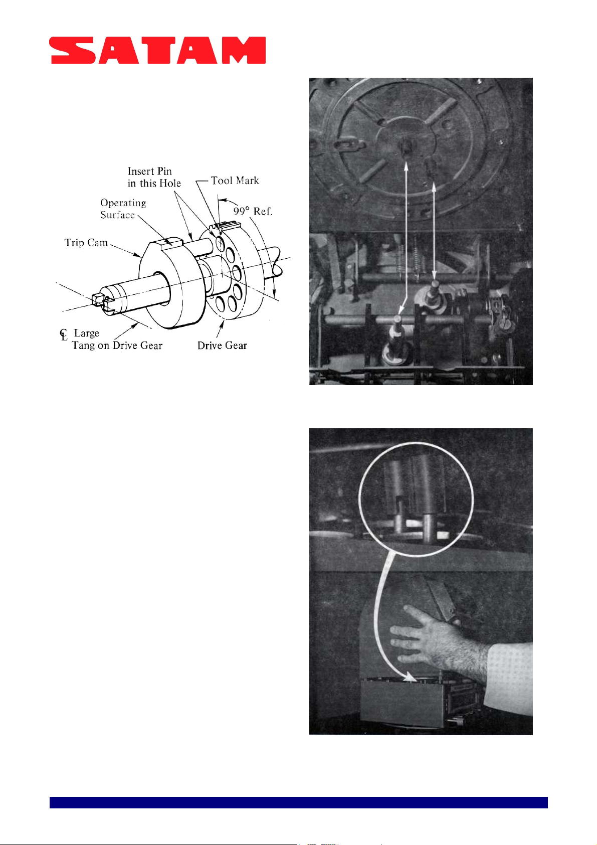
8. Output (Knockoff). Two-stage knockoff. Unit
counts down from preset number. First stage knockoff
point is set at the factory to customer's specification at
90, 80, 70, 60, 50, 40, 30, 20, 10, 9, 8, 7, 6, 5,4, or 3.
An option al three-finger rake provides first stage
knockoff at a number between 900 through 100 in
increments of 100. The setting can be internally
changed by the customer in the field. Second (final
stage) knockoff occurs when aIl wheels reach zero.
See Figure 1 for angular travel of knockoff plate.
9. Interlock. The Preset has a unique interlock feature.
The Preset buttons cannot be actuated until the SET
button is depressed (latched). The SET button cannot
be latched with the valve load applied. Therefore, the
preset number cannot be changed while fluid is
flowing.
WARNING: IF THE PRESET OPERATING HANDLE IS
MOUNTED IN THE 5 O'CLOCK POSITION, THE HANDLE
COULD STRlKE THE OPERATOR'S HAND WHEN
DEPRESSING THE EMERGENCY STOP BUTTON.
10. Emergency Stop. The STOP button will "dump"
both first and final stages of the valve to provide
complete shutdown.
11. Options. Presets are available with a Series 7856
explosion-proof switch for use with electrically
operated valves. The Preset can be integrally mounted
to a Veeder-Root Meter Register or to a Meter Register
with Ticket Printer.
Figure 1. Dimensions

Edition du 24/02/09 / 12 U508217-e Revision : 25
SECTION 3. INSTALLATION
WARNING: WHEN THE PRODUCT IS USED TO
CONTROL A MACHINE OR PROCESS WHERE
PERSONAL INJURY OR EQUIPMENT DAMAGE
MIGHT OCCUR AS A RESULT OF FAILURE OF ANY
ELECTRICAL OR OTHER PRODUCT FUNCTION,
YOU ARE URGENTLY RECOMMENDED TO INSIST
ON INSTALLATION OF SAFEGUARDS WHICH
WOULD PROTECT THE OPERATION AND/OR
MACHINE IN THE EVENT OF ANYUNEXPECTED
OPERATION OF THE MACHINE OR PROCESS.
A. MOUNTING.
CAUTION: BEFORE INSTALLING THE METER PRESET,
REMOVE AND DISCARD THE TWO HEX HEAD SCREWS
AND WASHERS THAT SECURE THE KNOCK OFF PLATE
TO THE BOTTOM OF THE PRESET. THEN, HOLD THE
SPRINGLOADED KNOCKOFF PLATE AGAINST THE
PRESET UNTIL INSTALLED ON A FLOW METER OR
ADAPTER. FAILURE TO COMPLY MAY RESULT IN
DAMAGE TO THEKNOCKOFF PLATE RETURN SPRING.
1. Remove and discard the two hex head screws and
washers that secure the spring loaded knockoff
plate to the bottom of the Preset (Figure 2). Ensure
that the knockoff plate does not rail away from the
Preset or damage to the knockoff plate return
spring may result.
Figure 2. Removal of Preset Retaining Screws.
2. Install the Preset on a flow meter or adapter, taking
care to properly engage mating couplings. Secure with
1/4-28 screws and lock washers. CAUTION: Screws
must not enter tapped holes more than 0.312 in.
WARNING: IN INSTALLATION AND USE OF THIS
PRODUCT WITH AN ELECTRICAL SWITCH, COMPLY
WITH THE NATIONAL ELECTRICAL CODE; FEDERAL,
STATE AND LOCAL CODES; AND TURN OFF POWER
AND TAKE OTHER NECESSARY PRECAUTIONS DURING
INSTALLATION, SERVICE AND REPAIR TO PREVENT
PERSONAL INJURY, PROPERTY LOSS AND EQUIPMENT
DAMAGE.
3. Install the linkage between the knockoff plate and
valve or switch. If the Preset is equipped with a Series
7856 explosion-proof switch, connect wires per
installation instructions packed with the switch.
4. Ensure that there is still some knockoff plate over
travel after the valve is fully open.
5. Verify that after the valve closes, the knockoff plate
has rotated the correct distance of 15°, 45' plus 7 °
(Figure 1) and that there is some over travel still left in
the plate.
B. TRIMMING RIGHT-HAND WHEEL TO ZERO.
If the right-hand wheel does not read zero after product
flow stops, adjust as follows:
Note: SET button must be released (unlatched) during
trimming procedure
1. Remove the lockwired plate covering the trim holes
on the right Side of the Preset. Older models have
trim hole plugs. Insert one small screwdriver blade
in each of the two trim holes (Figure 3).
Figure 3. Trimming the Right-Hand Wheel.
2. Fit the tips of the screwdrivers into the slots in the
side of the plastic parts. By prying with the front
screwdriver and holding the gear train stationary with
the rear screwdriver, adjust the knockoff cam as
follows:
CAUTION: ADJUST THE KNOCKOFF CAM ONLY lN THE
DIRECTION INDICATED lN THE FOLLOWING STEPS.
ADJUSTMENT OF THE CAM lN THE WRONG DIRECTION
COULD DAMAGE THE INTERNAL STOP AND CAUSE A
RUNA WAY DELlVERY. IF STRONG RESISTANCE IS
ENCOUNTERED lN ONE DIRECTION DURING
ADJUSTMENT, THE INTERNAL STOP HAS BEEN
REACHED. DO NOT ATTEMPT FURTHER ADJUSTMENT
lN THAT DIRECTION.

Edition du 24/02/09 / 12 U508217-e Revision : 26
a. If the final knockoff point is greater than zero, adjust
the cam backward (clockwise when looking into the
trim hole) only. Do not attempt to adjust the cam
forward since you cannot reach zero without breaking
the internal stop. The cam must be adjusted 10 clicks
for a 1 digit change in the right-hand wheel. For
example, if a Preset final knockoff point was 0003, the
cam would be moved 30 clicks.
b. If the final knockoff point is less than zero, adjust the
cam forward (counterclockwise when looking into the
trim hole) only. Do not attempt to adjust the cam
backward since you cannot reach zero without
breaking the internal stop. The cam must be adjusted
10 clicks for a 1 digit change in the right-hand wheel.
For example, if a Preset final knockoff point was 9998,
the cam would be adjusted 20 clicks.
3. After adjustment, set a small number into the Preset
and deliver product. The final knockoff point should be
zero. If not, repeat the adjustments until zero is
reached.
4. Install the trim hole plugs or plate. Secure the plate
with screws and a new lockwire.
C. FIRST STAGE KNOCKOFF CHANGE.
Proper operation of the Preset depends on the correct
relationship between the first and second stage rakes
and the notches in the wheels. If this factory setting is
disturbed, the unit will not operate properly. To change
the first stage knockoff setting, perform the following
procedure:
1. Cut the lockwire that is threaded through the four
bolts securing the Register to the Preset.
2. Remove the four mounting bolts.
3. With the assembly in an upright position, lift the
Meter Register from the Meter Preset.
CAUTION: DO NOT BEND OR TWIST RAKES WHEN
SETTING FIRST STAGE KNOCKOFF. IF RAKES ARE
DAMAGED, SEE SECTION 5 FOR TEMPORARY
EMERGENCY ADJUSTMENT.
4. Lift both rakes away from the wheels in the Preset
(Figure 4).
Figure 4. Lifting Rakes.
5. Set the first stage knockoff at a number from 3
through 900 by first depressing the SET button, then
one, two or three character wheel Preset buttons. The
Preset must be equipped with an option al three-finger
rake to obtain a first stage knockoff at a number
between 100 and 900.
6. Release the SET button by rotating the knockoff
plate.
7. Ensure that the character wheel disc inserts
(Figure 5) are located as follows:
a. For first stage knockoff at a number from 3 through
9, ensure that aIl disc inserts are installed in the
second character wheel (second wheel from right). .
b. For first stage knockoff at a number from 10 through
90, remove the disc insert nearest the top of the
second character wheel and install it in any other open
position in the wheel. Save the disc insert for future
changes in knockoff settings if there are no open
positions.
c. For first stage knockoff at a number from 100
through 900, remove the disc insert nearest the top of
the second and third character wheels. Install them in
any other open positions in these two wheels. Save the
disc inserts for future changes in knockoff settings if
there are no open positions.
Figure 5. Removal of Disc lnsert from Wheel.

Edition du 24/02/09 / 12 U508217-e Revision : 27
8. Push the trip cam to the left to disengage it from the
drive gear (Figure 6).
9. Rotate the trip cam until its operating surface is
straight up (Figure 6). ln this position, the operating
surface pulls the rake when the desired number on the
first character wheel is displayed in the window.
Figure 6. Trip Cam Positioning for First Stage Knockoff.
10. Engage the trip cam with the drive gear (Figure 6).
Note:
If the first stage knockoff number is set very low,
both the first and final knockoffs could appear to occur
simultaneously during a high flow rate.
11. Lower the rakes toward the front of the Preset to
their operating position.
CAUTION: DO NOT BEND OR TWIST RAKES. BE SURE
RAKES ARE PROPERLY POSITIONED OVER ECCENTRIC
WHEN METER REGISTER IS LOWERED ONTO THE
PRESET. BE SURE PROTRUDING SHAFTS DO NOT
CONTACT THE RAKES. IF RAKES ARE DISTURBED, SEE
"TEMPORARY/EMERGENCY ADJUSTMENT" lN SECTION
5.
12. Install the Meter Register on top of the Meter
Preset with attention to proper alignment of the two
"up-down" shafts (Figures 7 and 8). Secure the units
together with the four bolts and a new lockwire.
D. OPERATIONAL CHECK.
Before putting the Preset into use, perform a complete
check of the unit and associated delivery equipment
per Section 4.
Figure 7. Shaft Alignment Before Installation of Meter
Register on Meter Preset
.
Figure 8. Installation of Meter Register on Meter Preset.

Edition du 24/02/09 / 12 U508217-e Revision : 28
SECTION 4. OPERATION
1. Depress the SET button into its latched position.
The inward movement of the SET button causes:
a. The input drive to de-clutch so that its internal
parts are disconnected from the flow meter.
b. A "gate" to open that had blocked the Preset
buttons from operating.
2. Depress the appropriate Preset buttons to display
the quantity of fluid to be delivered. One depression
of each button will rotate its corresponding wheel
1/10 revolution or one digit in an additive direction.
Presetting one wheel will not affect other wheels.
3. Open the valve to start fluid flow by moving the
linkage between the Preset and the valve. (A handle
is normally supplied by the valve or meter
manufacturer for this function. Units with Series
7856 Switch are equipped with a handle.) This
action rotates the knockoff plate on the bottom of the
Preset case and:
a. The SET button pops out which locks out the
Preset buttons and engages the clutch between the
input shaft and the wheels.
b. The knockoff plate on the bottom of the Preset
case has two tabs that project into the case. When
the valve load is applied and the knockoff plate
rotates, the tabs move internal latches into their
"loaded" positions.
c. The knockoff movement locks out the SET button.
d. Fluid starts to flow. The flow meter drives the
Preset wheels directly in a subtractive direction.
e. When the first stage knockoff number is reached,
a series of notches in the wheels becomes aligned
and the first stage rake drops into the notches.
Then, a cam pulls the rake forward to release one of
the previously loaded latches. The release of the
latch allows the knockoff plate to move back
approximately 15°, 45' for a partially closed valve.
f. When the wheels reach zero, a second rake drops
into the notches and another cam pulls this rake
forward. This action releases the final latch and
allows the plate to move another 7°for a fully clo sed
valve.

Edition du 24/02/09 / 12 U508217-e Revision : 29
SECTION 5. SERVICE
A. GENERAL.
The Meter Preset is adjusted and lubricated at the
factory, but periodic cleaning and lubrication is
required for maximum service. Service intervals
must necessarily be left to individual users due to
varying conditions of operation.
B. CLEANING.
Remove dirt from character wheels and ail drive
gears with a small brush.
C. RECOMMENDED LUBRICANTS.
OIL:
Temperature Range -65°F to +275°F
Chemlube 201 Oil
Exxon Instrument Oil
Aero shell Fluid No. 12 or Equivalent
GREASE:
Temperature Range -65°F to +300°F
D. LUBRICATION.
1. Apply oil to aIl rotating parts.
2. Apply grease to aIl other moving metal parts.
E. TEMPORARY/EMERGENCY RAKE
ADJUSTMENT.
1. If the Preset fails to knock off due to damaged
rakes caused by banging, bending or twisting,
temporary adjustments can be made while waiting
for a replacement unit.
2. Using extreme caution, bend the rake fingers to
obtain proper rake positioning (Figure 9).
Figure 9. Rake Positioning

Edition du 24/02/09 / 12 U508217-e Revision : 210
F. TROUBLESHOOTING.
Refer to Figures 10, 11, and 13 for parts identification when using Troub1eshooting Table 1.
Table 1. Series 7889 Meter Preset Troubleshooting.
TROUBLE POSSIBLE CAUSE CORRECTION
Any wheel cannot be preset
Broken preset pawl (Figure 11).
Displaced extension spring between base
of Preset and Preset pawl (Figure 11 ).
Install new preset pawl (Paragraph G).
Replace extension spring.
Any wheel split
(Number not centered in window).
Broken rack (Figure 11). pin ion or mating
eccentric (Figure 13).
Pinion out of time. Stud on wheel shaft
pinion is not straight up (Figure 13).
Groove pin not flush with bottom of rack
(Figure 11).
Install new rack (Paragraph H), or pinion or
mating eccentric.
Remove wheel shaft group (Paragraph G).
Rotate pin ion until stud on pinion is
straight up.
Drive groove pin flush with bottom of rack.
First knockoff fails.
Bent rake.
Align rake for proper clearance and
engagement with wheels (Figure 9).
Final knockoff fails.
Misalignment of rake with wheels.
Knockoff plate binds.
Broken extension spring between strap
securing left si de of wheel shaft and
knockoff plate (Figure 10).
Broken meter coupling.
Align rake for proper clearance and
engagement with wheels (Figure 9).
Clean and lubricate knockoff plate
(Paragraphs B, C and D).
Install new extension spring.
Install new meter coupling.
Preset shuts off at first knockoff.
Improperly adjusted rakes.
Broken first stage knockoff pawl (Figure
10).
Adjust rakes (Figure 8).
Install new first stage knockoff pawl.
Knockoff plate binds.
Missing knockoff plate insert.
Dirty knockoff plate.
Install new insert where necessary.
Clean) and lubricate knockoff plate
(Paragraphs B, C and D).
Can't trim right-hand wheel to
consistent zero after knockoff.
Variations in fluid flow rate caused by
fluctuating fluid pressure
Stabilize fluid pressure.
Set button fails to return to "OFF"
position.
Broken rack (Figure 11). pinion or mating
eccentric (Figure 13).
Pinion out of time. Stud on wheel shaft pin
ion is not straight up (Figure 13).
Install new rack (Paragraph H), or pinion or
mating eccentric.
Remove wheel shaft group (Paragraph G).
Rotate pinion until stud on wheel shaft
pinion is straight up.

Edition du 24/02/09 / 12 U508217-e Revision : 211
Figure 10. Meter Preset Parts Identification (Wheels Installed).
Figure 11. Meter Preset Parts Identification (Wheels Removed).

Edition du 24/02/09 / 12 U508217-e Revision : 212
Figure 12. Aligning Transfer Pillions on Pinion Shaft.
Figure 13. Character Wheel Shaft Group Parts Identification.
Table of contents
Other SATAM Measuring Instrument manuals
Popular Measuring Instrument manuals by other brands

Teledyne Lecroy
Teledyne Lecroy PCI Express Gen 4x8 OCuLink user manual

SCHNIER
SCHNIER HMG 11/03 operating manual

Proteus
Proteus Proteus user manual

Tektronix
Tektronix RSA3408B Technical reference

multicomp pro
multicomp pro MP780966 user manual

Katronic Technologies
Katronic Technologies KATflow 210 operating instructions