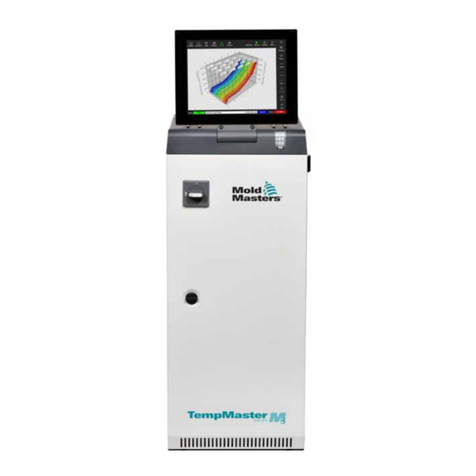
Mold-Masters TempMaster XL-2 Series User manual

XL-2-Series
user manual
revision 1.1
www.moldmasters.com

Amendment Record XL-2 Manual
Page 2 Mold-Masters®Revision 1.1
Amendment Record XL-2 Series Manual
Issue Date Amendments Author Authorised
1.0 July 04 First Issue DT JN
1.1 Nov 05 Re-organized format DT JN
Copyright © 2004 Mold-Masters®Developments
This manual is intended for use with the XL-2 Series Controller
Our policy is one of continuous improvement and we reserve the right to alter product
specifications at any time without giving notice.

XL-2 Manual Contents
Revision 1.1 Mold-Masters®Page 3
Contents
Amendment Record .........................................................................................2
Contents ..........................................................................................................3
Specifications...................................................................................................4
Safety Instructions ...........................................................................................5
Welcome..........................................................................................................6
Installation........................................................................................................7
Switching "On" and "Off"..................................................................................8
Navigation........................................................................................................9
XL-2 Operation Diagram ................................................................................12
The Controller Cabinet...................................................................................13
How the XL-2 Controller Works......................................................................14
Setting up your controller ...............................................................................15
Running your controller..................................................................................19
Customizing your controller ...........................................................................23
Troubleshooting .............................................................................................27
Appendix A ....................................................................................................30
Index ..............................................................................................................35

Specifications XL-2 Manual
Page 4 Mold-Masters®Revision 1.1
Specifications
The following are general specifications. The actual controller supplied may differ in
specified options.
Supply Voltage 380v 3 phase 50Hz with neutral, others available
220/60Hz Delta
Control Method PIDD self optimising
Operating Range 0…450°C
Control Accuracy +/-1°C
Earth Leakage
Measurement
Earth leakage measurement on individual cards
(set at 100KΩ)
Thermocouple input Iron Constantan Fe/Con type 'J', type ‘K’, or type 'L'.
Power output 16A/3600W
Temperature scale Centigrade (Celsius) or Fahrenheit
Output Overload
protection
16A super-quick acting (FF) fuse
Card Diagnostics LED's Zone1, Zone2, Ground Fault, T/C Fault, Temperature
Alarm, and Current Overload
Alarm Output Double-pole change-over volt-free contacts,
1A max burden
Interface Optional
Case Details Heavy duty metal cabinet

XL-2 Manual Safety Instructions
Revision 1.1 Mold-Masters®Page 5
Safety Instructions
DO NOT enter the cabinet without first ISOLATING the supplies –
there are unguarded terminals inside the cabinet which may have
a dangerous potential across them.
Where a three-phase supply is used then this potential may be at
380 volts or higher.
Safety Notices - an explanation
Within this manual, safety instructions are marked as follows:
A WARNING symbol and message, shown here, identifies where
there may be a hazardous situation which, if not avoided, may
result in death or injury to personnel.
Most warnings pertain to electrical aspects and you must comply
with them to minimise any personal danger.
WARNING
WARNING

Welcome XL-2 Manual
Page 6 Mold-Masters®Revision 1.1
Welcome
Mold-Masters®welcomes you to their XL-2 temperature
controllers for hot runner injection moulding tools. This particular
member of the proven family of Mold-Masters Hot Runner
Controllers is user friendly and retains the standard control
facilities associated with other Mold-Masters controllers.
How to use this manual
The purpose of this manual is to give you a complete
understanding of how best to use the controller and to assist
where there are problems or faults.
The “Navigation” section contains a brief technical description of
the system components and a portrayal of the Mold-Masters
operating philosophy that facilitates precision temperature control.
The following chapters then take you carefully through the stages
of setting up, and running, a new control system. After considering
system maintenance the final sections look at trouble shooting to
assist in the unlikely occurrence of a system fault.

XL-2 Manual Installation
Revision 1.1 Mold-Masters®Page 7
Installation
Where to use this equipment
Mold-Masters Hot Runner temperature controllers are designed
for use in the plastic injection moulding industry as temperature
controllers for hot runner systems as commonly used in mould
tools. The controllers must not be used in residential, commercial
or light-industrial environments. Furthermore, they must not be
used in an explosive atmosphere or where there is a possibility of
such an atmosphere developing.
They should be installed in a clean dry environment where the
ambient conditions do not exceed the following limits:
* Ambient temperature 0 to +50°C.
* Relative Humidity 90% (non-condensing)
When in use this equipment does not emit audible noise in excess
of 10dBA.
Controller — Tool Connections
The various connections to the system using the cables supplied
with the equipment are specified in Appendix A.
Controller Power Supplies
The control cabinet can be manufactured to accept a wide range
of supplies and sequence of phases. Refer to the serial plate in
the controller cabinet for confirmation of the supply requirements.
If the local supply is outside the specified range please contact our
Service department for advice.
Tel.: (1) 905-877-0185
(1) 800-450-2270
Fax: (1) 905-873-2818
WARNING

Switching "On" and "Off" XL-2 Manual
Page 8 Mold-Masters®Revision 1.1
Switching "On" and "Off"
The main Power Switch is a rotary Switch at the back of the
cabinet. This Switch is sufficiently rated to disconnect the total
load current during switch “On” and switch “Off”. You can use a
suitably- sized padlock, or similar device, to lock the switch in the
“Off” position to prevent operation during maintenance.
Although the main switch has the capacity to switch the whole
system “Off”, we recommend that you only do this in an
emergency situation. A sequenced method for switching “On” and
“Off” protects the controller and keeps the switched load to a
minimum to extend the life of the main Isolator.
Switching On
Once the controller card is on, it gets into “Run” mode
automatically to start heating the tool.
Switching Off (or Shutting Down)
We recommend that you use the controller to shut down the
heating load, and only use the main isolator to switch off the whole
system once it is idle.
1. Shut down the heating
Use I/O switch to turn off each controller card.
2. Shut down the Controller
Now use the Main Rotary Switch on the cabinet to isolate all the
power from the whole system.

XL-2 Manual Navigation
Revision 1.1 Mold-Masters®Page 9
Navigation
This part of the manual introduces you to the controller card to
show what facilities are available and what information is
available.
Main Screens
Once the controller card is turned on, it always shows
Temperature Display Screen of the first zone in controller card.
There are three main screens in total, they always display actual
temperature on top display, and bottom displays are set
temperature, current reading, and power output percentage in that
specific zone. A decimal point beside the top right digit indicates
the amount of output power.
Temperature Display ➞Current Display ➞Power Output Display
•Use to rotate through different screens
Zones Switching
There are two zones per controller card. The two blue LEDs on
the right indicate which zone’s information is currently shown.
Zones can be switched anytime in Temperature Display, Current
Display, or Power Output Display to show reading accordingly.
•Use to switch between two zones to view display.
Function Menu
In this menu, you can put the controller into particular working
mode. However, Program Menu is used for changing controller
set-up. Manual and boost mode can be set independently in each
zone; however, standby mode always activate in both zones when
the mould-tool is paused.
Manual Mode (Hnd) ➞Standby Mode (tdn) ➞Boost Mode (tUP)
➞Program Mode (Prog)
•From any of the main screens, press and hold for at least 2
seconds to get into Function Menu.
•Use or to scroll through the menu.
•Press to enter into your desire mode, or press to get
back to Temperature Display Screen without changing to other
mode.

Navigation XL-2 Manual
Page 10 Mold-Masters®Revision 1.1
Program Menu
Within this menu there are a number of controls that are provided
for you to customize your controller. You can select this menu
from the Function Menu only. Each zone has its own program
menu items to meet its own needs; however, there are some
items shared by two zones. Refer to “Customize your controller”
section for detailed explanation on each parameter in the menu.
•In Function Menu, use to scroll to “Prog”, and then press
to enter into Program Menu.
•Scroll through the menu by using or to. Top display
shows menu item, bottom shows setting. You cannot change
setting when bottom display is flashing.
•Press to gain access for any changes by, bottom display
then stays.
•Use or to change setting, press to save the change.
Bottom display starts flashing again. If bottom display stays,
pressing to escape from Program Menu without changing
setting.
•After changes are made, press to return to Temperature
Display Screen.

XL-2 Manual Navigation
Revision 1.1 Mold-Masters®Page 11
Front Panel Status Indication
There are two blue and four red LED indicators to show the status
of the controller card:
Zone1 display
Zone2 display
GND – earth leakage alarm indicator
Thermocouple failure – T/C break (LED stays) or
T/C polarity (LED blinks)
Temperature alarm – Over/under temperature alarm
indicator
Overload – Excess current cut-out alarm indicator
Keys Description
Increment up
-Change set temperature, power output % in manual
mode, or program parameter values
-Rotate through function and program menu
Decrement down
-Change set temperature, power output % in manual
mode, or program parameter values
-Rotate through function and program menu
Enter
-Rotate through Temperature, Current, and Power display
-Gain access and confirm program menu changes
-Press and hold it for 2 seconds to get out from special
working mode
Selector
-Toggle between two zones
-Press and hold it for 2 seconds to get into function menu
-Escape from function or program menu
I/O
- Turn controller card ON/OFF

XL-2 Operation Diagram XL-2 Manual
Page 12 Mold-Masters®Revision 1.1
Press and hold for
at least 2 seconds
XL-2 Operation Diagram
Ut
010
dS
P
000
Over Temp. Limi
t
Alternating
Zone Display
Program Menu
Ot
010
Under Temp.
Limit
J
L
J
Thermocouple
Type
Press Press
Press
Hnd tdn tUP
Prog
Manual Mode Standby Mode Boost Mode Program Mode
Function Menu
Press Press
Press
200.
200C
200.
025P
Temperature Display
Top: actual temperature
Bottom: set temperature in ºC
(It shows F if temperature is
in Fahrenheit)
Main Screens
Power Output Display
Top: actual temperature
Bottom: power output %
200.
03.5A
Current Display
Top: actual temperature
Bottom: current reading
Press Press
*Decimal point besides top right digit indicates the power output percentage
200.
200C
225.
225C
Press
Zone Switching
Zone 1 Display
Top LED lit up
Zone 2 Display
Bottom LED lit up

XL-2 Manual The Controller Cabinet
Revision 1.1 Mold-Masters®Page 13
The Controller Cabinet
The power supply to the control cabinet is via a strain-relief
mounted cable gland plug wired in star or delta configuration.
(Please check your specifications for details of which configuration
has been configured.) Connections to the tool are by looms
terminating type Contact 24pole connectors with 48pole housing
or their equivalents. There are normally two types of cables
supplied; a thermocouple connection, using type H-BE24BS and
typical connector and wiring details are shown in Appendix A.
An alarm output option is available for extending the alarm, or,
perhaps, inhibiting the injection process.
Controller Cards
The controller card is dual-zone modular that provides real time
temperature control.
Each card has three main components:
•thermocouple amplifiers,
•CPU,
•multi-voltage output triacs.
Thermocouple Amplifiers
The thermocouple amplifiers have preset responses for both J and
L type thermocouples. The selection of sensor type can be done
in Program Menu; this in turn sets the differential amplifier to
match the selected thermocouple type.
Central Processor Unit (CPU)
The CPU provides the following facilities:
•closed and open loop control of the zones,
•processes thermocouple and current readings to show on
display,
•checks for alarm conditions, including excess current, incorrect
thermocouple wiring, zone over temperature condition, low
impedance between heater and ground, and generates alarm
information for the display screen and alarm relay,
•controls the output power to the on-board triac using a number
of self-tuning algorithms
•controls a row of diagnostic status indication
The card requires no analogue calibration and is ready for use
once set up from the display console.
Output Triacs
The controller card has an on-board triac that is capable of controlling
heating loads of up to 16 Amps peak.

How the XL-2 Controller Works XL-2 Manual
Page 14 Mold-Masters®Revision 1.1
How the XL-2 Controller Works
Mold-Masters®controllers are designed to perform in closed and
open loop configurations. However, we consider that the normal
operating mode is closed loop. This is illustrated in the following
diagram and explained below.
1. The zone controller slowly ramps up the heater power and
simultaneously looks for a positive temperature change at the
thermocouple input. The controller verifies the actual rate of rise
against a predetermined value in program parameter r1. Power is
slowly increased until the correct rate of rise is achieved.
2. At ramp temperature rE, the dwell time rt is activated (2minutes),
this permits any residual moisture in the heating elements to be
eliminated. After all zones reached to ramp temperature, they will
start heating up together again.
3. The controller continues to ramp up the temperature to the set
point with the speed set in program parameter r2, which should be
achieved with minimum over-shoot.
4. Having built a virtual model to map the tool and heater
characteristics, the controller can maintain the temperature at an
accurate point with virtually no deviation.
Set Point
Time
Temperature
rt
rE = 120°C
3
1
2
4

XL-2 Manual Setting up your controller
Revision 1.1 Mold-Masters®Page 15
Setting up your controller
New XL-2 series controllers are correctly configured at the factory
and you should not need this section for a new system. However,
if you are reconfiguring your controller to a new tool or
environment then you may need this chapter of the manual.
This initial set up is detailed here in easy-to-follow steps that help
you to become familiar with your new equipment.
What is covered in this section
Setting your preferred Temperature Unit
Matching Sensor Types
Setting the Required Temperatures
Setting Boost Level
Setting Standby Level
Monitoring Temperature Limits

Setting up your controller XL-2 Manual
Page 16 Mold-Masters®Revision 1.1
Setting the Temperature Scale
Whether your display shows temperature in Fahrenheit or
Centigrade, changes in this parameter apply to both zones of the
controller card.
1. From the Temperature Display Screen, press and hold
button for at least 2 seconds until you get into Function Menu.
2. Use to scroll to “Prog”. Press to choose Program Menu.
3. Use to scroll to temperature unit parameter “C F”. You will
see the bottom display flashing.
4. Press to get access to change parameter setting. Bottom
display should stay.
5. Use or button to change setting.
6. Press to store the change. Bottom display should be
flashing again.
7. Press to get back to Temperature Display Screen.
Matching Sensor Types
There are two different types of probe sensors, J type and L type,
with different characteristics. The sensor type is normally
configured to a J-type before leaving the factory and should only
need to be altered in rare circumstances. Changes in this
parameter apply to both zones of the controller card.
1. From the Temperature Display Screen, press and hold for
at least 2 seconds until you get into Function Menu.
2. Use to scroll to “Prog”. Press to choose Program Menu.
3. Use to scroll to “J L”. You will see the bottom display
flashing.
4. Press to get access to change parameter setting. The
bottom display should stay.
5. Use or button to change to your desire setting.
6. Press to store the change. The bottom display should be
flashing again.
7. Press to get back to Temperature Display Screen.
Setting the Required Temperatures
1. From the Temperature Display Screen of the desired zone,
use or button to change the temperature setting.
2. Press to switch to the other zone and repeat the above step if
necessary.

XL-2 Manual Setting up your controller
Revision 1.1 Mold-Masters®Page 17
Setting Boost up level
Before you activate Boost function, you must first configure the
amount. When boost is activated, the controller will raise up to
boost temperature. Boost up level is to determine the increment
for the zone during boost function activated. Please note that, on
a slow responding manifold, if you set a high boost temperature,
the zone is unlikely to reach your set boost temperature before the
boost time limit expires.
Boost up level from factory setting is 75°C or 135°F, which means
if your controller is set at 200ºC, temperature will raise to 275ºC.
On the other hand, if controller is set in Fahrenheit, set-
temperature is at 400ºF; temperature will boost up to 535ºF.
1. From the Temperature Display Screen, press and hold
button for at least 2 seconds until you get into Function Menu.
2. Use to scroll to “Prog” then press button to enter.
3. Use to scroll to parameter ”tUP”. You will see the bottom
display flashing.
4. Press to get access to change parameter setting. The
bottom display should stay.
5. Use or change to your desire setting.
6. Press to store the change. The bottom display should be
flashing again.
7. To return to Temperature Display Screen by pressing .
Setting Standby Level
Before you activate Standby function, you must first configure the
amount. When standby is activated, the controller will reduce to
standby temperature. Standby level is to determine the
decrement for the zone during standby function activated.
Standby level from factory setting is 100°C or 180°F, which means
if your controller is set at 260ºC, temperature will reduce to 160ºC.
On the other hand, if controller is set in Fahrenheit, set-
temperature is at 400ºF; temperature will drop to 220ºF.
1. From the Temperature Display Screen, press and hold
button for at least 2 seconds until you get into Function Menu.
2. Use to scroll to “Prog”. Press to enter Program Menu.
3. Use to scroll to parameter “tdn”. You will see the bottom
display flashing.
4. Press to get access to change parameter setting. The bottom
display should stay.
5. Use or button to change to your desire setting.

Setting up your controller XL-2 Manual
Page 18 Mold-Masters®Revision 1.1
6. Press to store the change. The bottom display starts flashing
again.
7. To exit from Program Menu, press .
Monitoring Temperature Limits
Your controller card looks at the actual temperature of each zone
and verifies that the zone is operating within specific limits.
Rather than fixed points of temperature, the Ot and Ut Limits are
set to degrees above the and below the set point. If these
temperatures are exceeded, the alarm relay on the XL-2 card
changes state to raise a disable injection interlock or alarm.
Setting Over Temperature Limit - Ot:
1. From the Temperature Display Screen, press and hold
button for at least 2 seconds until you get into Function Menu.
2. Use to scroll to “Prog”. Press to get into Program Menu.
3. The first parameter in Program Menu is Ot. You will see the
bottom display flashing.
4. Press to get access to change parameter setting. The bottom
display should stay.
5. Use or change to your desire setting.
6. Press to store the change. The bottom display should be
flashing again.
7. Press to get back to Temperature Display Screen.
Setting Under Temperature Limit - Ut:
1. From the Temperature Display Screen, press and hold
button for at least 2 seconds until you get into Function Menu.
2. Use to scroll to “Prog”. Press to enter Program Menu.
3. Use to scroll to parameter “Ut”. You will see the bottom
display flashing.
4. Press to get access to change parameter setting. The
bottom display should stay.
5. Use or change to your desire setting.
6. Press to store the change. The bottom display starts
flashing again.
7. Press to get back to Temperature Display Screen.

XL-2 Manual Running your controller
Revision 1.1 Mold-Masters®Page 19
Running your controller
‘Running your controller’ is concerned with everyday use of the
controller for normal production use. This is considered as
selecting an appropriate run mode for the machine according to
whether the tool is working or waiting. It may also be necessary to
make changes to the heater temperatures and using the graphical
display of recent performance, may help such decisions.
What is included in this section
Run Mode
Off Mode
Standby Mode “tdn”
Manual Mode “Hnd”– open loop control
Boost Mode “tUP”– how to apply a short increase
Changing Set Temperature
Toggling Zone Display

Running your controller XL-2 Manual
Page 20 Mold-Masters®Revision 1.1
Run Mode
1. Press I/O to turn on the controller card. Once the card is on, it
is already in Run Mode. Both zones are running.
Off Mode
Each card controls two zones at a time, which can be turned off
together or individually.
Turn both zones off at the same time:
1. Press I/O to turn the controller card off. Display is off.
Turn one zone off:
1. Use to reduce the set temperature of your desired zone. Top
display on the zone shows “OFF”.
Standby Mode – “tdn”
This mode is available for times when the mould-tool is paused.
In this condition, all the zones can be reduced by the certain
amount temperature, which helps to prevent degradation on
certain materials. To determine the decrement, refer to “Setting
Standby Level”. Once standby mode is activated, both zones
would be reducing to standby temperature.
1. From the Temperature Display Screen, press and hold for
at least 2 seconds until you get into Function Menu.
2. Use to scroll to “tdn”.
3. Confirm your decision by pressing to activate this function
or to exit without changing operating mode.
4. Once standby mode is enabled, top display is alternating
between “tdn” and actual temperature reading. Bottom display
shows the standby temperature. You may adjust the standby
temperature by using or .
5. To exit from Standby Mode, simply press to get back to
normal operating mode.
Note: This feature cannot be disabled completely by setting “Etd”
in program menu to “0” for preventing accidental change of mode.
However, this feature can also be initiated by the moulding
machine via the rear panel connector. In this case, the standby
enable or disable is controller by the signal injected by the
moulding machine.
Table of contents
Other Mold-Masters Laboratory Equipment manuals
Popular Laboratory Equipment manuals by other brands

Collomix
Collomix Aqix operating instructions

SPEX SamplePrep
SPEX SamplePrep 6875 Freezer/Mill Series operating manual

Agilent Technologies
Agilent Technologies 1100 Series Reference manual

OHAUS
OHAUS Defender 6000 Series instruction manual

TESTO
TESTO 868s instruction manual

Gentech
Gentech Four E's Scientific MI0101002 manual