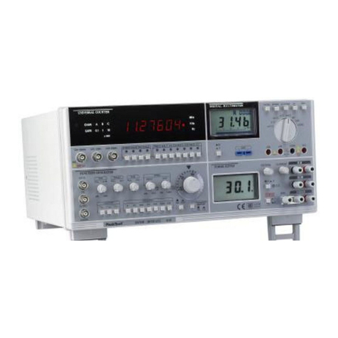
PeakTech 1135 User manual

PeakTech
®
1135
RF Vector Signal Generator
Power Supply
AC Input : @115V
H–N : 115V
H–G : 115V
N–G : <5V
Notice
- Always use the three-prong AC
Power cord supplied with this product.
- Failure to ensure adequate grounding
may cause product damage.
Operating Manual

PeakTech®1135
Read First
In order for a long period of trouble-free service of the instrument, please pay special
attention to the following precautions:
1. Protect the instrument from excessive impact during transportation and installation.
2. Be sure to verify whether the line voltage setting matches the line voltage used.
3. Use a fuse with correct ratings only.
4. Do not apply excessive AC or DC voltage to the signal output connector beyond the maximum
voltage allowed.
5. Use the instrument within operating temperature range, which is from 15 deg C to 35 deg C.
6. For an accurate measurement, allow approximately 30 minutes of instrument warm-up time.
7. Avoid operating the instrument under the following conditions; direct sun light,
rapid temperature variation, high humidity, or strong magnetic field.
8. Do not alter or change the parts or their locations inside the instrument. please contact
PeakTech®for service and calibration.
* This Information contained in this document is subject to change without Notice

PeakTech®1135
Safety Symbols
The following symbols on instrument and in the documentation indicate
precautions which must be taken to maintain safe operation of
theinstrument.
Warning
: A warning calls attention to a procedure, practice or the like which.
correctly performed or adhered to, could result in injury or loss of life.
Caution
: A Caution calls attention to a procedure, practice or the like which.
if not correctly performed or adhered to, could result in damage to
or the destruction of part or all of the equipment.
: Earth Ground to chassis
: Protective Conductor Terminal
: Frame or chassis Terminal
: Caution, risk of danger
: ON (Supply)
:OFF (Supply)

PeakTech®1135
Clearing and Maintenance
1. In order for a long period of trouble-free use of the instrument, please read
this manual carefully.
2. Be sure to verify whether the line voltage setting matches the line
voltage used. Use a fuse with the correct rating only.
3. Caution
Use 3 pin power cable to avoid any damage caused by floating voltage.
4. Precaution
Note :
If the equipment is used in a manner not specified by the manufacturer,
the protection provided by the equipment may be impaired.
- Avoid placing this instrument in an extremely hot or cold place.
- Do not use this instrument after bring it in from the cold.
- Do not expose the instrument to wet or dusty environment.
- Do not place liquid-filled container, such as coffee cups on top of this instrument
- Do not use this instrument where it is subject to serve vibration.
- Do not use this instrument in strong magnetic fields, such as near motors.
- Do not place heavy objects on the case or block the ventilation holes.
- Do not leave a hot soldering iron near the instrument.
-Cleaning:
To clean stained case, lightly rub the stained area with a soft cloth dipped in a neutral
detergent.
Never use highly volatile material such as benzene or paint thinner.

PeakTech®1135
Contents
Chapter 1 GENERAL INFORMATION
1.1 Introduction......................................................................................................................1
1.1.1 Carrier Frequency ......................................................................................................1
1.1.2 Output Level ............................................................................................................. 1
1.1.3 Digital Modulation .....................................................................................................1
1.1.4 Up-Converter Function ...............................................................................................1
1.1.5 Memory Function (Save/Recall) ................................................................................... 1
1.1.6 RS-232C .................................................................................................................. 2
1.1.7 AUTOCAL/DIAGNOSTICS........................................................................................2
1.2 Specifications .................................................................................................................... 2
1.2.1 Frequency.................................................................................................................2
1.2.2 RF Output................................................................................................................. 2
1.2.3 Spectral Purity...........................................................................................................2
1.2.4 Phase Noise @ 1000MHz............................................................................................ 2
1.2.5 Digital Modulation .....................................................................................................3
1.2.6 Up-Converter ............................................................................................................ 3
1.2.7 Front Panel Control .................................................................................................... 3
1.2.8 Interface ...................................................................................................................3
1.2.9 Appearance ...............................................................................................................3
Chapter 2 INSTALLATION INSTRUCTIONS
2.1 Introduction......................................................................................................................4
2.2 Initial Inspection................................................................................................................ 4
2.3 Electrical Installation......................................................................................................... 4
2.4 Installation Check..............................................................................................................4
2.4.1 Required Equipments.................................................................................................. 4
2.4.2 Initial Turn-On .......................................................................................................... 4
2.4.3 Test Procedure ........................................................................................................... 4

PeakTech®1135
Chapter 3 OPERATINGINSTRUCTIONS
3.1 Front Panel Description...................................................................................................... 6
3.2 Rear Panel Description....................................................................................................... 9
3.3 Operating Examples.........................................................................................................11
3.3.1 Setting of the RF Output Signal .................................................................................. 11
3.3.2 Adjusting of the RF Output Signal ..............................................................................12
3.3.3 Using of the Memory Register....................................................................................13
3.4 Initialize.......................................................................................................................... 15
Chapter 4 GPIB & RS-232C
4.1 Introduction....................................................................................................................16
4.2 Installation Instructions ................................................................................................... 17
4.3 Operating Instructions..................................................................................................... 17
4.3.1 Local/Remote Mode Selection.................................................................................... 17
4.3.2 GPIB Address Setting ............................................................................................... 17
4.3.3 GPIB & RS-232C Input Command .............................................................................17
4.3.4 Examples................................................................................................................21

PeakTech®1135
1
Chapter 1 GENERAL INFORMATION
1.1 Introduction
PeakTech®1135 is a micro-processor controlled, high frequency (10MHz~3GHz) signal
generator.
In regard of the features of PeakTech®1135, it is available to modulate external input digital
signal (I/Q) and it has the function of up-conversion.
And you can recall the memory which is stored for your convenience.
All of the control can be done at the front panel with keys and rotary knob.
The output frequency can be stepped.
1.1.1 Carrier Frequency
The operating frequency range of PeakTech®1135 is from 10MHz to 3GHz and the resolution
is 1Hz with PLL system. The LCD displays the frequency. The desired carrier frequency can
be controlled directly by key pad or rotary knob.
1.1.2 Output Level
Level can be varied from -120dBm to 0dBm in 0.1dB step.
And the flatness is under ±1.2dB.
dBm, dBuV, EMF, mV and uV can be used as its unit and also it is possible to convert each
other.
1.1.3 Digital Modulation
It is available to modulate the digital signal which is external input.
1.1.4 UP-Converter Function
The function of up-converter which mix the input IF signal with local oscillated signal so that
you can get the signal you want.
1.1.5 Memory Function (Save/Recall)
Memory registers allow you to save instruments set-ups and recall them whenever you want.
The number of the currently selected Sequence and the last Register selected are always in the
lower left corner of the display to help you keep track of where you are in your testing process.

PeakTech®1135
2
1.1.6 RS-232C
RS-232c and a computer allows programmable control of the instrument.
1.1.7 AUTOCAL/DIAGNOSTICS
PeakTech®1135 utilizes a unique AutoCal routine to perform a quick and easy, almost
completely automatic self-calibration.
1.2 Specifications
1.2.1 Frequency
-. Range : 10MHz~3GHz
-. Resolution : 1Hz (ALL BAND)
-. Frequency stability/Temp : ±0.05ppm, 0 ~40 , OCXO
-. Frequency stability (time) : < 2 ppm/yr.
1.2.2 RF Output
-. Impedance : 50
( VSWR < 1.5:1 for output<- 4dBm )
-. Output connector : Type "N"
-. Calibrated Level Range : 0 to -120dBm
-. Level Resolution : 0.1dB
-. ATT Accuracy : ±1.0dB (-30dBm to 0dBm)
±2.0dB(-120dBm to -30dBm)
-. Flatness : ±1.2dB (±0.7dB, typical) at 0dBm
-. EMI/RFI Leakage : < 1uV into a 2-turn 1 inch diameter
loop 1 inch from any surface at 1000MHz
1.2.3 Spectral Purity
-. Harmonics : <-30dBc
1.2.4 Phase Noise @ 1000MHz
-. 10kHz offset : -95dBc/Hz

PeakTech®1135
3
1.2.5 Digital Modulation
-. Mode : I/Q
-. External Source
InputLevel :1Vpp
Input impedance : 50
1.2.6 UP-Converter
-. Mode : IF
-. External Source
Input Frequency : 70MHz, 36MHz (Option : 44MHz)
Input Level : 0 ~ -20dBm
Input Impedance : 50
1.2.7 Front Panel Control
-. Type : Push-buttons, Rotary-knob,
RS-232C , GPIB
1.2.8 Interface
- RS-232C ( Standard ), GPIB ( Option )
1.2.9 Appearance
-. Dimensions : 115(H) × 430(W) × 490(D)mm
-. Weight : 13kg ( Except package box, Accessory...)
-. Power : 90 ~ 230VAC, 50/60Hz, 90VAmax
-. Standard Accessories : Power Cable
Cable (N-N) , Cable ( BNC-BNC ) – 2 ea
Operating Manual, Fuse
-. Others : Indoor use
Amplitude up to 2000 m
Pollution degree IP20

PeakTech®1135
4
Chapter 2 INSTALLATION INSTRUCTIONS
2.1 Introduction
This chapter provides complete installation instruction for PeakTech®1135. The instruction
includes the initial inspection, the precautions for AC line connection, and the equipment turn-
on procedures.
2.2 Initial Inspection
Open the package, inspect for any mechanical damage to the product; e.g., instrument exterior,
connectors, and so on.
2.3 Electrical Installation
The equipment operates on 50/60Hz, 90~230V AC line voltages.
1.0A fuse for 90~230V operation is used.
2.4 Installation Check
Although every PeakTech®1135 is checked carefully before each shipment, some chance still
exists for equipment damage during transportation. Therefore, the operator should verify
whether the received equipment is correct or not. The following installation instruction provides
the verification procedure.
2.4.1 Required Equipments
In order to test the operation of PeakTech®1135, one needs to verify the output frequency and
power level requiring spectrum analyzer and power meter.
2.4.2 Initial Turn-On
When the power switch is pushed on, the front panel display will indicate the operation of the
instrument.
2.4.3 Test Procedure
The following paragraphs describe the general operational test procedures for PeakTech®1135.
Please verify with test equipments that have proper specification.

PeakTech®1135
5
2.4.3.1 Frequency
Verify that frequency commanded with keypad or rotary knob is correct.
Modulation: OFF, RF Level: 0dBm
2.4.3.2 Output Level
Verify that output level commanded with keypad or rotary knob is correct.
Modulation = OFF, Frequency=1000MHz, RF Level = 0dBm
2.4.3.3 Digital Modulation ( I/Q )
Set RF Level =-10dBm , Frequency = 1000MHz, MODE = IQ . MOD = ON
If any IQ source don't be supplied to this equipment , the output signal is generated as follow.
Level : ( -10 - 20) dBm = -30dBm ( Approximately )
2.4.3.4 UP-Converter
Set RF Level =-10 dBm , Frequency = 1000MHz, MODE = IF, MOD = ON
If any IF source don't be supplied, the output signal is generated as follow.
Level : (-10 -20) dBm = -30dBm ( Approximately )

PeakTech®1135
6
Chapter 3 OPERATING INSTRUCTIONS
3.1 Front Panel Description
1. I ( IN-phase ) , Q ( Quadrature ) Input Terminal
2. DISPLAY
The Display shows the information of the state of PeakTech®1135 such as modulation, frequency
and amplitude etc.
If nothing is displayed, please check the illumination of the display.
3. (FREQ) key
Press this key to activate the frequency function so that you can change the frequency of the
RF output EX) How to use
1) Press (FREQ) key
2) Press the value you want
3) Press Unit Set key (Hz, kHz, MHz)
If the value is out of the frequency range of PeakTech®1135 (10MHz ~ 3GHz), it returns
to its former value.
4. (LEVEL) key
Press this key to activate the level function so that you can change the amplitude of the RF
output.
EX) How to use
1) Press (LEVEL) key
2) Press the value you want

PeakTech®1135
7
3) Press Unit Set key (uV, mV, dBm)
If the value is out of the output level range of DSG-3000 (-120dBm ~ 0dBm), it returns to
its former value.
5. (IQ) key (In-Phase Quadrature-Phase)
Press this key to modulate the signal with the external I/Q signal.
6. (CW) key
Press this key to get the wanted output signal without any modulation.
7. (IF) key (Intermediate Frequency)
It is possible to up-convert the external IF signal.
8. (STEP) key
Press this key to set up the increment value of frequency or level.
9. (MEMORY) key
Press this key to store the current set value to the register or to recall the stored value of the
register.
EX1) How to store the value
1) Press (FCN) key
2) Press (MEMORY) key
3) Input the address you want with the numeric key ( 00 ~ 99)
EX2) How to recall the value
1) Press (MEMORY) key
2) Press the address( 00 ~ 99) you want to recall
If there is nothing is the address you pressed, a message appear on the display.
10. (FCN) key
This key is used with another key to operate a function
Initialize : (FCN) key , key
DEL : (FCN) key , key
CALIBRATION : (FCN) key , key
GPIBAddress : (FCN) key , . (FREQ) key

PeakTech®1135
8
11. Numeric Keypad
The numeric keys are used when you input the data by number.
12. Back Space key
Press this key if you want to revise or delete the wrong number when you input the value.
13. Unit Set keys
You can choose the unit of frequency and level for your convenience.
Setting of Frequency : (MHz), (kHz) , (Hz)
Setting of Level : (dBm), (mV), (uV)
Note] How to setting ( dBuV, dBuV EMF)
Press (FCN) key , (MHz) key
14. , key
The left and right arrow keys choose the under cursor digit in the active
15. , key
The up and down arrow keys increase or decrease a numeric value by step setting value.
16. (RF ON/OFF) key
This key is used to turn on or off the RF signal of the RF output terminal.
And it is available to Cancel the function of Tripped of Reverse Power Protection with this RF
ON/OFF key.
17. (MOD ON/OFF ) key
You can set up the condition of RF signal whether you use the function of modulation or not.
Although you can set up the value and condition of modulation, the RF carrier is not modulated
until MOD ON/OFF is set to ON.
You can check the condition of MOD ON/OFF on the display whether the function of modulation is
turned on or off.
* It is not available to use this key in case of "CW"
18. (SWEEP) key
This key is used for the function of sweep of frequency or level.
Frequency sweep : Press (SWEEP) key, . (FREQ) key

PeakTech®1135
9
Level sweep : Press (SWEEP) key, . (LEVEL) key
19. ( SWEEP ON/OFF ) key
You can start of stop the function of sweep with this key.
20. (KNOB ) key
The knob increases or decreases a numeric value of cursor position.
Any of the values that can be set through the numeric keypad can also be set with the knob.
21. (STBY) key
If the system is ready, the LED of STBY is on. After the ready, if the system works, the LED is off.
22. (LOCAL) key
Press this key, if you want to control the instrument with front panel, when the instrument is
being controlled by remote (RS-232C, GPIB).
23. RF Output terminal
This N-type connector is the terminal of RF signal output.
3.2 Rear Panel Description
1. RS-232c connector
2. GPIB connector ( Option 1)
3. 10MHz Output Terminal
4. IF Input Terminal
It is available to input the IF signal of 70MHz or 36MHz.

PeakTech®1135
10
5. Power ON/OFF switch ( 90~ 230 VAC )
PeakTech®maintains the last setting condition before turning off.
Caution
Please keep the interval of two seconds at least between on and off to prevent the
instrument from being damaged due to the surge current.
6. Fan

PeakTech®1135
11
3.3 Operating Examples
3.3.1 Setting of the RF Output Signal
In the following example, you can show the way of setting of frequency, level and modulation
of RF output signal.
[ The start display ]
FREQ 1000.000000 MHz MOD RF
LEV -107 dBm OFF OFF
MODE CW
MEM REG - -
3.3.1.1 Setting of Frequency (ex. : 2000MHz)
Press these keys : (FREQ) , , , , , (MHz)
FREQ 2000.000000 MHz MOD RF
LEV -107 dBm OFF OFF
MODE CW
MEM REG - -
3.3.1.2 Setting of Level ( ex: -30dBm)
Press these keys : (LEVEL) ,, , , (dBm)
FREQ 2000.000000 MHz MOD RF
LEV -30.0 dBm OFF OFF
MODE CW
MEM REG - -
3.3.1.3 Turn on the RF output
Press the (RF ON/OFF )key to turn on the RF output
FREQ 2000.000000 MHz MOD RF
LEV -30.0 dBm OFF ON
MODE CW
MEM REG - -
If the RF output is off, ' RF OFF ' appear on the display

PeakTech®1135
12
3.3.1.4 Setting of digital modulation (ex. : IQ on, MOD on)
Press these keys : (IQ) , (MOD ON/OFF)
FREQ 2000.000000 MHz MOD RF
LEV -30.0 dBm ON ON
MODE IQ EXT AC
MEM REG - -
3.3.1.5 Setting of the Up-convert function (ex. : IF on)
Press these keys : (IF) , (MOD ON/OFF)
FREQ 2000.000000 MHz MOD RF
LEV -30.0 dBm ON ON
MODE IF EXT AC
MEM REG - -
3.3.2 Adjusting of the RF Output Signal
3.3.2.1 Preliminary steps
Set the frequency to 1000MHz and level (amplitude) to 0dBm.
The cursor in on the level.
FREQ 1000.000000 MHz MOD RF
LEV 0.0 dBm ON ON
MODE IF EXT AC
MEM REG - -
3.3.2.2 Using of knob
Decrement the amplitude by using of the knob.
FREQ 1000.000000 MHz MOD RF
LEV 0.0 dBm ON ON
MODE IF EXT AC
MEM REG - -
Press or when you want to adjust the increment resolution.

PeakTech®1135
13
3.3.2.3 Using of (STEP) function ( ex: FREQ INCrement STEP= 25kHz )
1) Press these keys: (FREQ) , (STEP), , , (kHz)
(Setting of the step)
FREQ 25.000 kHz MOD RF
LEV 0.0 dBm ON ON
MODE IF EXT AC
MEM REG - -
2) Press this key : (FREQ) key
(Return to the main display)
FREQ 1000.000000 MHz MOD RF
LEV 0.0 dBm ON ON
MODE IF EXT AC
MEM REG - -
3) Press the (or )key
(Control the output frequency by step)
FREQ 1000.025000 MHz MOD RF
LEV 0.0 dBm ON ON
MODE IF EXT AC
MEM REG - -
3.3.3 Using of the Memory Register
3.3.3.1 Store the setting data of PeakTech®1135 to the register.
1) Press these keys : (FCN) , (MEMORY)
FREQ 1000.025000 MHz MOD RF
LEV 0.0 dBm ON ON
MODE IF EXT AC
MEM SAVE - - 100 available
If there is not any data in the register, the above message appears on the display.

PeakTech®1135
14
2) Store the above setting data to register memory 5
Press these keys : ,
FREQ 1000.025000 MHz MOD RF
LEV 0.0 dBm ON ON
MODE IF EXT AC
MEM REG 05 saved
FREQ 1000.025000 MHz MOD RF
LEV 0.0 dBm ON ON
MODE IF EXT AC
MEM REG 05
3) Store the following data to register memory 4
ex) Frequency : 2000 MHz
Level :-33dBm
3.3.3.2 Recall the data of register memory 5.
1) Press these keys : ( MEMORY) , ,
FREQ 2000.000000 MHz MOD RF
LEV -33.0 dBm ON ON
MODE IF EXT AC
MEM REG 04
FREQ 1000.025000 MHz MOD RF
LEV 0.0 dBm ON ON
MODE IF EXT AC
MEM REG 05
Table of contents
Other PeakTech Laboratory Equipment manuals