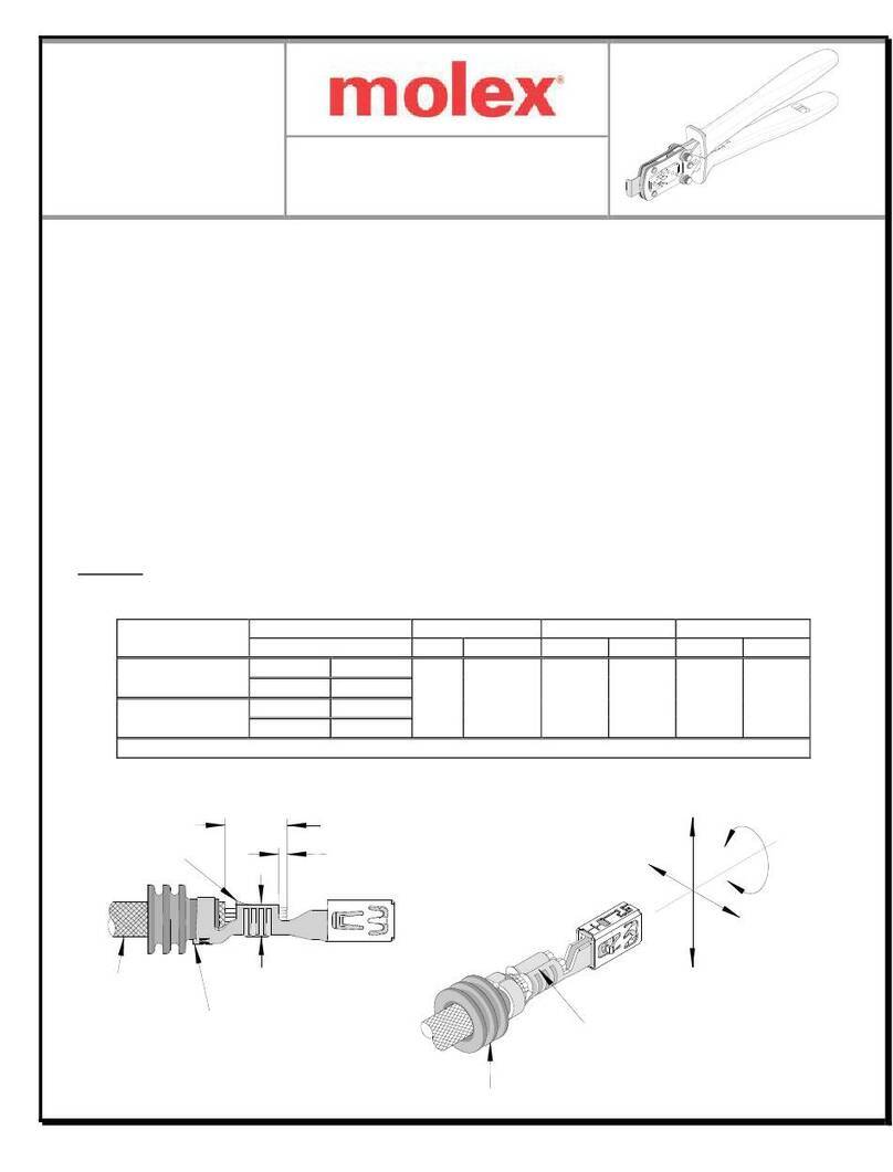
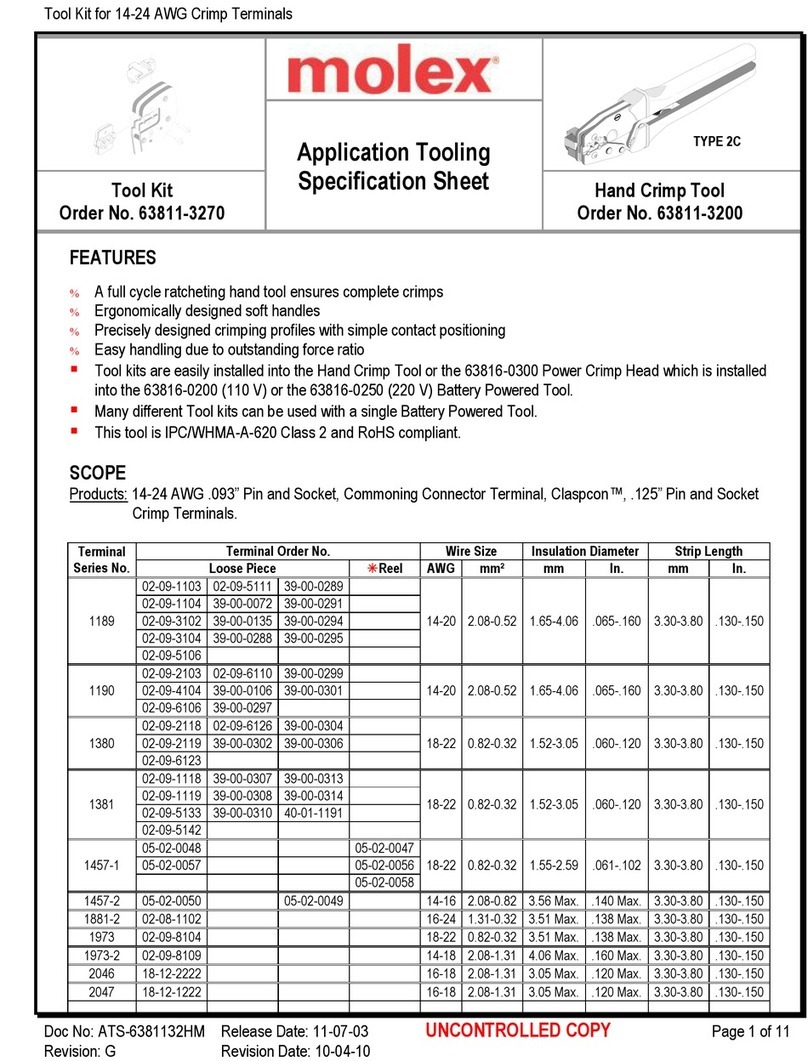
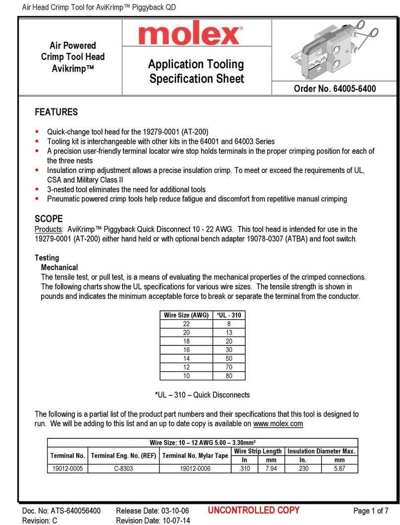
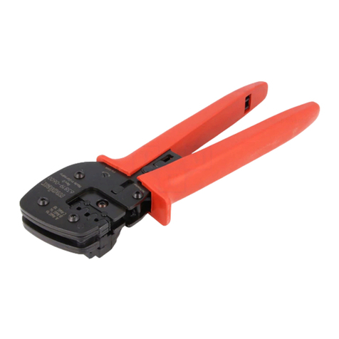
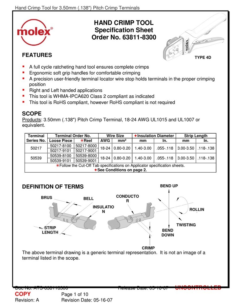
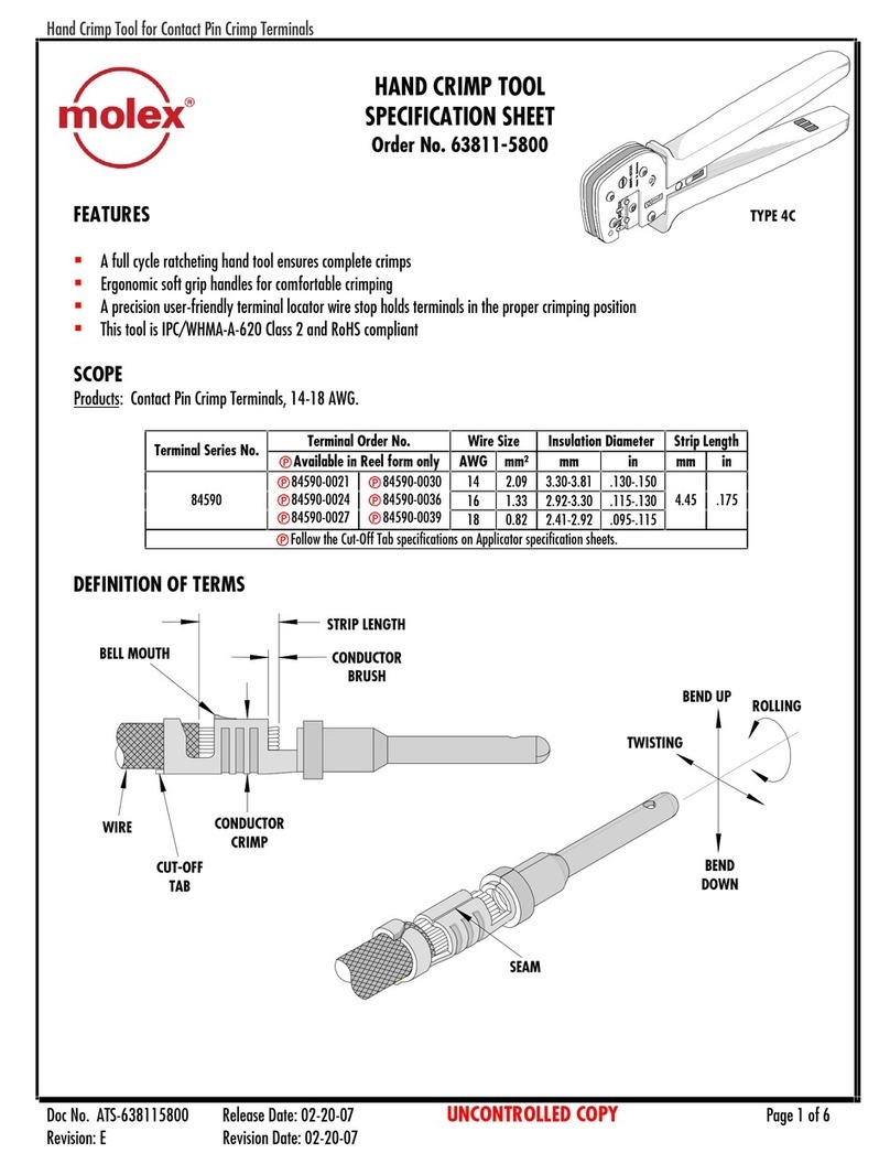
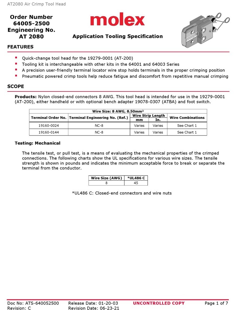
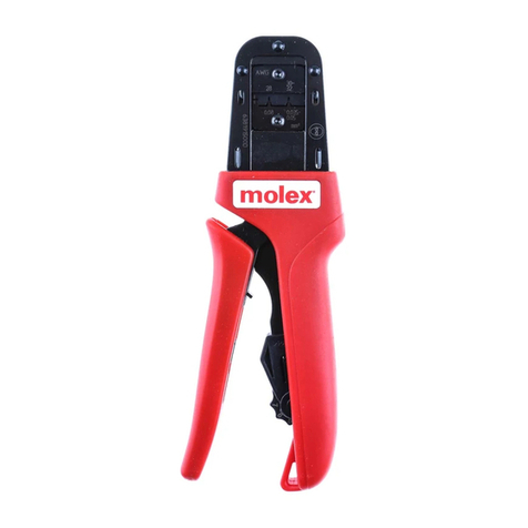
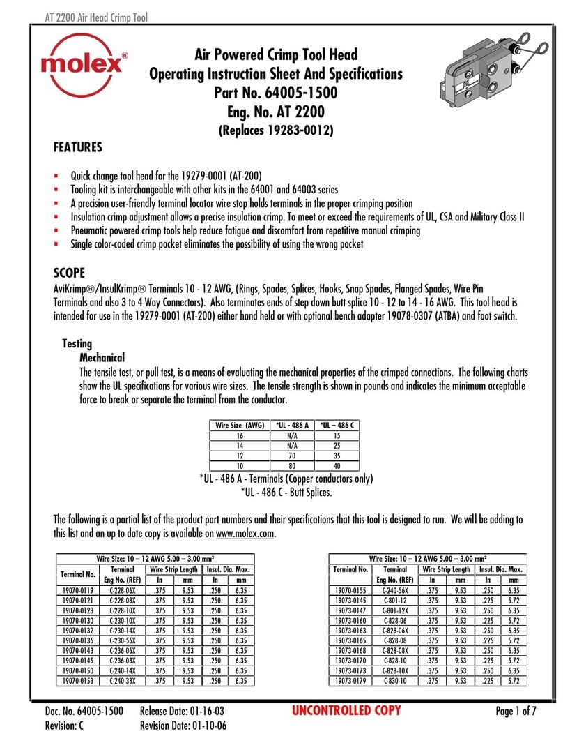
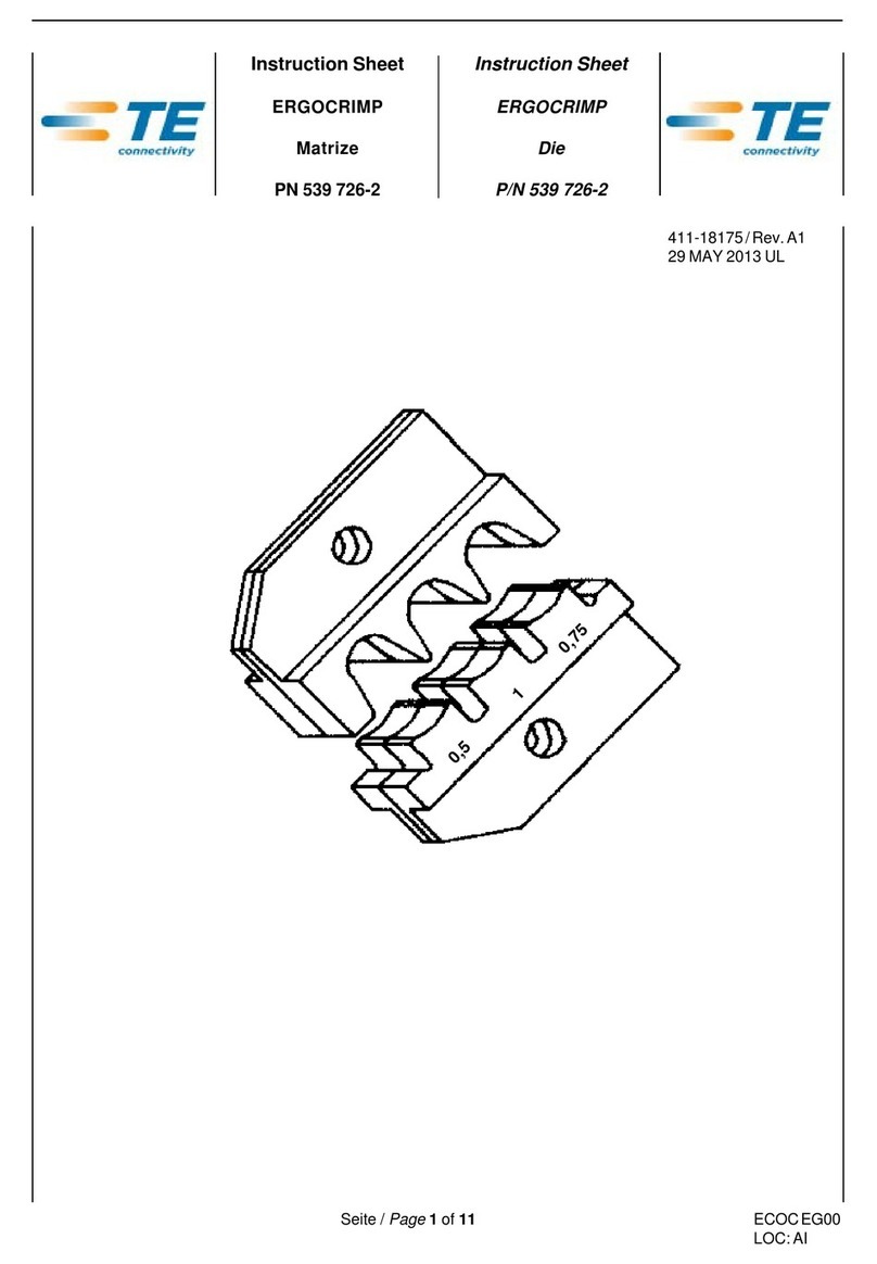
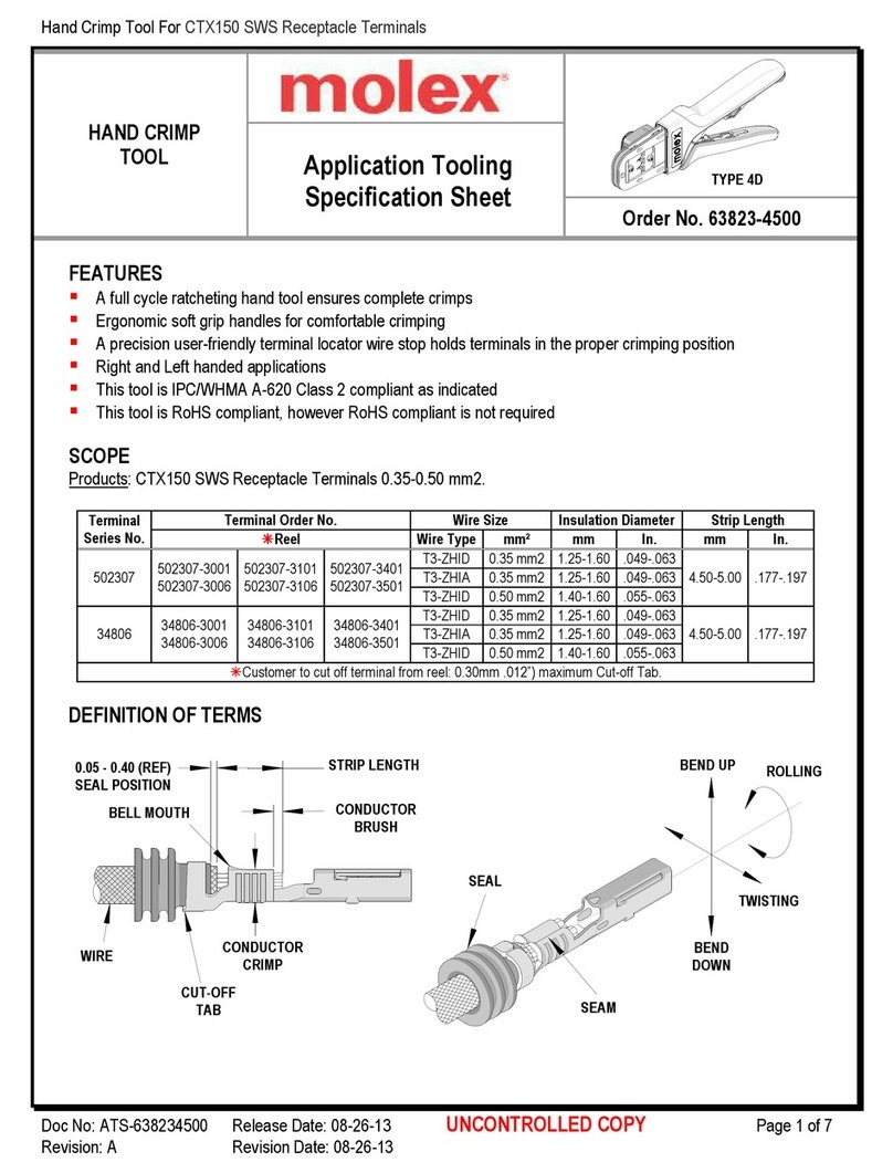
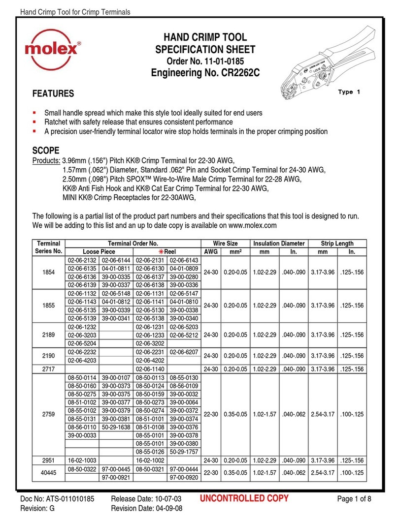
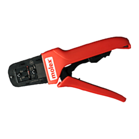
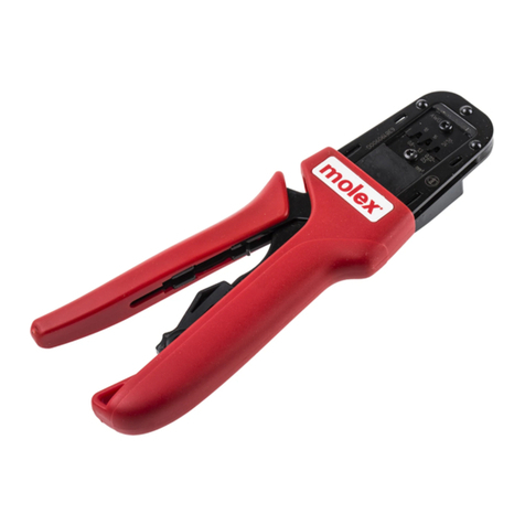
molex 50098 Series User manual

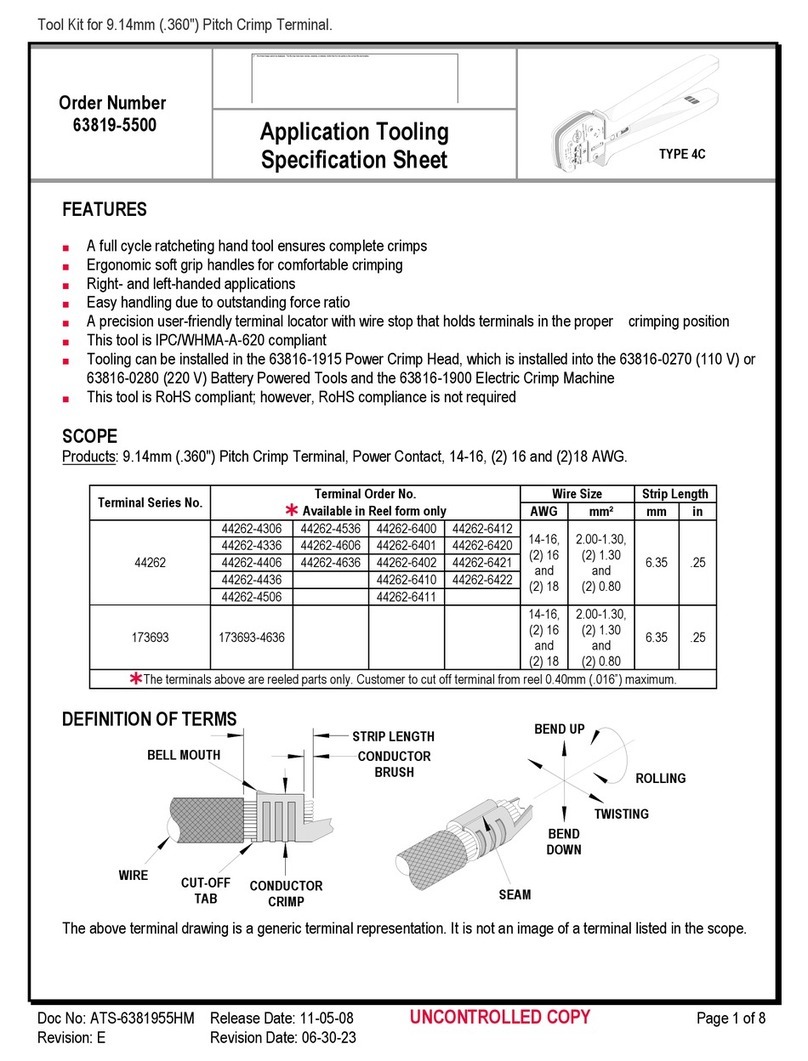
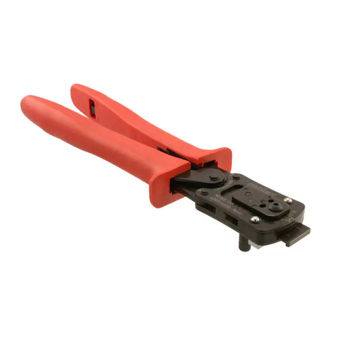
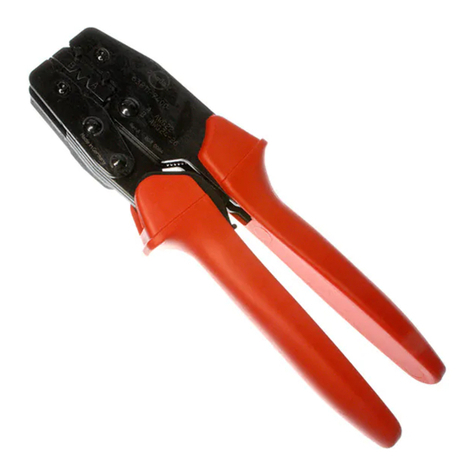
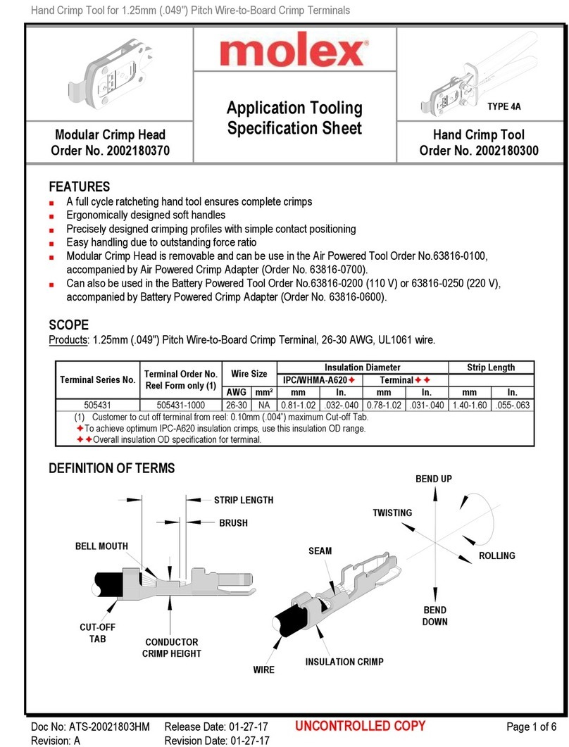
Hand Crimp Tool for Board-In Crimp Terminals
Doc No: ATS-6382366HM Release Da e: 02-23-11 UNCONTROLLED COPY Page 1 of 7
Revision: A Revision Da e: 02-23-11
Application Tooling
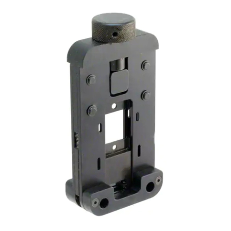
Specification Sheet
Modular Crimp ead
Order No. 63823-6670
and Crimp Tool
Order No. 63823-6600
FEATURES
% A full cycle ra che ing hand ool ensures comple e crimps
% Ergonomically designed sof handles
% Precisely designed crimping profiles wi h simple con ac posi ioning
% Easy handling due o ou s anding force ra io
% Modular Crimp Head is removable and can be use in he Air Powered Tool Order No.63816-0100,
accompanied by Air Powered Crimp Adap er (Order No. 63816-0700).
% Can also be used in he Ba ery Powered Tool Order No.63816-0200 (110 V) or 63813-0250 (220 V),
accompanied by Ba ery Powered Crimp Adap er (Order No. 63816-0600).
SCOPE
Produc s: 4.00mm (.157”) Pi ch Board-In Crimp Terminal, 18-22 AWG, 0.85mm²; o 0.30mm² me ric wire.
Terminal
Series
Terminal Order No. Wire Size Insulation Diameter Wire Strip Length
Reel Loose Wire Style mm² / AWG mm In. mm In.
50098 50098-8000 50098-8100
18
1.6-2.6 .063-.102 2.50-3.00 .098-.118
20
22
AVS 0.85
AVS 0.50
AVS 0.30
AV 0.85
AV 0.50
AV 0.75f
AV 0.50f
Cus omer o cu off erminal from reel: 0.20mm (.008”) maximum Cu -off Tab.
See crimp specifica ion for he individual Insula ion Diame er.
TYPE 4A

Hand Crimp Tool for Board-In Crimp Terminals
Doc No: ATS-6382366HM Release Da e: 02-23-11 UNCONTROLLED COPY Page 2 of 7
Revision: A Revision Da e: 02-23-11
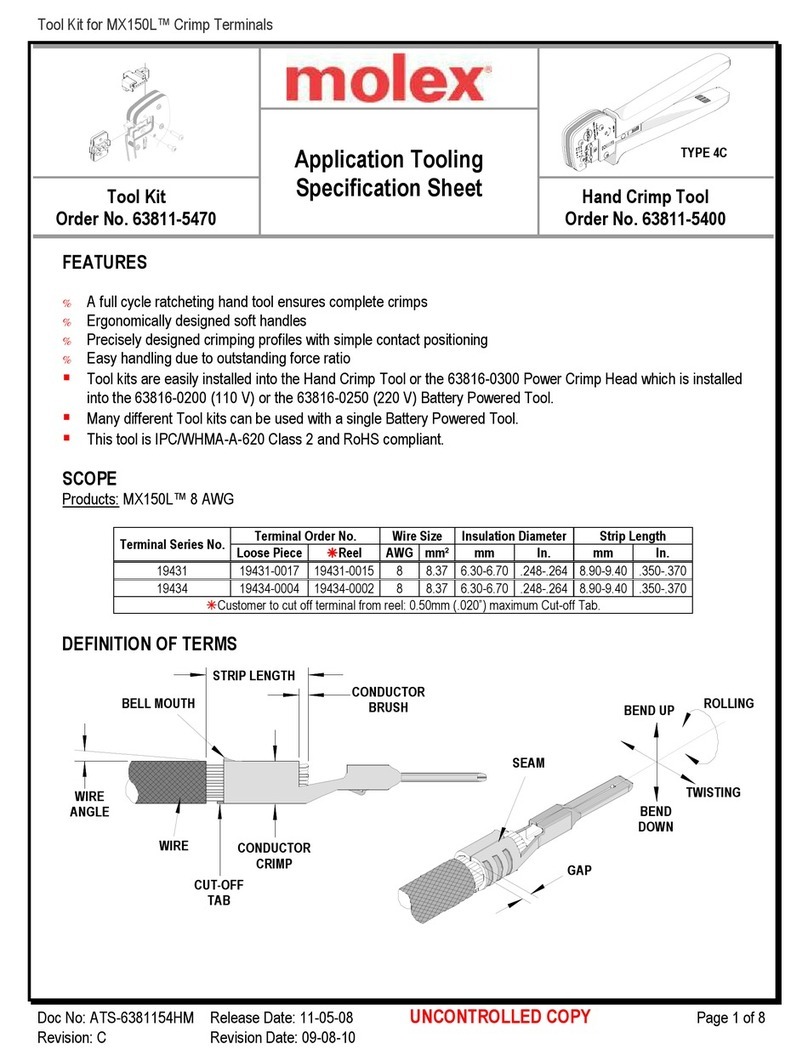
DEFINITION OF TERMS
This illus ra ion is a generic erminal represen a ion and no an exac image of any erminal lis ed in he scope.
▲Insulation Crimp Note:
Due o he erminal’s insula ion grip design and/or
insula ion diame er range, his ool uses “overlap”
form geome ry in he insula ion punch. This produces
an overlap insula ion crimp (A620 – complian ).
While he insula ion punch profile may appear
“lopsided”, his is a normal condi ion for his ool. See
figure o he righ . (Some ools wi h mul iple crimp
pocke s may no have he “overlap” profile on all
pocke s).
CRIMP SPECIFICATIONS:
Af er crimping, he crimp profiles should measure he following.
Terminal
Series No.
Wire Size Conductor Crimp Profile
eight Width (Ref.)
Wire Style mm² / AWG mm In. mm In. 18awg
.75-.85mm
20awg
.50mm
22awg
.30mm
50098
18 1.12-1.22
.044-.048
1.65 .065 X
20 0.93-1.03
.037-.041
1.65 .065 X
22 0.87-0.92
.034-.036
1.65 .065 X
AVS 0.85 1.12-1.22
.044-.048
1.65 .065 X
AVS 0.50 0.96-1.06
.038-.042
1.65 .065 X
AVS 0.30 0.91-0.96
.036-.038
1.65 .065 X
AV 0.85 1.14-1.24
.045-.049
1.65 .065 X
AV 0.50 0.96-1.06
.038-.042
1.65 .065 X
AV 0.75f 1.07-1.17
.042-.046
1.65 .065 X
AV 0.50f 0.93-1.03
.037-.041
1.65 .065 X
INSULATION
CRIMP
▲SEE NOTE
BRUS
STRIP
LENGT
BELL MOUT
COND.CRIMP
EIG T
BEND
DOWN
BEND UP
ROLLING
CONDUCTOR
CRIMP
TWISTING
CUT-OFF TAB
SEAM
OVERLAP
INSULATION
CRIMP
OVERLAP FORM GEOMETRY
ANVIL
PUNC
WIRE

Hand Crimp Tool for Board-In Crimp Terminals
Doc No: ATS-6382366HM Release Da e: 02-23-11 UNCONTROLLED COPY Page 3 of 7
Revision: A Revision Da e: 02-23-11
WIRE
CONDUCTOR
PUNC
TERMINAL
WIRE STOP
BLADE
Figure 2
Terminal
Series No.
Wire Size Insulation Diameter
Insulation Crimp Pull Force
Minimum
eight (Ref.)
Width (Ref.)
Wire Style
mm² / AWG
mm In. mm In. mm In. N Lb.
50098
18 2.0-2.2 .079-.087 2.20 .087 2.75 .108
88.0
19.78
20 1.7-1.8 .067-.071 1.90 .075 2.75 .108
58.7
13.20
22 1.6-1.7 .063-.067 1.95 .077 2.30 .091
39.1
8.79
AVS 0.85 2.2-2.3 .087-.091 2.20 .087 2.75 .108
88.0
19.87
AVS 0.50 2.0-2.0 .079-.083 2.00 .079 2.75 .108
58.7
13.20
AVS 0.30 1.8-1.9 .071-.075 1.95 .077 2.30 .091
39.1
8.79
AV 0.85 2.4-2.6 .094-.102 2.20 .087 2.75 .108
88.0
19.78
AV 0.50 2.2-2.4 .087-.094 2.05 .081 2.75 .108
58.7
13.20
AV 0.75f 2.4-2.6 .094-.102 2.20 .087 2.75 .108
88.0
19.78
AV 0.50f 2.2-2.4 .087-.094 2.05 .081 2.75 .108
58.7
13.20
Tool Qualification Notes:
1. Pull Force should be measured wi h no influence from he
insula ion crimp.
2. The above specifica ions are guidelines o an op imum
crimp.
OPERATION
Open he ool by squeezing he handles oge her, a he end of
he closing s roke, he ra che mechanism will release he
handles, and he hand ool will spring open.
Crimping Terminals
1. Wi h he hand ool in he open posi ion, pivo he erminal
loca or open by pulling up on he loca or knob and lif he
wire s op blade up. See Figure 1.
2. Inser he erminal in o he correc profile un il he erminal is fully sea ed and s ops. Make sure he wire
s op blade is fully sea ed on he erminal behind he
conduc or grip sec ion.
3. Gen ly pivo he loca or closed.
4. Bring down he wire s op blade.
5. Slide he pre-s ripped wire in o he erminal; make sure o
aim he wire brush owards he ip poin on he wire s op
blade. See Figure 2. Align he wire so ha i is parallel and
si ing in o he erminal. Main ain a ligh and cons an
pressure on he wire ha is sea ed in he erminal a all
imes. (Do no le go of he wire.) Be sure o hold he wire
and erminal in place un il he erminal is fully crimped. See
Figure 3.
6. Close he ool un il he ra che releases.
7. Lif he wire s op blade up.
8. Carefully remove he crimped erminal.
Note: The amper proof ra che ac ion will no release he ool un il i has been fully closed.
TERMINAL
SEATED IN
LOCATOR
LOCATOR
OPEN
Figure 1
AND TOOL
OPEN

Hand Crimp Tool for Board-In Crimp Terminals
Doc No: ATS-6382366HM Release Da e: 02-23-11 UNCONTROLLED COPY Page 4 of 7
Revision: A Revision Da e: 02-23-11
INCORRECT
Figure 5
CORRECT INCORRECT
WIRE
CONDUCTOR
PUNC
WIRE STOP
BLADE
INSULATION
PUNC
LOCATOR
CONDUCTOR ANVIL
INSULATION
ANVIL
TERMINAL
Figure 3
Note: To main ain good brush con rol and a consis en bell mou h he crimping ins ruc ions mus be followed.
Terminal Locator Replacement/Change Over
This sec ion describes he procedure for changing loca ors.
Removal
1. Wi h he ool in he open posi ion, pivo he erminal
loca or ou ward.
2. Remove he M4 BHCS. See Figure 4.
Installation
1. Place he proper loca or, on he hand ool. Ins all he M4 BHCS. See Figure 4.
2. Tigh en he screw enough o hold he loca or. Make sure he loca or can s ill floa freely wi h hand pressure.
3. Inser he proper erminal fully in o he correc profile slo un il he erminal is fully sea ed and s ops. Then
gen ly pivo he loca or closed.
4. Wi h hand pressure, slowly slide he loca or o he correc posi ion. See Figure 5.
5. Gen ly pivo he loca or open wi hou dis urbing he loca ion.
6. Hold he loca or firmly in place and slowly igh en he M4 BHCS.
Maintenance
I is recommended ha each opera or of he ool be made aware of, and responsible for, he following
main enance s eps:
1. Remove dus , mois ure, and o her con aminan s wi h a clean brush, or sof , lin free clo h.
2. Do no use any abrasive ma erials ha could damage he ool.
M4 B CS
PIVOT LOCATOR
Figure 4

Hand Crimp Tool for Board-In Crimp Terminals
Doc No: ATS-6382366HM Release Da e: 02-23-11 UNCONTROLLED COPY Page 5 of 7
Revision: A Revision Da e: 02-23-11
3. Make cer ain all pins; pivo poin s and bearing surfaces are pro ec ed wi h a hin coa of high quali y machine
oil. Do no oil excessively. The ool was engineered for durabili y bu like any o her equipmen i needs
cleaning and lubrica ion for a maximum service life of rouble free crimping. Ligh oil (such as 30 weigh
au omo ive oil) used a he oil poin s, every 5,000 crimps or 3 mon hs, will significan ly enhance he ool life.
4. Wipe excess oil from hand ool, par icularly from crimping area. Oil ransferred from he crimping area on o
cer ain ermina ions may affec he elec rical charac eris ics of an applica ion.
5. When ool is no in use, keep he handles closed o preven objec s from becoming lodged in he crimping dies,
and s ore he ool in a clean, dry area.
Miscrimps or Jams
Should his ool ever become s uck or jammed in a par ially closed posi ion, Do Not force he handles open or
closed. The ool will open easily by lif ing he ra che release lever. See Figure 6.
Warranty
This ool is for elec rical erminal crimping purposes only. This ool is made of he bes quali y ma erials. All vi al
componen s are long life es ed. All ools are warran ed o be free of manufac uring defec s for a period of 30
days. Should such a defec occur, we will repair or exchange he ool free of charge. This repair or exchange will
no be applicable o al ered, misused, or damaged ools. This ool is designed for hand use only. Any clamping,
fix uring, or use of handle ex ensions voids his warran y.
CAUTION: Repe i ive use of his ool should be avoided.
CAUTIONS:
1. Manually powered hand ools are in ended for low volume or field repair. This ool is NOT in ended for
produc ion use. Repe i ive use of his ool should be avoided.
2. Insula ed rubber handles are no pro ec ion agains elec rical shock.
3. Wear eye pro ec ion a all imes.
4. Use only he Molex erminals specified for crimping wi h his ool.
Notes:
1. This ool should only be used for he erminals and wire gauges specified on his shee .
2. This ool is no adjus able for crimp heigh , however crimp force is adjus able (See ins ruc ions above).
Varia ions in ools, erminals, wire s randing and insula ion ypes may affec crimp heigh .
3. This ool is in ended for s andard conduc or sizes. I may no give a good insula ion crimp suppor for all
insula ion sizes.
4. Molex does no repair hand ools (see warran y above). The replacemen par s lis ed are he only par s
available for repair. If he handles or crimp ooling is damaged or worn, a new ool mus be purchased.
5. Pull force should be used as he final cri eria for an accep able crimp. Pull force is measured wi h no
influence from he insula ion crimp. The insula ion should be s ripped long (1/2 in.) so he insula ion grips
on he erminal do no grip he wire insula ion or he conduc or. Refer o Molex Quali y Crimping
Handbook 63800-0029 for addi ional informa ion on crimping and crimp es ing.
6. Molex does no cer ify crimp hand ools.
CAUTION: Molex crimp specifica ions are valid only when used wi h Molex erminals and ooling.
Hand Crimp Tool for Board-In Crimp Terminals
Doc No: ATS-6382366HM Release Da e: 02-23-11 UNCONTROLLED COPY Page 6 of 7
Revision: A Revision Da e: 02-23-11
MODULAR
CRIMP
EAD
BATTERY
POWER
CRIMP
ADAPTER
LOCKING
PINS
LOCKING PINS
BATTERY
POWERED
TOOL
AIR
POWER
TOOL
MODULAR
CRIMP EAD
LOCKING
PINS
LOCKING
PINS
AIR
POWER
CRIMP
ADAPTER
Applications for the Modular Crimp ead
WARNING: NEVER opera e, service, ins all, or adjus his Modular Crimp Head wi hou proper ins ruc ion
and wi hou firs reading and unders anding he ins ruc ions in he proper Manual or Specifica ion Shee .
See Char below for he correc Manual or Specifica ion Shee .
WARNING: NEVER ins all ooling or service his ool while i is in o any power source. Disconnec he
power by unplugging or urn off he Ac ua or from i s power source.
CAUTION: Keep fingers away from he crimping area when opera ing his ool. I may cause severe injury.
CAUTION: Wear safe y glasses when opera ing or serving his ool.
The char below shows all applica ions for his Modular Crimp Head.
Modular Crimp ead
Order No.
Tool
Order no.
Tool
Description
Adapter
Order No.
Adapter
Description Figure No.
63823-6670
63816-0000
Hand Crimp Frame (Shor ) N/A N/A 3
63816-0050
Hand Crimp Frame (Long) N/A N/A 3
63816-0200
Ba ery Power Tool (110 V)
63816-0600
Ba ery Power Crimp Adap er
4
63816-0250
Ba ery Power Tool (220 V)
63816-0600
Ba ery Power Crimp Adap er
4
63816-0100
Air Power Tool 63816-0700
Air Power Crimp Adap er 5
Applications for the Modular Crimp ead
and Crimp Tool Battery Powered Tool Air Powered Tool
Figure 6 Figure 7 Figure 8
MODULAR
CRIMP
EAD
LOCKING
PINS
AND CRIMP
FRAME LONG
OR S ORT

Hand Crimp Tool for Board-In Crimp Terminals
Doc No: ATS-6382366HM Release Da e: 02-23-11 UNCONTROLLED COPY Page 7 of 7
Revision: A Revision Da e: 02-23-11
RATC ET
RELEASE LEVER
ANDLE
SPRING
CRIMPING
SPRING (2)
LOCATOR
2
1
Figure 9
M4 X 6mm
LONG B CS
3
4
6
5
PARTS LIST
and Crimp Tool 63823-6600
Item
Order Number
Description Quantity
1 63823-6670 Modular Crimp Head 1 (Ref)
2 63816-0050 Hand Crimp Frame (Shor )
1 (Ref)
3 63823-6675 Loca or 1
4 63816-0001 Locking Pin 2
5 63600-0525 Handle Spring 1
6 63600-0520 Crimping Spring 2
h p://www.molex.com
This manual suits for next models
4
Table of contents
Other molex Crimping Tools manuals

molex
molex 35465 Series User manual

molex
molex 207129 Series User guide

molex
molex 207129 Series User manual

molex
molex CS 150 User manual

molex
molex 207129 Series User manual

molex
molex 63827-0600 User manual

molex
molex 64005-6200 User manual

molex
molex CR5907 User manual

molex
molex 50837 User manual

molex
molex 64001-1000 User manual

molex
molex 207129 Series User manual

molex
molex ServiceGrade User guide

molex
molex 19294-0008 User manual

molex
molex 63819-3800 User manual

molex
molex 98897 User manual

molex
molex 63825-9900 User manual

molex
molex 64001-5900 User manual

molex
molex 63825-4970 User manual

molex
molex 207129 Series User manual

molex
molex 207129 Series User manual