molex 64001-8800 User manual

Tool Kit for AviKrimpFully Insulated and-Insulated Quick Disconnect Flags
Doc No: ATS-6400188HM Release Date: 04-08-15 UNCONTROLLED COPY Page 1 of 9
Revision: B Revision Date: 06-17-15
Application Tooling
Specification Sheet
Tool Kit
Order No. 64001-8870
Hand Crimp Tool
Order No. 64001-8800
FEATURES
A full cycle ratcheting hand tool ensures complete crimps
Ergonomically designed soft handles
Precisely designed crimping profiles with simple contact positioning
Easy handling due to outstanding force ratio
Tool kits are easily installed into the Hand Crimp Tool or the 63816-0300 Power Crimp Head which is installed
into the 63816-0200 (110 V) or the 63816-0250 (220 V) Battery Powered Tool.
Many different Tool kits can be used with a single Battery Powered Tool.
SCOPE
Products: AviKrimpFully Insulated and-Insulated Quick Disconnect Flags 10-12 AWG.
Testing
Mechanical
The tensile test or pull test is a means of evaluating the mechanical properties of the crimped connections. The
following chart shows the UL specifications for various wire sizes. The tensile strength is shown in pounds and
indicates the minimum acceptable force to break or separate the terminal from the conductor.
Wire Size (AWG)
*UL - 310
12
70
10
80
*UL –310 –Quick Disconnects
CONDITIONS:
The following is a partial list of the product part numbers and their specifications that this tool is designed to
crimp. We will be adding to this list and an up to date copy is available on www.molex.com.
Wire Size: 10 –12 AWG 5.00 –3.30 mm²
Terminal No.
Terminal Eng. No. (REF)
Wire Strip Length
Insulation Diameter Maximum
In.
mm
In.
mm
19006-0019
C-5211
.344
8.73
.245
6.22
19007-0040
C-2211
.344
8.73
.260
6.60
19007-0082
C-2211V
.344
8.73
.260
6.60
TYPE 4C

Tool Kit for AviKrimpFully Insulated and-Insulated Quick Disconnect Flags
Doc No: ATS-6400188HM Release Date: 04-08-15 UNCONTROLLED COPY Page 2 of 9
Revision: B Revision Date: 06-17-15
MAXIMUM
INSULATION
DIAMETER
STRIP LENGTH
CONDUCTOR
CRIMP
CUT-OFF TAB
WIRE
SWING
LOCATOR
OPEN
PRESS DOWN
ON THE BRASS
PIVOT SHAFT
LIFT UP ON
THE LOCATOR
Figure 2
ANVILS
POWER
CRIMP
HEAD
Figure 1
PUNCHES
M4 X 10 LONG
BHCS
M4 X 18 LONG
BHCS
DEFINITION OF TERMS
CAUTION: Install only Molex terminals listed above with this tool. Do not crimp hardened objects as damage can
occur to the tool or die.
INSTALLATION
To install the Tool Kit into the Power Crimp Head follow the steps below:
Anvils and Punches Installation
1. Insert the Anvils into the bottom slots of the nest. Install the M4 x 10 long BHCS and tighten in place.
2. Insert the Punches into the top slots of the nest. Install the M4 x 18 long BHCS and tighten in place. See
Figure 1.
Locator Installation and Removal
Follow the steps below to install or replace the locator. See Figure 2.
To install the locator
1. Position the locator with the hole over the brass pivot shaft and snap it into place.

Tool Kit for AviKrimpFully Insulated and-Insulated Quick Disconnect Flags
Doc No: ATS-6400188HM Release Date: 04-08-15 UNCONTROLLED COPY Page 3 of 9
Revision: B Revision Date: 06-17-15
To remove the locator
1. Open the crimp hand tool.
2. Swing the existing locator open and away from the hand
tool.
3. Firmly press down on the brass pivot shaft with your
thumb, while pulling the locator up. Slip the locator off the
top of the brass pivot shaft.
OPERATION
Open the tool by squeezing the handles together, at the end of the closing stroke, the ratchet mechanism will
release the handles, and the hand tool will spring open.
Loading and Crimping Terminals
Terminals may be loaded when locator is swung open, however when swinging the locator into crimping position,
the spring loaded locator may need to be pushed down to clear the tooling. Swing the terminal locator against the
crimp tool and turn lock up to lock the locator. Terminals may also be loaded easily while locator is up against the
crimp tool and locked. See Figure 3 and 4.
1. Insert the terminal with the barrel into the nest
and the square edge of the flag facing out. Make
sure the back of the flag terminal is against the
locator. When the locator is against the crimp
tool and locked, the terminal is now in proper
position for crimping.
2. Partially close the tool to hold the terminal in
place.
3. Insert the properly stripped wire into the terminal
barrel. See Figure 5. The wire ends should butt
against the inside of the connector. See Figure
6. Cycle the tool.
Note: The tamper proof ratchet action will not release the tool until it has been fully closed.
Figure 3
LATCH LOCKED
LATCH UNLOCKED
LOCATOR OPENED
Figure 4
TERMINAL
CONDUCTOR ANVIL
FLAT EDGE OF
TERMINAL
WIRE
INSULATION
PUNCH
INSULATION
ANVIL
Figure 6
CONDUCTOR
PUNCH
TERMINAL
BARREL
LOCATOR
Figure 5
TERMINAL
WIRE

Tool Kit for AviKrimpFully Insulated and-Insulated Quick Disconnect Flags
Doc No: ATS-6400188HM Release Date: 04-08-15 UNCONTROLLED COPY Page 4 of 9
Revision: B Revision Date: 06-17-15
4. Remove the crimped terminal. Inspect for proper crimp location,
and check for insulation damage.
5. Visually inspect the crimped terminal for proper insulation crimp
closure.
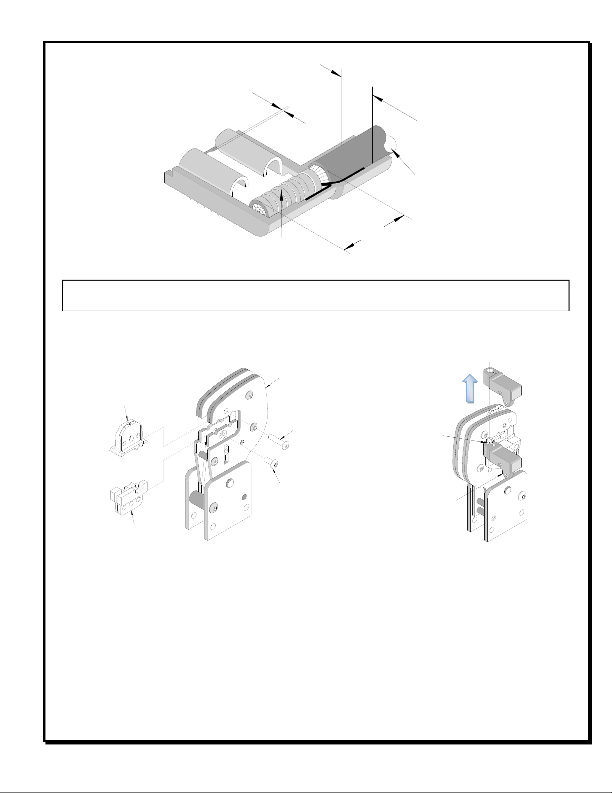
6. If the insulation part of the crimp needs to be adjusted, first loosen
the M4 screw on the upper tool jaw. Then insert a 2.5mm hex
wrench (supplied) into the set screw at the top of the upper die.
See Figure 7. A clockwise (CW) rotation decreases insulation
crimp while a counter-clockwise (CCW) rotation increases
insulation crimp. After adjusting, retighten the M4 screw.
Note: The tamper proof ratchet action will not release the tool until it
has been fully closed.
For the Battery Power Tool:
1. Cycle the Battery Power Tool to crimp the terminal to the wire.
2. Remove the crimped terminal from the terminal locator by pressing down on the wire stop and gently pulling on
the wire. The terminal locator can be in
either position.
3. Visually inspect the crimped terminal for
proper crimp location.
Maintenance
It is recommended that each operator of the
tool be made aware of, and responsible for,
the following maintenance steps:
1. Remove dust, moisture and other
contaminants with a clean brush, or soft,
lint-free cloth.
2. Do not use any abrasive materials that
could damage the tool.
3. Make certain all pins; pivot points and bearing surfaces in the tool head are protected with a thin coat of high
quality machine oil. Do not oil excessively. This tool was engineered for durability, but like any fine piece of
equipment, it needs cleaning and lubrication for a maximum service life of trouble-free crimping. The use of a
light oil, such as 30 weight automotive oil, every 5,000 crimps or monthly, will significantly enhance the tool life
and ensure a stable calibration. See Figure 8A or 8B for lubrication points.
4. Store the tool in a clean and dry area when not in use.
Miscrimps or Jams for Hand Crimp Tools Only (See Figure 12)
Should this tool ever become stuck or jammed in a partially closed position, Do Not force the handles open or
closed. The tool will open easily by rotating the small slotted screw marked with an arrow. See Figure 12.
WIRE
LUBRICATION
POINTS
(BOTH SIDES)
LIGHT OIL
(EVERY MONTH
OR
5,000 CRIMPS)
Figure 8A
Figure 8B
Figure 7
2.5mm HEX
WRENCH
LOOSEN
M4 SCREW
SET SCREW

Tool Kit for AviKrimpFully Insulated and-Insulated Quick Disconnect Flags
Doc No: ATS-6400188HM Release Date: 04-08-15 UNCONTROLLED COPY Page 5 of 9
Revision: B Revision Date: 06-17-15
Tool Calibration
A Certificate of Calibration (see last page) was supplied with the tool. To
recalibrate this tool, pin gauge measurements should be taken in each
conductor nest and compared to this chart. The tool should be
lubricated prior to recalibration to ensure consistent measurements.
Handle preload is factory set to 25-45 LBS. See How to Adjust Tool
Preload, see Figure 5 to recalibrate.
Nest Color Code
Wire Range
“X” Dimension Conductor Crimp
Crimp Inspection
Marking
Mean
Go
No Go
AWG
mm²
In.
mm
In.
mm
In.
mm
Yellow
10 - 12
5.00-3.30
.115
2.92
.112
2.84
.118
3.00
o
Warranty
This tool kit is for electrical terminal crimping purposes only. This tool kit is made of the best quality materials. All
vital components are long life tested. All tools are warranted to be free of manufacturing defects for a period of 30
days. Should such a defect occur, we will repair or exchange the tool kit free of charge. This repair or exchange
will not be applicable to altered, misused, or damaged tools.
CAUTION: Molex crimp specifications are valid only when used with Molex terminals and tooling.
CAUTIONS
1. Manually powered hand tools are intended for low volume or field repair. This tool is NOT intended for
production use. Repetitive use of this tool should be avoided.
2. Insulated rubber handles are not protection against electrical shock.
3. Wear eye protection at all times.
4. Use only the Molex terminals specified for crimping with this tool.
CAUTION: Repetitive use of this tool should be avoided.
Certification
Molex does not certify or re-certify commercial grade hand tools but rather supplies the following guidelines for
customers to re-certify hand tools.
This tool is qualified to pull force only. To re-certify, crimp a terminal to a wire, which has been stripped
12.7mm (1/2”) long, so there is no crimping of the insulation. Pull the terminal and wire at a rate no faster than
25mm (1.00”) per minute. See the Molex web site for the Quality Crimp Handbook for more information on pull
testing.
When the hand tool is no longer capable of achieving minimum pull force, it should be taken out of service and
replaced.
This tool is very difficult to disassemble and reassemble. Customer repair is not recommended.
PIN GAUGE IN
CONDUCTOR CRIMP
“ Confining ” Crimp
X

Tool Kit for AviKrimpFully Insulated and-Insulated Quick Disconnect Flags
Doc No: ATS-6400188HM Release Date: 04-08-15 UNCONTROLLED COPY Page 6 of 9
Revision: B Revision Date: 06-17-15
The chart below shows all applications for this Tool Kit.
Tool Kit
Order No.
Tool
Order no.
Tool
Description
Power Head
Order No.
Adapter
Description
Figure
No.
64001-8870
63810-1050
Hand Crimp Frame (Short)
N/A
N/A
10
63810-1000
Hand Crimp Frame (Long)
N/A
N/A
10
63816-0200
Battery Power Tool (110 V)
63816-0300
Power Crimp Head
11
63816-0250
Battery Power Tool (220 V)
63816-0300
Power Crimp Head
11
Applications for the Tool Kit
Hand Crimp Tool
Battery Powered Tool
Figure 10
Figure 11
WARNING: NEVER operate service, install tool kits, or adjust the Power Crimp Head without proper
instruction and without first reading and understanding the instructions in the proper Manual or
Specification Sheet. See Chart above for the correct Manual or Specification Sheet.
WARNING: NEVER install tooling or service this tool while it is into any power source. Make sure the
power is turned off.
CAUTION: Keep fingers away from the crimping area when operating this tool. It may cause severe injury.
CAUTION: Wear safety glasses when operating or serving this tool.
POWER
CRIMP
HEAD
LOCKING PINS
BATTERY
POWERED
TOOL
TOOLING KIT
HAND CRIMP
FRAME LONG
AND SHORT
TOOLING KIT

Tool Kit for AviKrimpFully Insulated and-Insulated Quick Disconnect Flags
Doc No: ATS-6400188HM Release Date: 04-08-15 UNCONTROLLED COPY Page 7 of 9
Revision: B Revision Date: 06-17-15
RATCHET
RELEASE SCREW
Figure 12
M4 X 8mm
LONG BHCS
2
1
3
M4 X 18mm
LONG BHCS
M4 X 10mm
LONG BHCS
2
4
WITH TOOL KIT
LOCATOR ONLY
HAND TOOL PARTS LIST
Item Number
Order Number
Description
Quantity
1
63810-1000
Hand Crimp Frame (Long)
1
2
64001-8870
Tool Kit with Locator
1
3
63811-4773
Locator Base
1
4
64001-8875
Locator
REF

Tool Kit for AviKrimpFully Insulated and-Insulated Quick Disconnect Flags
Doc No: ATS-6400188HM Release Date: 04-08-15 UNCONTROLLED COPY Page 8 of 9
Revision: B Revision Date: 06-17-15
Figure 11
1
2
2
M4 by 8 Long
BHCS
M4 by 18 Long
BHCS
M4 by 10 Long
BHCS
1
POWER HEAD PARTS LIST
Item
Order No
Engineering No.
Description
Quantity
1
63816-0300
63816-0300
Power Crimp Head
1
2
64001-8870
64003-1570
Tool Kit
1

Tool Kit for AviKrimpFully Insulated and-Insulated Quick Disconnect Flags
Doc No: ATS-6400188HM Release Date: 04-08-15 UNCONTROLLED COPY Page 9 of 9
Revision: B Revision Date: 06-17-15
Hand Crimp Tool
AviKrimp
Certificate of Calibration
Order No. 64001-8800
Tool Order Number __________________
Tool Revision ___________________
Serial Number ___________________
Date of Manufacture__________________
Handle Load Range at 1 inch from the Tips =______________
Actual =_____________
Pin Gauge of Conductor Nest/Nests or Slug height if the nest is the “F” Crimp style.
Range, Conductor Nest = ____________-- Actual = ______________
Technician ______________
Date of Calibration ______________
Calibration should be done every 5,000 cycles or 3 months.
Tools should be lubricated during this operation.
Visit our Web site at http://www.molex.com
This manual suits for next models
1
Table of contents
Other molex Crimping Tools manuals

molex
molex CR60622B User manual

molex
molex 207129 Series User manual

molex
molex 63811-9370 User manual

molex
molex TPX50-50 User guide

molex
molex CR5905 User manual

molex
molex 207129 Series User manual

molex
molex MTA-100 Manual

molex
molex 98897 User manual

molex
molex 63819-2800 User manual

molex
molex 50098 Series User manual

molex
molex 63825-7570 User manual

molex
molex 63825-8000 User manual

molex
molex RHT 2761-CC User manual

molex
molex HCS-125 Series User manual

molex
molex 63823-0400 User guide

molex
molex 207129 Series User manual

molex
molex 207129 Series User manual

molex
molex 63823-6900 User manual

molex
molex 207129 Series User manual

molex
molex 63823-6470 User manual