Monacor Carpower POWER-1/1000D User manual

POWER-1/1000D
Best.-Nr. 14.2650
Car-HiFi-Subwoofer-Endstufe
Car HiFi Subwoofer Power Amplifier
Amplificateur Subwoofer Hi-Fi Embarquée
Finale Di Potenza HiFi Per Subwoofer
Per Auto
Montageanleitung • Mounting instructions
Notice d’utilisation • Istruzioni per il montaggio
Montage-instructie • Manual de instrucciones
Instrukcja montazowa • Sikkerhedsoplysninger
Säkerhetsföreskrifter • Turvallisuudesta
•

2
www.carpower.com
Vor der Montage ...
Wir wünschen Ihnen viel Spaß mit dem neuen Gerät von
CARPOWER. Bitte lesen Sie diese Montageanleitung
vor dem Betrieb gründlich durch. Die Anleitung soll Ihnen
eine schnelle und einfache Montage ermöglichen. Sie
finden dazu hier alle nötigen Informationen. Durch die
Beachtung der Anleitung werden außerdem eventuelle
Schäden am Gerät durch unsachgemäße Montage ver-
mieden. Heben Sie die Anleitung für ein späteres Nach-
lesen auf.
Der deutsche Text beginnt auf der Seite 4.
Prior to Mounting ...
We wish you much pleasure with the new unit by CAR-
POWER. Please read these operating instructions care-
fully prior to operating the unit. With these operating in-
structions a quick and easy mounting will be possible.
You will find all necessary information here. By following
these instructions possible damage to the unit due to
improper mounting will be prevented. Please keep the
operating instructions for later use.
The English text starts on page 4.
D
A
CH
GB
Avant toute installation ...
Nous vous souhaitons beaucoup de plaisir à utiliser cet
appareil CARPOWER. Lisez ce mode d'emploi entière-
ment avant toute utilisation. Cette notice a pour objectif
de faciliter le montage. Vous y trouverez toutes les infor-
mations nécessaires. En outre, en respectant les
conseils donnés, vous éviterez tout mauvais montage et
donc dʼendommager lʼappareil. Conservez la notice pour
pouvoir vous y reporter ultérieurement.
La version française se trouve page 8.
Prima del montaggio ...
Vi auguriamo buon divertimento con il vostro nuovo
apparecchio CARPOWER. Leggete attentamente le
istruzioni prima di mettere in funzione l'apparecchio. Le
istruzioni che contengono tutte le informazioni necessa-
rie Vi permettono un montaggio rapido e semplice. Ri-
spettando quanto spiegato nelle istruzioni evitate even-
tuali danni allʼapparecchio in seguito ad un montaggio
non a regola dʼarte. Conservate le istruzioni per poterle
consultare anche in futuro.
Il testo italiano inizia a pagina 8.
F
B
CH
I
Przed uruchomieniem ...
Życzymy Państwu zadowolenia z nowego produktu
CARPOWER. Dzięki tej instrukcji montażu, będą pań-
stwo w stanie poznać wszystkie funkcje tego urządzenia.
Dzięki tej instrukcji obsługi będą Państwo w stanie
poznać wszystkie funkcje urządzenia. Stosując się do
instrukcji unikną państwo błędów i ewentualnego uszko-
dzenia urządzenia na skutek nieprawidłowego użytko-
wania. Prosimy zachować instrukcję.
Tekst polski zaczyna się na stronie 16.
Antes del montaje …
Tenemos de agradercerle el haber acquirido un equipo
CARPOWER y le deseamos un agradable a montar este
equipo fácilmente. Por favor, lea esta manual de instruc-
ciones atentamente antes de hacer funcionar el aparato.
Todos los informaciones necesarios están incluidos.
Para observar las instrucciones daños por un montaje
inadecuado están evitados. Por favor, guarde las ins-
trucciones para una futura utilización.
El texto en español empieza en la página 12.
PL
E
Voor u inschakelt ...
Wij wensen u veel plezier met uw nieuw toestel van
CARPOWER. Lees de handelingen, alvorens het toestel
in gebruik te nemen. Deze handleiding zal u in staat stel-
len alle mogelijkheden van dit toestel te doorgronden.
Door de instructies nauwgezet op te volgen, vermijdt u
bovendien dat het toestel slecht functioneert of dat u
door ondeskundige handelingen uzelf of het toestel
schade toebrengt. Bewaar de handleiding voor latere
raadpleging.
De Nederlandstalige tekst vindt u op pagina 12.
Inden De tænder for apparatet ...
Vi ønsker Dem god fornøjelse med Deres nye CAR-
POWER apparat. Læs oplysningerne for en sikker brug
af apparatet før ibrugtagning. Følg sikkerhedsoplysnin-
gerne for at undgå forkert betjening og for at beskytte
Dem og Deres apparat mod skade på grund af forkert
brug. Gem venligst denne betjeningsvejledning til senere
brug.
Du finder sikkerhedsanvisningen på side 20.
DK
Förskrift
Vi önskar dig mycket nöje med din nya enhet från CAR-
POWER. Läs gärna säkerhetsinstruktionerna innan du
använder enheten. Genom att följa säkerhetsinstruktio-
nerna kan många problem undvikas, vilket annars kan
skada enheten. Spara instruktionerna för framtida
användning.
Du finner säkerhetsinstruktionerna på sidan 20.
SEnnen virran kytkemistä …
Toivomme, että uusi CARPOWER -laitteesi tuo sinulle
paljon iloa ja hyötyä. Ole hyvä ja lue käyttöohjeet ennen
laitteen käyttöönottoa. Luettuasi käyttöohjeet voit käyt-
tää laitetta turvallisesti ja vältyt laitteen väärinkäytöltä.
Ole hyvä ja säilytä käyttöohjeet myöhempää tarvetta var-
ten.
Turvallisuusohjeet löytyvät sivulta 21.
FIN
NL
B

FUSE
1
2
SPEAKER
POWER IN
+12V GNDREM
R
L
R
L
LINE IN LINE OUT
PROT
POWER
LP
35 250
Hz
SUBSONIC
15 55
Hz
BASS EQ
015
dB
REMOTEPHASE
0∞180 ∞
GAIN
60.2
V
BAL. IN
POWER-1/1000D CLASS D MONO AMPLIFIER
Radio
Subwoofer
min. 1Ω
Battery
Fuse
150A
Chassis
RL On = 12V
Speaker L
Speaker R
Chassis
RL
Main amplifier
-
+
+
–
+
–
max.
20cm
Remote Control
Power capacitor
optional
12345678
TP
Bass
Tre
EJECT CD / RADIO
AM
FM
CD Menu
oder • or
2 x Subwoofer
min. 2Ω
-
+
-
+
Chassis
PROT PWR
LEVEL
SPEAKER
PROT PWR
LEVEL
R
L
R
L
LINE IN LINE OUT
PROT
POWER
LP
35 250
Hz
SUBSONIC
15 55
Hz
BASS EQ
015
dB
REMOTEPHASE
0∞180 ∞
GAIN
6 0.2
V
BAL. IN
POWER-1/1000D CLASS D MONO AMPLIFIER
3
1234567891011 12
13 14 15 16 17
D Verdrahtung
GB Wiring
F Câblage
I Cablaggio
NL Bedrading
E Conexiones
PL Podłączanie
FUSE
1
2
SPEAKER
POWER IN
+12V GNDREM

Bitte klappen Sie die Seite 3 heraus. Sie sehen
dann immer die beschriebenen Bedienelemente
und Anschlüsse.
Inhalt
1 Übersicht der Bedienelemente und
Anschlüsse . . . . . . . . . . . . . . . . . . . . . . . . . 4
1.1 Frontseite . . . . . . . . . . . . . . . . . . . . . . . . . . . 4
1.2 Rückseite . . . . . . . . . . . . . . . . . . . . . . . . . . . 4
2 Sicherheitshinweise . . . . . . . . . . . . . . . . . . 4
3 Vorsicht bei hohen Lautstärken . . . . . . . . 5
4 Einsatzmöglichkeiten . . . . . . . . . . . . . . . . . 5
5 Montage . . . . . . . . . . . . . . . . . . . . . . . . . . . . 5
6 Endstufe anschließen . . . . . . . . . . . . . . . . 5
6.1 Stromversorgung . . . . . . . . . . . . . . . . . . . . . 5
6.1.1 Betriebsspannung . . . . . . . . . . . . . . . . . . . 5
6.1.2 Masseanschluss . . . . . . . . . . . . . . . . . . . . 5
6.1.3 Steuerspannung zum Einschalten . . . . . . . 5
6.2 Line-Ein- und Ausgänge . . . . . . . . . . . . . . . . 6
6.3 Lautsprecher . . . . . . . . . . . . . . . . . . . . . . . . . 6
6.4 Fernbedienung . . . . . . . . . . . . . . . . . . . . . . . 6
7 Inbetriebnahme . . . . . . . . . . . . . . . . . . . . . . 6
8 Fehlerbeseitigung . . . . . . . . . . . . . . . . . . . . 7
9 Technische Daten . . . . . . . . . . . . . . . . . . . . 7
1 Übersicht der Bedienelemente
und Anschlüsse
1.1 Frontseite
1Cinch-Buchsen LINE IN für das Eingangssignal
2symmetrischer Eingang über eine Hosiden-
Buchse, alternativ zum Eingang LINE IN (1)
3Trimmregler GAIN zur Eingangspegelanpassung
4Trimmregler PHASE zum Einstellen der Phasen-
lage 0 – 180° (siehe Kap. 7)
5Anschluss REMOTE für die Fernbedienung (12)
6Trimmregler BASS EQ zur Bassanhebung bis
15 dB bei 50 Hz
7Trimmregler SUBSONIC zum Einstellen der
Trennfrequenz des Subsonic-Filters, das den
Infraschall unterdrückt
8Trimmregler LP zum Einstellen der Trennfrequenz
des Tiefpasses (die Frequenz, die vom Sub-
woofer nicht mehr wiedergegeben werden soll)
9Anzeige PROT leuchtet bei aktivierter Schutz-
schaltung:
1. wenn am Lautsprecherausgang (17) ein Kurz-
schluss aufgetreten ist
2. wenn die Endstufe überhitzt ist
10 Betriebsanzeige POWER
11 Cinch-Buchsen LINE OUT zum Anschluss einer
weiteren Car-HiFi-Endstufe
Hier liegt das durchgeschleifte Eingangssignal
der Buchsen LINE IN (1) oder BAL. IN (2) an.
12 Fernbedienung für die Pegeleinstellung
1.2 Rückseite
13 Sicherungen: 2 × 70 A
Eine durchgebrannte Sicherung nur durch eine
gleichen Typs ersetzen!
14 Anschluss für die Versorgungsspannung +12 V
15 Steuereingang REM zum Einschalten der End-
stufe über eine 12-V-Spannung
16 Masseanschluss GND
17 Lautsprecheranschlüsse SPEAKER
2 Sicherheitshinweise
Die Endstufe entspricht der Kfz-Richtlinie.
GVerwenden Sie für die Reinigung nur ein trocke-
nes, weiches Tuch, auf keinen Fall Chemikalien
oder Wasser.
GWird das Gerät zweckentfremdet, nicht richtig an-
geschlossen, falsch bedient oder nicht fachgerecht
repariert, kann keine Haftung für daraus resultie-
rende Sach- oder Personenschäden und keine
Garantie für das Gerät übernommen werden.
WARNUNG Beim Anschluss der Car-HiFi-End-
stufe an die Autobatterie ist beson-
dere Sorgfalt geboten. Bei Kurz-
schlüssen können sehr gefährlich
hohe Ströme fließen. Schrauben Sie
deshalb unbedingt vor dem Anschluss
die Minusklemme der Autobatterie ab.
Die Endstufe muss fest und fachgerecht an einer
mechanisch stabilen Stelle im Auto montiert wer-
den, damit sie sich nicht löst und zu einem gefähr-
lichen Geschoss wird.
Während des Betriebs kann das Gerät sehr heiß
werden. Platzieren Sie darum keine hitzeempfind-
lichen Gegenstände in der Nähe und berühren Sie
die Endstufe nicht während des Betriebs.
Please unfold page 3. Then you can always see the
operating elements and connections described.
Contents
1 Operating Elements and Connections . . . 4
1.1 Front panel . . . . . . . . . . . . . . . . . . . . . . . . . . 4
1.2 Rear panel . . . . . . . . . . . . . . . . . . . . . . . . . . 4
2 Safety Notes . . . . . . . . . . . . . . . . . . . . . . . . 4
3 Caution in Case of High Volumes . . . . . . . 5
4 Applications . . . . . . . . . . . . . . . . . . . . . . . . 5
5 Mounting . . . . . . . . . . . . . . . . . . . . . . . . . . . 5
6 Connecting the Power Amplifier . . . . . . . . 5
6.1 Power supply . . . . . . . . . . . . . . . . . . . . . . . . 5
6.1.1 Operating voltage . . . . . . . . . . . . . . . . . . . . 5
6.1.2 Ground connection . . . . . . . . . . . . . . . . . . . 5
6.1.3 Control voltage for switching-on . . . . . . . . . 5
6.2 Line inputs and line outputs . . . . . . . . . . . . . 6
6.3 Speakers . . . . . . . . . . . . . . . . . . . . . . . . . . . 6
6.4 Remote control . . . . . . . . . . . . . . . . . . . . . . . 6
7 Setting into Operation . . . . . . . . . . . . . . . . 6
8 Trouble Shooting . . . . . . . . . . . . . . . . . . . . 7
9 Specifications . . . . . . . . . . . . . . . . . . . . . . . 7
1 Operating Elements and Connections
1.1 Front panel
1Jacks phono LINE IN for the input signal
2Balanced input via a Hosiden jack, as an alterna-
tive to the input LINE IN (1)
3Trimming control GAIN for input level matching
4Trimming control PHASE for adjusting the phase
0 – 180° (see chapter 7)
5Connection REMOTE for the remote control (12)
6Trimming control BASS EQ for bass boosting up
to 15 dB at 50 Hz
7Trimming control SUBSONIC for adjusting the
crossover frequency of the subsonic filter which
suppresses the infrasound
8Trimming control LP for adjusting the crossover
frequency of the low pass (the frequency not to
be reproduced any more by the subwoofer)
9LED PROT lights up with activated protective cir-
cuit:
1. if a short circuit has occurred at the speaker
output (17)
2. if the power amplifier is overheated
10 LED POWER
11 Phono jacks LINE OUT for connection of another
car HiFi power amplifier
Here the fed-through input signal of jacks LINE
IN (1) or BAL. IN (2) is present.
12 Remote control for the level adjustment
1.2 Rear side
13 Fuses: 2 × 70 A
Only replace a blown fuse by one of the same
type!
14 Connection for the supply voltage +12 V
15 Control input REM for switching on the power
amplifier via a 12 V voltage
16 Ground connection GND
17 SPEAKER connections
2 Safety Notes
The power amplifier corresponds to the directive for
automobiles.
GFor cleaning only use a dry, soft cloth, by no
means chemicals or water.
GNo guarantee claims for the unit and no liability for
any resulting personal damage or material dam-
age will be accepted if the unit is used for other
purposes than originally intended, if it is not cor-
rectly connected or operated, or not repaired in an
expert way.
WARNING When connecting the car HiFi power
amplifier to the car battery, be espe-
cially careful. In case of short circuits
there may be dangerously high cur-
rents. Therefore, prior to the connec-
tion, it is indispensable to screw off the
negative terminal of the car battery.
The power amplifier must be mounted to a
mechanically stable place in the car. It must be skil-
fully fixed so that it does not get loose and turn into
a dangerous projectile.
During operation the unit may become very hot.
Therefore, do not place any objects sensitive to
heat close to it and do not touch the power ampli-
fier while in operation.
4
GB
D
A
CH

3 Vorsicht bei hohen Lautstärken
GBei ausgeschaltetem Motor sollte die Car-HiFi-
Anlage nicht längere Zeit mit hoher Lautstärke
betrieben werden. Die Autobatterie wird schnell
entladen und liefert dann eventuell nicht mehr ge-
nügend Energie zum Starten.
4 Einsatzmöglichkeiten
Die Endstufe POWER-1/1000D ist speziell für den
Betrieb eines hochbelastbaren Subwoofers in einer
Car-HiFi-Anlage konzipiert. Die Ausgangsstufe
arbeitet digital (D-Betrieb), wodurch ein hoher Wir-
kungsgrad bei minimaler Erwärmung erreicht wird.
Die Sinusausgangsleistung beträgt max. 1200 W bei
Verwendung eines 1-Ω-Subwoofers.
Die Endstufe ist mit einem einstellbaren Tief-
passfilter ausgestattet, sodass keine weiteren Filter
für den Betrieb benötigt werden. Zum Schutz des
Subwoofers vor Frequenzen unterhalb des mensch-
lichen Hörbereiches (Infraschall) ist ein einstellbares
Subsonic-Filter integriert.
5 Montage
Bei der Auswahl des Montageplatzes unbedingt die
folgenden Punkte beachten:
GDas 12-V-Stromversorgungskabel von der Batte-
rie zur Car-HiFi-Endstufe sollte so kurz wie mög-
lich sein. Es ist günstiger, längere Lautsprecher-
kabel zu verwenden und dafür ein kürzeres
Stromversorgungskabel.
GDie Masseleitung von der Endstufe zum Fahr-
zeugchassis sollte ebenfalls so kurz wie möglich
sein.
GUm die entstehende Wärme der Car-HiFi-
Endstufe ableiten zu können, muss eine ausrei-
chende Belüftung gewährleistet sein.
GWegen der beim Bremsen auftretenden Kräfte
muss die Endstufe an einer mechanisch stabilen
Stelle fest angeschraubt werden.
GDie Sicherungen und die Regler müssen zugän-
gig sein.
GDie Endstufe sollte elektrisch isoliert vom Fahr-
zeugchassis montiert werden.
Die Endstufe über die vier Befestigungspunkte am
Kühlkörper an geeigneter Stelle festschrauben.
6 Endstufe anschließen
GDer Anschluss der Car-HiFi-Endstufe an das Bord-
netz darf nur durch qualifiziertes Fachpersonal
erfolgen.
GUnbedingt vor dem Anschluss die Minusklemme
der Autobatterie abschrauben, um bei einem
eventuellen Kurzschluss während der Installation
Schäden zu vermeiden.
GDie erforderlichen Kabel so verlegen, dass deren
Isolierung nicht beschädigt werden kann.
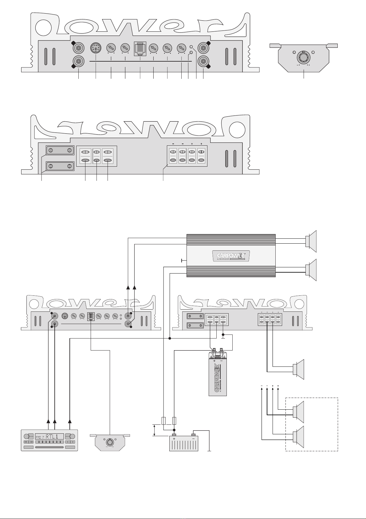
Der gesamte Anschluss ist in der Abbildung 3 auf
der Seite 3 dargestellt.
6.1 Stromversorgung
6.1.1 Betriebsspannung
Den Anschluss „+12V“ (14) über ein entsprechendes
Kabel mit der Plusklemme der Autobatterie verbin-
den. Um den Spannungsverlust durch das Kabel
gering zu halten, sollte mindestens ein Querschnitt
von 30 mm2verwendet werden, z. B. CPC-300/RT*.
Um die neu verlegte 12-V-Leitung gegen einen Kurz-
schluss abzusichern, muss eine 150-A-Vorsicherung
in unmittelbarer Nähe der Batterie zwischengesetzt
werden (max. Kabellänge zur Batterie 20 cm).
Zur Stabilisierung der Betriebsspannung für die
Endstufe und der damit verbundenen Leistungsstei-
gerung sowie Klangverbesserung wird ein Power-
Kondensator empfohlen (z. B. CAP-…*).
6.1.2 Masseanschluss
Den Masseanschluss GND (16) über ein Kabel mit
einem Querschnitt von mindestens 30 mm2(z. B.
CPC-300/SW*) mit der Masse des Autos oder bes-
ser direkt mit der Minusklemme der Autobatterie ver-
binden.
Hinweise:
1. Bei Verwendung der Karosserie als Massean-
schluss muss die verwendete Stelle einen guten
elektrischen Kontakt zur Hauptkarosserie aufwei-
sen (z. B. durch ausreichend viele Schweiß-
punkte). Eventueller Lack am Kontaktpunkt muss
vollständig entfernt werden.
2. Zur Vermeidung von Masseschleifen muss die
Masse des Autoradios an die Stelle gelegt wer-
den, an der auch die Endstufe an Masse liegt.
6.1.3 Steuerspannung zum Einschalten
Die Car-HiFi-Endstufe wird durch eine Steuerspan-
nung von +12 V am Anschluss REM (15) ein- und
ausgeschaltet. Den Anschluss REM mit dem 12-V-
Schaltausgang vom Autoradio verbinden (Anschluss
für eine Motorantenne, eventuell mit der Motoran-
tenne parallel schalten).
VORSICHT Stellen Sie die Lautstärke nie sehr
hoch ein. Extrem hohe Lautstärken
können das Gehör schädigen.
Das Ohr gewöhnt sich an hohe Laut-
stärken und empfindet sie nach eini-
ger Zeit als nicht mehr so hoch. Erhö-
hen Sie darum eine einmal einge-
stellte hohe Lautstärke nach der
Gewöhnung nicht weiter.
Während des Autofahrens dürfen Signaltöne, z. B.
von einem Rettungswagen, nicht durch eine zu hohe
Lautstärke der Car-HiFi-Anlage übertönt werden.
Soll das Gerät endgültig aus dem Betrieb
genommen werden, übergeben Sie es zur
umweltgerechten Entsorgung einem örtli-
chen Recyclingbetrieb.
3 Caution in Case of High Volumes
GWith the motor switched off, the car HiFi system
should not be in operation at high volume for a
longer period of time. The car battery will quickly
be discharged, and then it may not be capable any
more of supplying sufficient energy for starting the
car.
4 Applications
The power amplifier POWER-1/1000D has especial-
ly been designed for the operation of a subwoofer of
high power capability in a car HiFi system. Due to
the digital operation (D mode) of the output amplifier,
a high efficiency at minimum heating-up is reached.
The rms output power is 1200 W as a maximum
when using a 1 Ω subwoofer.
The power amplifier is equipped with an adjust-
able low pass filter so that no further filters are re-
quired for the operation. As a protection of the sub-
woofer against frequencies below the human hear-
ing range (infrasound) an adjustable subsonic filter
is integrated.
5 Mounting
When choosing the place of mounting, always
observe the following items in any case:
GThe 12 V power supply cable from the battery to
the car HiFi power amplifier should be as short as
possible. It is better to use longer speaker cables
and a shorter power supply cable instead.
GThe ground cable from the power amplifier to the
chassis of the car should also be as short as pos-
sible.
GFor carrying off the heat being generated by the
car HiFi power amplifier, a sufficient ventilation
has to be ensured.
GAs forces occur during braking, the power ampli-
fier must tightly be screwed to a mechanically
stable place.
GThe fuses and the controls must be accessible.
GThe power amplifier should be mounted electri-
cally insulated from the car chassis.
Tightly screw the amplifier via the four fixing points
at the heat sink at a suitable place.
6 Connection of the Power Amplifier
GThe connection of the car HiFi power amplifier to
the electric system of the car must only be carried
out by qualified, specialized personnel.
GTo prevent damage in case of a possible short cir-
cuit during installation, prior to the connection it is
indispensable to screw off the negative terminal of
the car battery.
GLay the necessary cables so that their insulation
cannot be damaged.
The complete connection is shown in fig. 3 on page 3.
6.1 Power supply
6.1.1 Operating voltage
Connect the terminal “+12V” (14) via a correspond-
ing cable to the positive terminal of the car battery.
To keep the voltage loss by the cable as low as pos-
sible, a minimum cross section of 30 mm2should be
used, e. g. CPC-300/RT*. To protect the newly laid
12 V cable against a short circuit, insert an additional
150 A fuse very close to the battery (max. cable
length to the battery 20 cm).
To stabilize the operating voltage for the power
amplifier and thus the resulting power increase and
sound improvement, a power capacitor is recom-
mended (e. g. CAP-...*).
6.1.2 Ground connection
Connect the ground terminal GND (16) via a cable
with a minimum cross section of 30 mm2(e. g. CPC-
300/SW*) to the ground of the car or better directly
to the negative terminal of the car battery.
Notes:
1. When using the chassis as a ground connection,
the place used must have a good electrical con-
tact to the main chassis (e. g. by a sufficient num-
ber of welding points). Any lacquer at the point of
contact must completely be removed.
2. To prevent ground loops, the ground of the car
radio must be applied at the place where also the
power amplifier is grounded.
6.1.3 Control voltage for switching-on
The car HiFi power amplifier is switched on and off
by a control voltage of +12 V at the terminal REM
(15). Connect the terminal REM to the 12 V control
output of the car radio (connection for a motor
antenna, if necessary, to be connected in parallel to
the motor antenna).
If the unit is to be put out of operation defi-
nitively, take it to a local recycling plant for
a disposal which is not harmful to the envi-
ronment.
CAUTION Never adjust the volume very high.
Extremely high volumes may damage
your hearing.
The human ear gets accustomed to
high volumes which do not seem to
be so high any more after some time.
Therefore, do not further increase a
high volume which has once been
adjusted after getting used to it.
While driving in the car, signal sounds, e. g. by an
ambulance, must not be drowned by the volume of
the car HiFi system which has been adjusted too
high.
5
GB
D
A
CH
* von CARPOWER
* by CARPOWER

6.2 Line-Ein- und Ausgänge
1) Die beiden Eingangsbuchsen LINE IN (1) über
Cinch-Kabel mit den Line-Ausgängen der Signal-
quelle (z. B. Autoradio) verbinden oder falls
vorhanden mit den Ausgängen für einen Sub-
woofer-Verstärker. Sind am Autoradio keine Line-
Ausgänge vorhanden, können die Lautsprecher-
ausgänge des Autoradios über einen entspre-
chenden Audio-Übertrager (z. B. FGA-22HQ von
CARPOWER) mit den Eingängen der Endstufe
verbunden werden.
Ist die Signalquelle mit einem symmetrischen
Line-Ausgang ausgestattet, kann alternativ die
Buchse BAL. IN (2) als Eingang genutzt werden.
Die Anschlussbelegung der Buchse ist in den
technischen Daten auf der Seite 7 angegeben.
2) Der Line-Eingang der Endstufe für die Hauptlaut-
sprecher kann über ein Cinch-Kabel an die Buch-
sen LINE OUT (11) angeschlossen werden. An
diesen Buchsen liegt das Eingangssignal der
Buchsen LINE IN (1) oder BAL. IN (2) an.
6.3 Lautsprecher
Den Subwoofer (Impedanz min. 1 Ω) oder eine Sub-
woofer-Gruppe mit einer Gesamtimpedanz von min-
destens 1 Ω an die Kontakte SPEAKER (17) an-
schließen. Die beiden Kontaktpaare „+“ und „
-
“ sind
parallel geschaltet, sodass bei Bedarf auch zwei
Subwoofer mit einer Impedanz von je 2 Ω ange-
schlossen werden können.
6.4 Fernbedienung
Mit der Fernbedienung (12) lässt sich die Lautstärke
der Bässe je nach Musikmaterial unterschiedlich
hoch einstellen. Außerdem sind auf ihr auch die
LEDs PWR (Betriebsanzeige) und PROT (Schutz-
schaltung aktiviert) vorhanden, die den LEDs
POWER (10) und PROT (9) an der Endstufe ent-
sprechen.
Die Fernbedienung in Fahrerreichweite montie-
ren und über das beiliegende Anschlusskabel mit
der Buchse REMOTE (5) der Endstufe verbinden.
7 Inbetriebnahme
1) Die Trennfrequenz (d. h. die Frequenz, die vom
Subwoofer nicht mehr wiedergegeben werden
soll) mit dem Regler LP (8) einstellen. Die Fein-
einstellung erfolgt nach der Pegeleinstellung mit
entsprechenden Messgeräten.
2) Mit dem Regler SUBSONIC (7) die untere Über-
tragungsfrequenz des Subwoofers einstellen.
Der Subwoofer wird so durch das Subsonic-Filter
vor sehr tiefen Frequenzen geschützt.
3) Den Regler GAIN (3) ganz nach links in die Posi-
tion „6 V“ drehen und wenn die Fernbedienung
(12) angeschlossen ist, deren Regler ganz nach
rechts in die Position „+“.
4) Die Car-HiFi-Anlage komplett einschalten. Die
Betriebsanzeige POWER (10) leuchtet, die End-
stufe ist aber noch ein paar Sekunden stumm
geschaltet (Einschaltverzögerung).
5) Die Signalquelle, z. B. das Autoradio, auf maxi-
male, nicht verzerrende Lautstärke einstellen.
Tipp Um Störeinstrahlungen durch die Autoelek-
trik so gering wie möglich zu halten, sollte
der Ausgangspegel der Signalquelle min.
1,5 V betragen.
6) Mit dem Regler GAIN (3) die Lautstärke des Sub-
woofers an die der Hauptlautsprecher anpassen.
Den Regler maximal so weit aufdrehen, dass
keine Verzerrungen auftreten.
7) Bei Bedarf lassen sich die Bässe mit dem Regler
BASS EQ (6) anheben (max. 15 dB/50 Hz).
8) Mit dem Regler PHASE (4) die Phasenlage zu
den Hauptlautsprechern einstellen. Besonders
bei zusätzlich installierten Kickbasslautsprechern
wirkt sich eine falsche Phasenlage negativ im
Klangbild aus (zu geringer Bass). Den Regler
PHASE auf optimale Basswiedergabe einstellen.
!
Vor dem ersten Einschalten sollte die kom-
plette Verdrahtung der Car-HiFi-Endstufe
noch einmal auf Richtigkeit überprüft werden.
Erst danach die Minusklemme der Autobat-
terie wieder anschließen.
Wichtig! Bei der Auswahl geeigneter Lautsprecher
unbedingt deren mechanische und elektrische
Belastbarkeit im Zusammenhang mit der genutz-
ten Endstufenleistung berücksichtigen (siehe auch
technische Daten der Endstufe Seite 7).
6.2 Line inputs and Line outputs
1) Connect the two input jacks LINE IN (1) via
cables with phono connectors to the line outputs
of the signal source (e. g. car radio) or, if pro-
vided, to the outputs for a subwoofer amplifier. If
the car radio is not equipped with line outputs, the
speaker outputs of the car radio may be con-
nected via a corresponding audio transformer
(e. g. FGA-22HQ from CARPOWER) to the
inputs of the power amplifier.
If the signal source is equipped with a bal-
anced line output, the jack BAL. IN (2) can alter-
natively be used as an input. The pin configura-
tion of the jack is indicated in the specifications
on page 7.
2) The line input of the power amplifier for the main
speakers may be connected via a cable with
phono connectors to the jacks LINE OUT (11).
The input signal of the jacks LINE IN (1) or
BAL. IN (2) is present at these jacks.
6.3 Speakers
Connect the subwoofer (minimum impedance 1 Ω)
or a subwoofer group with a total impedance of 1 Ω
as a minimum to the contacts SPEAKER (17). The
two pairs of contacts “+” and “
-
” are connected in
parallel so that also two subwoofers with an imped-
ance of 2 Ω each may be connected, if required.
6.4 Remote control
The remote control (12) allows to reduce the volume
of the bass frequencies to a different level, depend-
ing on the music material. Besides, it is provided
with the LEDs PWR (power indication) and PROT
(protective circuit activated) which correspond to the
LEDs POWER (10) and PROT (9) at the power
amplifier.
Mount the remote control within driverʼs reach
and connect it with the supplied cable to the jack
REMOTE (5) of the power amplifier.
7 Setting into Operation
1) Adjust the crossover frequency (i. e. the fre-
quency which is not to be reproduced by the sub-
woofer any more) with the control LP (8). The fine
adjustment is made with corresponding meters
after the level adjustment.
2) With the control SUBSONIC (7) adjust the lower
radiating frequency of the subwoofer. Thus, the
subwoofer is protected by the subsonic filter
against very low frequencies.
3) Turn the control GAIN (3) to the left stop to posi-
tion “6 V” and, if the remote control (12) has been
connected, turn its control to the right stop to
position “+”.
4) Switch on the car HiFi system completely. The
LED POWER (10) lights up, but the power ampli-
fier is still muted for a few seconds (switch-on
delay).
5) Adjust the signal source, e. g. the car radio, to
maximum, non-distorting volume.
Hint To keep the interference by the electric
system of the car as low as possible, the
output level of the signal source should be
1.5 V as a minimum.
6) With the control GAIN (3) match the volume of
the subwoofer to that of the main speakers. Turn
up the control so far as a maximum that no dis-
tortions occur.
7) With the control BASS EQ (6) the bass frequen-
cies can be boosted (max. 15 dB/50 Hz), if
required.
8) With the control PHASE (4) adjust the phase to
the main speakers. Especially if kick bass speak-
ers are additionally installed, an incorrect phase
shows a negative sound effect (bass frequencies
are too low). Adjust the control PHASE to opti-
mum bass reproduction.
!
Prior to the first switching-on, check the entire
wiring of the car HiFi power amplifier once
again for correctness before reconnecting the
negative terminal of the car battery.
Important! When choosing suitable speakers, pay
in any case attention to their mechanical and
electrical capability in connection with the power
used of the power amplifier (also see specifications
of the power amplifier on page 7).
6
GB
D
A
CH

8 Fehlerbeseitigung
Ist nach dem Einschalten der Car-HiFi-Anlage kein
Ton zu hören, den Fehler mithilfe der beiden LEDs
POWER (10) und PROT (9) näher lokalisieren.
Diese LEDs sind auch auf der Fernbedienung vor-
handen und mit PWR und PROT beschriftet.
LED POWER leuchtet nicht
1) Die Sicherungen (13) der Car-HiFi-Endstufe (2 ×
70 A) und die Vorsicherung (150 A) an der Auto-
batterie überprüfen. Defekte Sicherungen aus-
wechseln. Nur Sicherungen mit den angegebe-
nen Werten verwenden. Auf keinen Fall einen
höheren Wert einsetzen. Die Endstufe kann be-
schädigt werden und die Garantie erlischt.
2) Das 12-V-Stromversorgungskabel sowie das
Massekabel auf korrekten Anschluss und Unter-
brechung kontrollieren.
3) An der Klemme REM (15) der Endstufe messen,
ob +12 V anliegt. Wenn nicht, die Leitung an der
Klemme REM entfernen und vorübergehend die
Klemmen REM und „+12V“ (14) überbrücken.
Schaltet die Endstufe jetzt ein, liegt der Fehler in
der fehlenden Steuerspannung. Den 12-V-Schalt-
ausgang des Autoradios und das entsprechende
Anschlusskabel zur Endstufe überprüfen.
LED POWER leuchtet
1) Die Verbindungskabel von der Signalquelle zur
Car-HiFi-Endstufe überprüfen. Sind die Stecker
richtig eingesteckt? Sind die Leitungen unterbro-
chen?
2) Die Signalquelle überprüfen. Ist die Signalquelle
eingeschaltet? Sind die richtigen Ausgänge ver-
wendet worden? Ist die Signalquelle defekt?
3) Die Lautsprecherkabel auf Unterbrechung über-
prüfen.
4) Die angeschlossenen Lautsprecher überprüfen.
LED PROT leuchtet
Die Endstufe ist mit einer Schutzschaltung gegen
Kurzschluss am Lautsprecherausgang und gegen
Überhitzung gesichert. Ist die Schutzschaltung akti-
viert, leuchtet die Anzeige PROT (9) und der Laut-
sprecherausgang ist stummgeschaltet.
Bei einer Überhitzung schaltet die Endstufe
nach dem Abkühlen automatisch wieder ein. Bei
einem Kurzschluss am Lautsprecherausgang muss
nach der Fehlerbeseitigung zum Zurücksetzen der
Schutzschaltung die 12-V-Steuerspannung kurz ab-
geschaltet werden (z. B. Autoradio ausschalten).
8 Trouble Shooting
If there is no sound after switching on the car HiFi
system, locate the fault more precisely by means of
the two LEDs POWER (10) and PROT (9). These
LEDs are also available on the remote control and
lettered with PWR and PROT.
The LED POWER does not light up
1) Check the fuses (13) of the car HiFi amplifier (2 ×
70 A) and the additional fuse (150 A) at the car
battery. Replace defective fuses. Only use fuses
with the indicated values. Do not insert a higher
value in any case. The power amplifier may be
damaged and the guarantee expires.
2) Check the 12 V power supply cable and the
ground cable for correct connection and for inter-
ruption.
3) Check at the terminal REM (15) of the power
amplifier if +12 V is present. If not, remove the
cable at the terminal REM and temporarily short-
circuit the terminals REM and “+12V” (14). If the
power amplifier switches on now, the fault is due
to the missing control voltage. Check the 12 V
control output of the car radio and the corre-
sponding connection cable to the power amplifier.
The LED POWER lights up
1) Check the connection cables from the signal
source to the car HiFi power amplifier. Are the
plugs correctly connected? Are the cables inter-
rupted?
2) Check the signal source. Is the signal source
switched on? Have the correct outputs been
used? Is the signal source defective?
3) Check the speaker cables for interruption.
4) Check the connected speakers.
The LED PROT lights up
The power amplifier is protected with a protective
circuit against short circuit at the speaker output and
against overheating. If the protective circuit is acti-
vated, the LED PROT (9) lights up and the speaker
output is muted.
In case of overheating, the power amplifier auto-
matically switches on again after cooling-down. In
case of a short circuit at the speaker output, after
eliminating the error, the 12 V control voltage must
shortly be switched off (e. g. switch off the car radio)
to reset the protective circuit.
7
GB
D
A
CH
Diese Bedienungsanleitung ist urheberrechtlich für MONACOR
®
INTERNATIONAL GmbH & Co. KG
geschützt. Eine Reproduktion für eigene kommerzielle Zwecke – auch auszugsweise – ist untersagt.
All rights reserved by MONACOR
®
INTERNATIONAL GmbH & Co. KG. No part of this instruction manual
may be reproduced in any form or by any means for any commercial use.
9 Technische Daten
Ausgangsleistung
Maximale Leistung: . . . . . . 1500 WMAX
Sinusleistung an 1 Ω: . . . . . 1200 WRMS
Sinusleistung an 2 Ω: . . . . . 870 WRMS
Sinusleistung an 4 Ω: . . . . . 530 WRMS
Frequenzbereich: . . . . . . . . . 20 – 300 Hz
Min. Lautsprecherimpedanz: . 1 Ω
Eingänge
Anschlüsse: . . . . . . . . . . . . 2 × Cinch (asym.)
1 × Hosiden (sym.)
Empfindlichkeit: . . . . . . . . . 0,2–6V
Tiefpass: . . . . . . . . . . . . . . . . 35 – 250 Hz,
18 dB/Oktave
Subsonic-Filter: . . . . . . . . . . . 15 – 55 Hz,
12 dB/Oktave
Bassanhebung: . . . . . . . . . . . 0 – 15 dB bei 50 Hz
Störabstand: . . . . . . . . . . . . . > 80 dB (A bewertet)
Klirrfaktor: . . . . . . . . . . . . . . . < 0,4 %
Stromversorgung: . . . . . . . . . 10 – 16 V /140 A
Einsatztemperatur: . . . . . . . . 0 – 40 °C
Abmessungen: . . . . . . . . . . . 255 × 65 × 412 mm
Gewicht: . . . . . . . . . . . . . . . . 6,1 kg
Anschlussbelegung der Hosiden-Buchse
1, 2 Abschirmung
3 linker Kanal Signal
-
4 rechter Kanal Signal
-
5 linker Kanal Signal +
6 rechter Kanal Signal +
Änderungen vorbehalten.
BAL. IN
2
4
6
1
3
5
9 Specifications
Output power
Maximum power: . . . . . . . . 1500 WMAX
rms power at 1 Ω: . . . . . . . 1200 WRMS
rms power at 2 Ω: . . . . . . . 870 WRMS
rms power at 4 Ω: . . . . . . . 530 WRMS
Frequency range: . . . . . . . . . 20 – 300 Hz
Min. speaker impedance: . . . 1 Ω
Inputs
Connections: . . . . . . . . . . . 2 × RCA (unbal.)
1 × Hosiden (bal.)
Sensitivity: . . . . . . . . . . . . . 0.2–6V
Low pass: . . . . . . . . . . . . . . . 35 – 250 Hz,
18 dB/octave
Subsonic filter: . . . . . . . . . . . . 15 – 55 Hz,
12 dB/octave
Bass boosting: . . . . . . . . . . . . 0 – 15 dB at 50 Hz
S/N ratio: . . . . . . . . . . . . . . . > 80 dB (A weighted)
THD: . . . . . . . . . . . . . . . . . . . < 0.4 %
Power supply: . . . . . . . . . . . . 10 – 16 V /140 A
Ambient temperature: . . . . . . 0 – 40 °C
Dimensions: . . . . . . . . . . . . . 255 × 65 × 412 mm
Weight: . . . . . . . . . . . . . . . . . 6.1 kg
Pin configuration of the Hosiden jack
1, 2 screening
3 left channel signal
-
4 right channel signal
-
5 left channel signal +
6 right channel signal +
Subject to technical modification.
BAL. IN
2
4
6
1
3
5

Ouvrez le présent livret page 3 de manière à
visualiser les éléments et branchements.
Table des matières
1 Eléments et branchement . . . . . . . . . . . . . 8
1.1 Face avant . . . . . . . . . . . . . . . . . . . . . . . . . . 8
1.2 Face arrière . . . . . . . . . . . . . . . . . . . . . . . . . 8
2 Conseils dʼutilisation et de sécurité . . . . . 8
3 Mises en garde en cas de volume élevé . . 9
4 Possibilités dʼutilisation . . . . . . . . . . . . . . 9
5 Montage . . . . . . . . . . . . . . . . . . . . . . . . . . . . 9
6 Branchements . . . . . . . . . . . . . . . . . . . . . . . 9
6.1 Alimentation . . . . . . . . . . . . . . . . . . . . . . . . . 9
6.1.1 Tension de fonctionnement . . . . . . . . . . . . 9
6.1.2 Branchement masse . . . . . . . . . . . . . . . . . 9
6.1.3 Tension de commande pour allumer . . . . 10
6.2 Entrées et sorties Ligne . . . . . . . . . . . . . . . 10
6.3 Haut-parleurs . . . . . . . . . . . . . . . . . . . . . . . 10
6.4 Télécommande . . . . . . . . . . . . . . . . . . . . . . 10
7 Fonctionnement . . . . . . . . . . . . . . . . . . . . 10
8 Solution des problèmes . . . . . . . . . . . . . . 11
9 Caractéristiques techniques . . . . . . . . . . 11
1 Eléments et branchements
1.1 Face avant
1Prises RCA LINE IN pour le signal dʼentrée
2Entrée symétrique via une prise Hosiden, alter-
native à lʼentrée LINE IN (1)
3Potentiomètre de réglage trimmer GAIN pour
lʼadaptation du niveau dʼentrée
4Potentiomètre de réglage trimmer PHASE pour
régler la phase 0 – 180 ° (voir chapitre 7)
5Branchement REMOTE pour la télécommande
(12)
6Potentiomètre de réglage trimmer BASS EQ
pour lʼaugmentation des graves jusquʼà 15 dB à
50 Hz
7Potentiomètre de réglage trimmer SUBSONIC
pour régler la fréquence de coupure du filtre sub-
sonique qui élimine les infrasons
8Potentiomètre de réglage trimmer LP pour régler
la fréquence de coupure du passe-bas (la fré-
quence qui ne doit plus être restituée par le sub-
woofer)
9LED PROT, brille lorsque le circuit de protection
est activé :
1. Si un court-circuit est survenu à une des sor-
ties haut-parleurs (17)
2. Si lʼamplificateur est en surchauffe
10 Témoin de fonctionnement POWER
11 Prises RCA LINE OUT pour brancher un autre
amplificateur Hi-Fi embarquée
Le signal dʼentrée repiqué des prises LINE IN (1)
ou BAL.IN (2) est présent ici.
12 Télécommande pour le réglage de niveau
1.2 Face arrière
13 Fusibles 2 × 70 A
Tout fusible fondu doit être remplacé uniquement
par un fusible de même type.
14 Branchement pour la tension dʼalimentation +12 V
15 Entrée de commande REM pour allumer lʼampli-
ficateur via une tension 12 V
16 Branchement masse GND
17 Bornes haut-parleurs SPEAKER
2 Conseils dʼutilisation et de sécurité
Cet amplificateur répond à la directive sur les véhi-
cules.
GPour le nettoyer, utilisez un chiffon sec et doux, en
aucun cas de produits chimiques ou dʼeau.
GNous déclinons toute responsabilité en cas de
dommages matériels ou corporels résultants si
lʼappareil est utilisé dans un but autre que celui
pour lequel il a été conçu, sʼil nʼest pas correcte-
ment branché, utilisé ou nʼest pas réparé par une
AVERTISSEMENT Lorsque vous reliez lʼamplifica-
teur à la batterie de la voiture,
soyez très prudent ; en cas de
court-circuit, des courants très
élevés et donc dangereux
peuvent circuler. Cʼest pour-
quoi avant tout branchement,
nʼoubliez pas de dévisser la
borne moins de la batterie.
Lʼappareil doit être solidement fixé dans un endroit
mécaniquement stable dans le véhicule pour éviter
quʼil ne se dévisse et ne se transforme en projectile
dangereux.
Pendant son fonctionnement, il peut devenir très
chaud ; ne placez pas à proximité dʼobjets sen-
sibles à la chaleur et ne le touchez pas pendant
son fonctionnement.
Vi preghiamo di aprire completamente la pagina 3.
Così vedrete sempre gli elementi di comando e i
collegamenti descritti.
Indice
1 Elementi di comando e collegamenti . . . . 8
1.1 Pannello frontale . . . . . . . . . . . . . . . . . . . . . . 8
1.2 Pannello posteriore . . . . . . . . . . . . . . . . . . . . 8
2 Avvertenze di sicurezza . . . . . . . . . . . . . . . 8
3 Attenzione col volume alto . . . . . . . . . . . . 9
4 Possibilità dʼimpiego . . . . . . . . . . . . . . . . . 9
5 Montaggio . . . . . . . . . . . . . . . . . . . . . . . . . . 9
6 Collegare il finale . . . . . . . . . . . . . . . . . . . . 9
6.1 Alimentazione . . . . . . . . . . . . . . . . . . . . . . . . 9
6.1.1 Tensione dʼesercizio . . . . . . . . . . . . . . . . . . 9
6.1.2 Collegamento della massa . . . . . . . . . . . . . 9
6.1.3 Tensione di comando per lʼaccensione . . . 9
6.2 Ingressi ed uscite di linea . . . . . . . . . . . . . . 10
6.3 Altoparlanti . . . . . . . . . . . . . . . . . . . . . . . . . 10
6.4 Telecomando . . . . . . . . . . . . . . . . . . . . . . . 10
7 Messa in funzione . . . . . . . . . . . . . . . . . . 10
8 Eliminazione di difetti . . . . . . . . . . . . . . . . 11
9 Dati tecnici . . . . . . . . . . . . . . . . . . . . . . . . . 11
1 Elementi di comando e collegamenti
1.1 Pannello frontale
1Prese RCA LINE IN per il segnale dʼingresso
2Ingresso simmetrico tramite una presa Hosiden,
in alternativa allʼingresso LINE IN (1)
3Regolatore trim GAIN per lʼadattamento del
livello dʼingresso
4Regolatore trim PHASE per lʼimpostazione delle
fasi 0 – 180° (vedi cap. 7)
5Contatto REMOTE per il telecomando (12)
6Regolatore trim BASS EQ per aumento bassi
fino a 15 dB a 50 Hz
7Regolatore trim SUBSONIC per impostare la fre-
quenza di taglio del filtro subsonico che sop-
prime gli infrasuoni
8Regolatore trim LP per impostare la frequenza di
taglio del passabasso (la frequenza che non
deve essere riprodotta dal subwoofer)
9Spia PROT, si accende se è stato attivato il
circuito di protezione:
1. se allʼuscita per lʼaltoparlante (17) si è manife-
stato un cortocircuito
2. se il finale è surriscaldato
10 Spia di funzionamento POWER
11 Prese RCA LINE OUT per il collegamento di un
altro finale per car-hifi
Qui è presente il segnale dʼingresso fatto pas-
sare delle prese LINE IN (1) o BAL. IN (2)
12 Telecomando per lʼimpostazione del livello
1.2 Pannello posteriore
13 Fusibili 2 × 70 A
Sostituire un fusibile difettoso sempre con uno
dello stesso tipo!
14 Collegamento per la tensione di alimentazione
+12 V
15 Ingresso di comando REM per attivare lo stadio
finale tramite una tensione 12 V
16 Contatto di massa GND
17 Contatti SPEAKER per altoparlanti
2 Avvertenze di sicurezza
Il finale di potenza è conforme alla direttiva per auto-
vetture.
GPer la pulizia usare solo un panno morbido,
asciutto; non impiegare in nessun caso prodotti
chimici o acqua.
GNel caso di uso improprio, di collegamenti sbagliati,
di comandi errati o di riparazione scorretta non
si assume nessuna responsabilità per eventuali
AVVERTIMENTO Usare particolare cura nel col-
legare il finale di potenza hifi
con la batteria dellʼauto. Nel
caso di cortocircuiti ci possono
essere delle correnti molto alte.
Prima del collegamento scolle-
gare assolutamente il polo
negativo della batteria.
Il finale devʼessere montato in un modo solido e
corretto in un posto meccanicamente sicuro del-
lʼauto per evitare che si possa staccare, diven-
tando pericoloso in caso di incidente.
Durante il funzionamento, lʼamplificatore può ri-
scaldarsi molto. Non mettere nelle sue vicinanze
oggetti sensibili al calore e non toccare lʼamplifica-
tore.
8
I
F
B
CH

personne habilitée, en outre, la garantie devien-
drait caduque.
3 Mises en garde
en cas de volume élevé
GLorsque le moteur est éteint, le système de Hi-Fi
embarquée ne devrait pas fonctionner trop long-
temps avec des volumes élevés ; la batterie du
véhicule se déchargerait rapidement et ne serait
plus en mesure de fournir une puissance suffi-
sante pour démarrer.
4 Possibilités dʼutilisation
Lʼamplificateur POWER-1/1000D est spécialement
conçu pour le fonctionnement dʼun subwoofer de
grande puissance dans une installation de Hi-Fi
embarquée. Lʼétage final fonctionne en digital (fonc-
tionnement D) ce qui permet dʼatteindre un rende-
ment élevé pour un échauffement minimal. La puis-
sance de sortie RMS est de 1200 W maximum pour
lʼutilisation dʼun subwoofer 1 Ω.
Lʼamplificateur est doté dʼun filtre passe bas
réglable de telle sorte quʼaucun autre filtre nʼest
nécessaire pour le fonctionnement. Pour protéger le
subwoofer de fréquences sous la plage audible par
lʼhomme (infrasons), un filtre subsonique réglable
est intégré.
5 Montage
Lorsque vous choisissez le lieu dʼinstallation de lʼap-
pareil, respectez impérativement les points suivants :
GLe cordon dʼalimentation 12 V reliant la batterie à
lʼamplificateur devrait être aussi court que pos-
sible ; il est préférable dʼutiliser des câbles haut-
parleurs plus longs et un cordon dʼalimentation
plus court.
GLe câble de la masse reliant lʼamplificateur au
châssis du véhicule devrait être aussi court que
possible.
GPour permettre une évacuation correcte de la cha-
leur dégagée par lʼamplificateur, veillez à assurer
une ventilation suffisante.
GA cause des forces résultantes lors dʼun freinage,
lʼamplificateur doit être vissé correctement à un
endroit mécaniquement stable.
GLes fusibles et les réglages doivent être faciles
dʼaccès.
GIl convient de brancher lʼamplificateur de manière
électriquement isolée du châssis du véhicule.
Vissez lʼamplificateur via les quatre points de fixa-
tion sur le refroidisseur, à lʼendroit adéquat.
6 Branchements
GLe branchement de lʼamplificateur à lʼalimentation
du véhicule ne doit être effectué que par un tech-
nicien habilité.
GPour éviter tout dégât, en cas de court-circuit
éventuel lors de lʼinstallation, dévissez impérative-
ment la borne moins de la batterie de la voiture.
GPlacez les câbles nécessaires de telle sorte que
leur isolation ne soit pas endommagée.
Le schéma 3, page 3, présentent lʼensemble des
branchements.
6.1 Alimentation
6.1.1 Tension de fonctionnement
Reliez la borne “+12V” (14) via un câble adapté à la
borne plus de la batterie du véhicule. Pour que les
pertes de tension générées par le câble soient les
plus faibles possibles, la section minimale du câble
devrait être de 30 mm2, par exemple CPC-300/RT*.
Pour protéger le cordon 12 V nouvellement installé
contre tout court-circuit, il faut insérer à proximité
immédiate de la batterie un fusible de 150 A (lon-
gueur maximale du câble à la batterie 20 cm).
Pour stabiliser la tension de fonctionnement pour
lʼamplificateur, lʼaugmentation de puissance résul-
tante et lʼamélioration du son, il est recommandé
dʼutiliser un condensateur de puissance (par
exemple CAP-…*).
6.1.2 Branchement masse
Reliez la borne masse GND (16) via un câble dʼune
section minimale de 30 mm2(p. ex. CPC-300/SW*)
à la masse du véhicule ou encore mieux, directe-
ment à la borne moins de la batterie de la voiture.
PRECAUTION Ne réglez jamais le volume trop fort.
Des volumes extrêmement élevés
peuvent endommager lʼouïe.
Lʼoreille humaine sʼhabitue à des
volumes élevés et, après un cer-
tain temps, ne les perçoit plus de
la même manière. Cʼest pourquoi
vous ne devez pas augmenter le
volume une fois que vous y êtes
habitué.
Pendant la conduite, les bruits extérieurs, par
exemple, dʼune ambulance, ne doivent pas être
masqués par un volume trop fort de lʼinstallation de
Hi-Fi embarquée.
Lorsque lʼappareil est définitivement retiré
du circuit de distribution, vous devez le
déposer dans une usine de recyclage
adaptée pour contribuer à son élimination
non polluante.
danni consequenziali a cose o persone e non si
assume nessuna responsabilità per lʼapparecchio.
3 Attenzione col volume alto
GNon fare funzionare lʼimpianto hifi dellʼauto col
volume alto mentre il motore è spento. La batteria
dellʼauto si scarica velocemente con il rischio di
non poter fornire energia sufficiente per lʼavvio
della macchina.
4 Possibilità dʼimpiego
Il finale POWER-1/1000D è previsto specialmente
per il funzionamento di un subwoofer di alta potenza
in un impianto hifi per auto. Il finale funziona in modo
digitale (funzionamento D) e pertanto riesce ad
raggiungere un alto rendimento con riscaldamento
minimo. La potenza efficace è di 1200 W max.
usando un subwoofer a 1 Ω.
Il finale è equipaggiato con un filtro passa-basso
regolabile e perciò per il suo funzionamento non sono
necessari altri filtri. Come protezione del subwoofer
da frequenze al di sotto del campo udibile per lʼuomo
(infrasuoni), è integrato un filtro subsonico regolabile.
5 Montaggio
Nella scelta di un posto per il montaggio occorre
assolutamente considerare i seguenti punti.
GIl cavo di alimentazione 12 V dalla batteria al finale
hifi deve essere il più corto possibile. È preferibile
usare lunghi cavi per gli altoparlanti e tenere corto
il cavo di alimentazione.
GAnche il cavo della massa dal finale al telaio della
macchina deve essere il più corto possibile.
GPer poter dissipare il calore sprigionato dal finale
deve essere garantita una ventilazione sufficiente.
GPer le forze che si manifestano nelle frenate, il
finale deve esser avvitato in un punto meccanica-
mente stabile.
GI fusibili e i regolatori devono essere accessibili.
GIl finale dovrebbe essere montato con isolamento
elettrico dal telaio della macchina.
Avvitare lo stadio finale sul dissipatore di calore in un
posto adatto servendosi dei quattro punti di fissaggio.
6 Collegare il finale
GIl collegamento del finale con la rete di bordo
devʼessere eseguito solo da personale qualificato.
GPer evitare eventuali cortocircuiti durante lʼinstal-
lazione con danni conseguenti, prima del montag-
gio scollegare assolutamente il polo negativo
della batteria auto.
GSistemare i cavi in modo tale che lʼisolamento non
possa subire danni.
La figura 3 a pagina 3 illustra tutto il collegamento.
6.1 Alimentazione
6.1.1 Tensione dʼesercizio
Collegare il contatto “+12V” (14) con il positivo della
batteria dellʼauto per mezzo di un cavo adeguato.
Per ridurre la perdita di tensione per mezzo del
cavo, si dovrebbe usare un cavo con sezione
minima di 30 mm2, p. es. CPC-300/RT*. Per proteg-
gere la nuova linea 12 V contro i cortocircuiti,
occorre inserire un fusibile supplementare di 150 A
nella diretta vicinanza della batteria (lunghezza
massima del cavo verso la batteria 20 cm).
Per stabilizzare la tensione dʼesercizio per il
finale e quindi lʼaumento di potenza nonché il miglio-
ramento sonoro, si consiglia lʼuso di un condensa-
tore di potenza (p. es. CAP-…*).
6.1.2 Collegamento della massa
Collegare il contatto della massa GND (16) con la
massa dellʼauto, o meglio direttamente con il polo
negativo della batteria, servendosi di un cavo della
sezione non inferiore a 30 mm2(p. es. CPC-300/
SW*).
N.B.:
1. Usando la carrozzeria come massa, il punto
usato deve presentare un buon contatto elettrico
con la carrozzeria principale (p. es. tramite un
numero sufficiente di punti di saldatura). La ver-
nice eventualmente presente deve essere tolta
completamente.
2. Per evitare lʼeffetto di anelli di terra, la massa del-
lʼautoradio deve essere collegata allo stesso
punto in cui è collegata la massa del finale.
6.1.3 Tensione di comando per lʼaccensione
Il finale di potenza hifi per auto si accende e si spe-
gne tramite una tensione di comando di +12 V al
contatto REM (15). Collegare il contatto REM con
lʼuscita di commutazione di 12 V dellʼautoradio
(p. es. collegamento di unʼantenna motorizzata;
eventualmente collegare in parallelo con lʼantenna).
ATTENZIONE Non alzare troppo il volume. Il
volume troppo alto può danneg-
giare lʼudito.
Lʼorecchio si abitua al volume alto
e dopo un certo periodo non se ne
accorge più. Pertanto conviene
non aumentare il volume alto impo-
stato inizialmente.
Mentre si guida lʼauto, i segnali di ambulanze ecc.
non devono essere coperti dal volume dellʼim-
pianto audio.
Se si desidera eliminare lʼapparecchio defi-
nitivamente, consegnarlo per lo smalti-
mento ad unʼistituzione locale per il rici-
claggio.
9
I
F
B
CH
* di CARPOWER
* de CARPOWER

Conseils :
1. Si vous utilisez la carrosserie comme branche-
ment masse, lʼendroit utilisé doit avoir un bon
contact électrique avec la carrosserie principale
(par exemple avec un nombre de points de sou-
dure suffisant). Il faut enlever tout point de laque
sur le point de contact.
2. Pour éviter tout bouclage de masse, la masse de
lʼautoradio doit être placée à lʼendroit où lʼamplifi-
cateur est aussi à la masse.
6.1.3 Tension de commande pour allumer
Lʼamplificateur de Hi-Fi embarquée est allumé et
éteint par une tension de commande de +12 V à la
borne REM (15). Reliez la borne REM à la sortie
12 V de lʼautoradio (branchement pour une antenne
motorisée, si nécessaire à brancher en parallèle à
lʼantenne motorisée).
6.2 Entrées et sorties Ligne
1) Reliez les deux prises dʼentrée LINE IN (1) via un
cordon RCA aux sorties Ligne de la source de
signal (p. ex. autoradio) ou si elles existent aux
sorties pour un amplificateur subwoofer. Si lʼauto-
radio nʼest pas doté de sorties Ligne, les sorties
haut-parleurs de lʼautoradio peuvent être reliées
aux entrées de lʼamplificateur via un transforma-
teur audio (p. ex. FGA-22HQ* de CARPOWER).
Si la source de signal est dotée dʼune sortie
Ligne symétrique, la prise BAL. IN (2) peut être
utilisée, à la place, comme entrée. La configura-
tion de la prise est donnée dans les caractéris-
tiques techniques page 11.
2) Lʼentrée Ligne de lʼamplificateur pour les haut-
parleurs peut être reliée via un cordon RCA aux
prises LINE OUT (11). Le signal dʼentrée des
prises LINE IN (1) ou BAL. IN (2) est présent à
ces prises.
6.3 Haut-parleurs
Il est possible de relier le subwoofer (impédance
minimale 1 Ω) ou un groupe de subwoofers avec
une impédance totale de 1 Ω au moins, aux bornes
SPEAKER (17). Les deux paires de contact “+” et “
-
”
sont branchées en parallèle de telle sorte que deux
subwoofers, avec une impédance de 2 Ω respecti-
vement, peuvent être reliés, si besoin.
6.4 Télécommande
Avec la télécommande (12), il est possible de régler
plus haut, le volume des graves selon le type de
musique. En outre, la télécommande dispose des
LEDs PWR (témoin de fonctionnement) et PROT
(circuit de protection activé), elles correspondent aux
LEDs POWER (10) et PROT (9) sur lʼamplificateur.
Montez la télécommande à portée du conducteur
et reliez-la via le cordon livré à la prise REMOTE (5)
de lʼamplificateur.
7 Fonctionnement
1) Réglez la fréquence de coupure (cʼest-à-dire la
fréquence qui ne doit plus être restituée par le
subwoofer) avec le réglage LP (8). Le réglage
précis sʼeffectue après le réglage de niveau avec
les appareils de mesure adéquats.
2) Avec le réglage SUBSONIC (7), réglez la fré-
quence de transmission inférieure du subwoofer.
Le subwoofer est ainsi protégé de fréquences
très basses par le filtre subsonique.
3) Tournez le réglage GAIN (3) entièrement à
gauche sur la position “6 V” et si la télécom-
mande (12) est reliée, tournez son réglage entiè-
rement à droite sur la position “+”.
4) Allumez complètement lʼinstallation Hi-Fi. La LED
POWER (10), témoin de fonctionnement, brille,
lʼamplificateur reste muet pendant quelques se-
condes (temporisation dʼallumage).
5) Réglez la source de signal, par exemple lʼautora-
dio, sur le volume maximal non distordu.
Remarque Pour maintenir les interférences
générées par le système électrique
du véhicule, le plus bas possible, le
niveau de sortie de la source de si-
gnal devrait être de 1,5 V minimum.
6) Avec le réglage GAIN (3), adaptez le volume du
subwoofer à celui des haut-parleurs principaux.
Tournez le réglage au maximum jusquʼà ce
quʼaucune distorsion nʼapparaisse.
7) Si besoin, les graves peuvent être augmentés
avec le réglages BASS EQ (6) [15 dB/50 Hz
maximum].
8) Avec le réglage PHASE (4), réglez la phase pour
les haut-parleurs principaux. Une phase erronée
influe négativement sur lʼimage sonore (les fré-
quences basses trop faibles), plus particulière-
ment si des haut-parleurs kick bass supplémen-
taires sont installés. Réglez le réglage PHASE
pour une restitution optimale des graves.
!
Avant la première mise sous tension, vérifiez
lʼensemble du câblage de lʼamplificateur,
reconnectez ensuite la borne moins de la bat-
terie.
Important! Lors de la sélection des haut-parleurs,
veillez à prendre en compte la capacité mécanique
et électrique du haut-parleur selon la puissance
appliquée de lʼamplificateur. (Voir caractéristiques
techniques de lʼamplificateur page 11).
6.2 Ingressi ed uscite di linea
1) Collegare le due prese dʼingresso LINE IN (1)
con le uscite di linea della sorgente (p. es. auto-
radio) oppure, se presenti, con le uscite per un
amplificatore per subwoofer, usando cavi RCA.
Se lʼautoradio non possiede delle uscite Line, le
uscite per gli altoparlanti possono essere colle-
gate con gli ingressi del finale per mezzo di un
adattatore audio (p. es. FGA-22HQ di CAR-
POWER).
Se la sorgente è equipaggiata con unʼuscita
simmetrica di linea, si può usare come ingresso
anche, in alternativa, la presa BAL. IN (2). I con-
tatti della presa sono indicati nei dati tecnici a
pagina 11.
2) Lʼingresso di linea del finale per gli altoparlanti
principali può essere collegato con le prese LINE
OUT (11) per mezzo di un cavo RCA. A queste
prese è presente il segnale dʼingresso delle
prese LINE IN (1) o BAL. IN (2).
6.3 Altoparlanti
Collegare il subwoofer (impedenza min. 1 Ω) o un
gruppo di subwoofer con impedenza totale non infe-
riore a 1 Ω con i contatti SPEAKER (17). Le due cop-
pie di contatti “+” e “
-
” sono collegate in parallelo in
modo che, se necessario, si possono collegare anche
due subwoofer con impedenza di 2 Ω ciascuno.
6.4 Telecomando
Con il telecomando (12) è possibile impostare più o
meno alti i bassi a seconda del tipo di musica. Sul
telecomando si trovano anche i LED PWR (spia di
funzionamento) e PROT (circuito di protezione atti-
vato) che corrispondono ai LED POWER (10) e
PROT (9) sul finale.
Montare il telecomando a portata di mano del
conduttore e collegarlo con la presa REMOTE (5)
del finale usando il cavo di collegamento in dota-
zione.
7 Messa in funzione
1) Con il regolatore LP (8) impostare la frequenza di
taglio (cioè la frequenza che non deve più essere
riprodotta dal subwoofer). La regolazione fine
sarà fatta dopo la regolazione del livello con
appositi strumenti di misura.
2) Con il regolatore SUBSONIC (7) impostare la fre-
quenza inferiore di trasmissione del subwoofer.
In questo modo, il filtro subsonico protegge il
subwoofer dalle frequenze basse.
3) Girare il regolatore GAIN (3) tutto a sinistra in
posizione “6 V” e, se è collegato il telecomando
(12), girare il suo regolatore tutto a destra in posi-
zione “+”.
4) Accendere completamente lʼimpianto hifi del-
lʼauto. Si accende la spia di funzionamento
POWER (10), ma il finale rimane muto per alcuni
secondi (ritardo dellʼaccensione).
5) Regolare la sorgente, p. es. lʼautoradio, sul volume
massimo senza che vi siano delle distorsioni.
Un consiglio Per tener possibilmente bassi i
disturbi provocati dal sistema elet-
trico della macchina, il livello dʼu-
scita della sorgente dovrebbe
essere non inferiore a 1,5 V.
6) Con il regolatore GAIN (3) adattare il volume del
subwoofer agli altoparlanti principali. Aprire il
regolatore al massimo fino al punto da escludere
delle distorsioni.
7) Se necessario, con il regolatore BASS EQ (6) si
possono alzare i bassi (max. 15 dB/50 Hz).
8) Con il regolatore PHASE (4) impostare la posi-
zione di fase relativa agli altoparlanti principali. In
particolare, con altoparlanti kickbass installati in
più, una posizione sbagliata di fase ha un effetto
negativo sul suono (bassi troppo scarsi). Impo-
stare il regolatore PHASE per una riproduzione
ottimale dei bassi.
!
Prima della prima accensione, conviene con-
trollare la correttezza dellʼintero cablaggio del
finale. Solo allora ricollegare il polo negativo
della batteria auto.
Importante! Nella scelta degli altoparlanti adatti
occorre fare assolutamente attenzione alla loro
potenza meccanica e elettrica in relazione alla
potenza usata del finale (vedi anche i dati tecnici
del finale a pagina 11).
10
I
F
B
CH

8 Solution des problèmes
Si après lʼallumage de lʼinstallation, aucun son nʼest
audible, vous pouvez localiser le problème avec
plus de précision à lʼaide des deux LEDs POWER
(10) et PROT (9). Ces LEDs existent également sur
la télécommande et sont repérées par PWR et
PROT.
La LED POWER ne brille pas
1) Vérifiez les fusibles (13) de lʼamplificateur (2 ×
70 A) et le fusible supplémentaire (150 A) de la
batterie de la voiture. Remplacez tout fusible
défectueux. Nʼutilisez que des fusibles avec les
valeurs indiquées, en aucun cas de valeur supé-
rieure. Lʼamplificateur peut être endommagé,
dans ce cas, la garantie devient caduque.
2) Contrôlez le cordon dʼalimentation 12 V et le
câble masse ; vérifiez les connexions et la soli-
dité du câble.
3) Vérifiez si la tension +12 V est bien présente à la
borne REM (15) de lʼamplificateur. Si ce nʼest pas
le cas, retirez le câble de la borne REM et brid-
gez brièvement les bornes REM et “+12V” (14).
Si lʼamplificateur sʼallume, le problème réside
dans lʼabsence de tension dʼalimentation : véri-
fiez la sortie 12 V de lʼautoradio et le cordon de
liaison correspondant à lʼamplificateur.
La LED POWER brille
1) Vérifiez les cordons audio entre lʼamplificateur et
la source de signal. Les fiches sont-elles bien
insérées ? Les câbles sont-il interrompus ?
2) Vérifiez la source. La source est-elle allumée ?
Les sorties sont-elles correctement utilisées ? La
source est-elle défectueuse ?
3) Vérifiez si les câbles haut-parleur ne sont pas
interrompus.
4) Vérifiez les haut-parleurs reliés.
La LED PROT brille
Lʼamplificateur est protégé par un circuit de protec-
tion contre les courts-circuits aux sorties haut-par-
leurs et les surchauffes. Si le circuit de protection est
activé, la LED PROT (9) brille et la sortie haut-par-
leur est coupée.
En cas de surchauffe, lʼamplificateur se rallume
automatiquement après le refroidissement de lʼap-
pareil. En cas de court-circuit à la sortie haut-par-
leur, il faut, une fois le problème résolu, éteindre
brièvement la tension de commande 12 V (par
exemple éteindre lʼautoradio) pour réinitialiser le cir-
cuit de protection.
8 Eliminazione di difetti
Se dopo lʼaccensione dellʼimpianto audio dellʼauto-
mobile non si sente niente, si può localizzare il
difetto osservando i due LED POWER (10) e PROT
(9). Questi LED sono presenti anche sul teleco-
mando e sono identificati con le scritte PWR e
PROT.
Il LED POWER non si accende
1) Controllare i fusibili (13) del finale per car-hifi
(2 × 70 A) e quello vicino alla batteria dellʼauto
(150 A). Sostituire i fusibili difettosi. Usare solo
fusibili con i valori indicati. Non inserire in nessun
caso un valore maggiore. Il finale potrebbe subire
dei danni e la garanzia non sarebbe più valida.
2) Controllare il cavo di alimentazione 12 V nonché
il cavo di massa. I collegamenti devono essere
corretti e non ci deve essere nessunʼinterruzione.
3) Verificare se al morsetto REM (15) del finale è
presente una tensione di +12 V. In caso negativo,
staccare il cavo dal morsetto REM e ponticellare
brevemente i morsetti REM e “+12V” (14). Se il
finale si accende ora, significa che manca la ten-
sione di comando. Controllare lʼuscita 12 V del-
lʼautoradio nonché il relativo cavo di collega-
mento verso il finale.
Il LED POWER è acceso
1) Controllare i cavi dalla sorgente fino al finale. I
connettori sono inseriti bene? È interrotto il colle-
gamento?
2) Controllare la sorgente. È accesa? Le uscite
sono quelle giuste? È difettosa la sorgente?
3) Controllare se ci sono interruzioni nei cavi degli
altoparlanti.
4) Controllare gli altoparlanti collegati.
Il LED PROT è acceso
Lʼamplificatore è equipaggiato con un circuito di pro-
tezione contro i cortocircuiti allʼuscita per altoparlanti
nonché contro il surriscaldamento. Se il circuito di
protezione è stato attivato, la spia PROT (9) si
accende e le uscite per gli altoparlanti sono messe
su muto.
In caso di surriscaldamento, il finale si riaccende
automaticamente dopo il raffreddamento. Nel caso
di cortocircuito alla uscita per il altoparlante, dopo
lʼeliminazione del difetto staccare brevemente la
tensione di comando di 12 V (p. es. spegnere lʼauto-
radio) per resettare il circuito di protezione.
9 Dati tecnici
Potenza dʼuscita
Potenza massima: . . . . . . . 1500 WMAX
Potenza efficace con 1 Ω: . 1200 WRMS
Potenza efficace con 2 Ω: . 870 WRMS
Potenza efficace con 4 Ω: . 530 WRMS
Gamma di frequenze: . . . . . . 20 – 300 Hz
Impedenza min. degli
altoparlanti: . . . . . . . . . . . . . . 1 Ω
Ingressi
Contatti: . . . . . . . . . . . . . . . 2 × RCA (asimm.)
1 × Hosiden (simm.)
Sensibilità: . . . . . . . . . . . . . 0,2–6V
Passabasso: . . . . . . . . . . . . . 35 – 250 Hz,
18 dB/ottava
Filtro subsonico: . . . . . . . . . . 15 – 55 Hz,
12 dB/ottava
Aumento bassi: . . . . . . . . . . . 0 – 15 dB con 50 Hz
Rapporto S/R: . . . . . . . . . . . . > 80 dB (valutato A)
Fattore di distorsione: . . . . . . < 0,4 %
Alimentazione: . . . . . . . . . . . . 10 – 16 V /140 A
Temperatura dʼesercizio: . . . . 0 – 40 °C
Dimensioni: . . . . . . . . . . . . . . 255 × 65 × 412 mm
Peso: . . . . . . . . . . . . . . . . . . . 6,1 kg
Contatti della presa Hosiden
1, 2 Schermatura
3 canale sin. segnale
-
4 canale dx. segnale
-
5 canale sin. segnale +
6 canale dx. segnale +
Con riserva di modifiche tecniche.
BAL. IN
2
4
6
1
3
5
11
I
F
B
CH
La MONACOR
®
INTERNATIONAL GmbH & Co. KG si riserva ogni diritto di elaborazione in qualsiasi forma
delle presenti istruzioni per lʼuso. La riproduzione – anche parziale – per propri scopi commerciali è vietata.
Notice dʼutilisation protégée par le copyright de MONACOR
®
INTERNATIONAL GmbH & Co. KG. Toute
reproduction même partielle à des fins commerciales est interdite.
9 Caractéristiques techniques
Puissance de sortie
Puissance totale : . . . . . . . 1500 WMAX
Puissance RMS sous 1 Ω : 1200 WRMS
Puissance RMS sous 2 Ω : 870 WRMS
Puissance RMS sous 4 Ω : 530 WRMS
Bande passante : . . . . . . . . . 20 – 300 Hz
Impédance HP minimale : . . . 1 Ω
Entrées
Branchements : . . . . . . . . . 2 × RCA (asym.)
1 × Hosiden (sym.)
Sensibilité : . . . . . . . . . . . . 0,2–6V
Passe-bas : . . . . . . . . . . . . . . 35 – 250 Hz,
18 dB/octave
Filtre subsonique : . . . . . . . . . 15 – 55 Hz,
12 dB/octave
Augmentation des graves : . . 0 – 15 dB sous 50 Hz
Rapport signal/bruit : . . . . . . > 80 dB (A pondéré)
Taux de distorsion : . . . . . . . . < 0,4 %
Alimentation : . . . . . . . . . . . . 10 – 16 V /140 A
Température fonc. : . . . . . . . . 0 – 40 °C
Dimensions : . . . . . . . . . . . . . 255 × 65 × 412 mm
Poids : . . . . . . . . . . . . . . . . . . 6,1 kg
Configuration de la prise Hosiden
1, 2 blindage
3 canal gauche signal
-
4 canal droit signal
-
5 canal gauche signal +
6 canal droit signal +
Tout droit de modification réservé.
BAL. IN
2
4
6
1
3
5

Vouw bladzijde 3 helemaal open, zodat u steeds
een overzicht hebt van de bedieningselementen
en de aansluitingen.
Inhoudsopgave
1 Overzicht van de bedieningselementen
en aansluitingen . . . . . . . . . . . . . . . . . . . . 12
1.1 Frontpaneel . . . . . . . . . . . . . . . . . . . . . . . . 12
1.2 Achterzijde . . . . . . . . . . . . . . . . . . . . . . . . . 12
2 Veiligheidsinstructies . . . . . . . . . . . . . . . . 12
3 Opgelet bij hoge geluidsvolumes . . . . . . 13
4 Toepassingen . . . . . . . . . . . . . . . . . . . . . . 13
5 Montage . . . . . . . . . . . . . . . . . . . . . . . . . . . 13
6 Uitgangsversterker aansluiten . . . . . . . . 13
6.1 Voedingsspanning . . . . . . . . . . . . . . . . . . . 13
6.1.1 Werkspanning . . . . . . . . . . . . . . . . . . . . . 13
6.1.2 Massaklem . . . . . . . . . . . . . . . . . . . . . . . . 13
6.1.3 Stuurspanning om in te schakelen . . . . . . 14
6.2 Lijningangen en -uitgangen . . . . . . . . . . . . 14
6.3 Luidsprekers . . . . . . . . . . . . . . . . . . . . . . . . 14
6.4 Afstandsbediening . . . . . . . . . . . . . . . . . . . 14
7 Ingebruikneming . . . . . . . . . . . . . . . . . . . . 14
8 Foutenopsporing . . . . . . . . . . . . . . . . . . . 15
9 Technische gegevens . . . . . . . . . . . . . . . 15
1 Overzicht van de bedienings-
elementen en aansluitingen
1.1 Frontpaneel
1Cinch-jacks LINE IN voor het ingangssignaal
2Gebalanceerde ingang via Hosiden-jack, alter-
natief voor de ingang LINE IN (1)
3Trimregelaar GAIN voor aanpassing van het
ingangsniveau
4Trimregelaar PHASE voor het instellen van de
faseverhouding 0 – 180° (zie hoofdstuk 7)
5Aansluiting REMOTE voor de afstandsbediening
(12)
6Trimregelaar BASS EQ voor de basversterking
tot 15 dB bij 50 Hz
7Trimregelaar SUBSONIC voor het instellen van
de scheidingsfrequentie van het subsonisch fil-
ter, dat het infrasoon geluid onderdrukt
8Trimregelaar LP voor het instellen van de schei-
dingsfrequentie van het laagdoorlaatfilter (de fre-
quentie die door de subwoofer niet meer mag
worden weergegeven)
9LED PROT licht op bij geactiveerd beveiligings-
circuit:
1. wanneer zich op de luidsprekeruitgang (17)
een kortsluiting heeft voorgedaan
2. wanneer de uitgangsversterker oververhit is
10 POWER-LED
11 Cinch-jacks LINE OUT voor het aansluiten van
een bijkomende uitgangsversterker van de auto-
installatie
Hier kan het doorgestuurde ingangssignaal van
de jacks LINE IN (1) of BAL. IN (2) worden afge-
nomen.
12 Afstandsbediening voor de niveauregeling
1.2 Achterzijde
13 Zekeringen: 2 × 70 A
Vervang een gesmolten zekering uitsluitend door
een zekering van hetzelfde type!
14 Aansluiting voor de voedingsspanning +12 V
15 Besturingsingang REM voor het inschakelen van
de uitgangsversterker met een spanning van 12 V
16 Massaklem GND
17 Luidsprekeraansluitingen SPEAKER
2 Veiligheidsinstructies
De uitgangsversterker is in overeenstemming met
de richtlijn voor motorvoertuigen.
GGebruik voor de reiniging uitsluitend een droge,
zachte doek. Gebruik in geen geval chemicaliën
of water.
GIn geval van ongeoorloofd of verkeerd gebruik,
verkeerde aansluiting, foutieve bediening of van
herstelling door een niet-gekwalificeerd persoon
WAARSCHUWING Ga zorgvuldig te werk, wan-
neer u de uitgangsversterker
van de auto-installatie op de
autobatterij aansluit. Bij kort-
sluiting kunnen gevaarlijk
hoge stromen ontstaan. Maak
daarom voor de aansluiting
van de versterker de nega-
tieve klem van de autobatterij
in ieder geval los.
De uitgangsversterker moet vast en deskundig op
een mechanisch stabiele plaats in de auto worden
gemonteerd, zodat hij niet kan loskomen en op die
manier een gevaarlijk projectiel gaat vormen.
Tijdens het gebruik kan het apparaat zeer warm
worden. Plaats daarom geen warmtegevoelige
voorwerpen in de buurt, en raak de uitgangsver-
sterker tijdens het gebruik niet aan.
Por favor abra la página 3. A continuación usted
podrá ver siempre los elementos operativos y
las conexiones descritas.
Contenidos
1 Elementos operativos y conexiones . . . 12
1.1 Panel delantero . . . . . . . . . . . . . . . . . . . . . 12
1.2 Panel trasero . . . . . . . . . . . . . . . . . . . . . . . 12
2 Notas de seguridad . . . . . . . . . . . . . . . . . 12
3 Precaución en caso de volúmenes altos 13
4 Aplicaciones . . . . . . . . . . . . . . . . . . . . . . . 13
5 Montaje . . . . . . . . . . . . . . . . . . . . . . . . . . . 13
6 Conexión del amplificador . . . . . . . . . . . . 13
6.1 Alimentación . . . . . . . . . . . . . . . . . . . . . . . . 13
6.1.1 Voltaje de funcionamiento . . . . . . . . . . . . 13
6.1.2 Conexión masa . . . . . . . . . . . . . . . . . . . . 13
6.1.3 Control de voltaje para el encendido . . . . 14
6.2 Entradas y salidas de línea . . . . . . . . . . . . 14
6.3 Altavoces . . . . . . . . . . . . . . . . . . . . . . . . . . 14
6.4 Control remoto . . . . . . . . . . . . . . . . . . . . . . 14
7 Puesta en marcha . . . . . . . . . . . . . . . . . . . 14
8 Resolución de problemas . . . . . . . . . . . . 15
9 Características técnicas . . . . . . . . . . . . . 15
1 Elementos operativos y conexiones
1.1 Panel delantero
1Jacks RCA LINE IN para la señal de entrada
2Entrada simétrica mediante un jack Hosiden,
como una alternativa a la entrada LINE IN (1)
3Control Trimming GAIN para adecuación del
nivel de entrada
4Control Trimming PHASE para ajustar la fase
0 – 180° (ver capítulo 7)
5Conexión REMOTE para el control remoto (12)
6Control Trimming BASS EQ para bass boosting
hasta 15 dB a 50 Hz
7Control Trimming SUBSONIC para ajustar la fre-
cuencia crossover del filtro subsónico que
suprime el infrasonido
8Control Trimming LP para ajustar la frecuencia
crossover del pasa bajo (la frecuencia no debe
ser reproducida más por el subwoofer)
9El LED PROT se ilumina con circuito protector
activado:
1. si ha ocurrido un cortocircuito en la salida de
altavoz (17)
2. si el amplificador de potencia está sobreca-
lentado
10 LED POWER
11 Jacks RCA LINE OUT para la conexión de otro
amplificador de potencia HiFi para coche
Aquí está presente la señal de entrada suminis-
trada de los jacks LINE IN (1) o BAL. IN (2).
12 Control remoto para ajuste de nivel
1.2 Panel trasero
13 Fusibles: 2 × 70 A
¡Remplace sólo un fusible fundido por otro del
mismo tipo!
14 Conexión para el voltaje de alimentación +12 V
15 Entrada de control REM para encender el ampli-
ficador de potencia mediante un voltaje de 12 V
16 Conexión masa GND
17 Conexiones de altavoz SPEAKER
2 Notas de seguridad
El amplificador de potencia corresponde a la Direc-
tiva para automóviles.
GPara la limpieza use sólo un paño seco y suave,
no use en ningún caso productos químicos o
agua.
GNo se asumirá ninguna garantía para el aparato ni
se aceptará responsabilidad alguna en caso de
daños personales o patrimoniales si el aparato es
usado para otros fines distintos a los original-
ADVERTENCIA Cuando conecte el amplificador
HiFi para coche a la batería del
coche, sea especialmente cuida-
doso. En caso de cortocircuitos
puede haber corrientes peligro-
samente altas. Por lo tanto,
antes de la conexión, es indis-
pensable destornillar el terminal
negativo de la batería del coche.
El amplificador debe ser montado en un lugar
mecánicamente estable en el coche. Debe ser
expertamente fijado de manera que no se suelte y
se convierta en un proyectil peligroso.
Durante el funcionamiento la unidad puede calen-
tarse mucho. Por lo tanto, no coloque ningún
objeto sensible al calor cerca de ella y no toque el
amplificador durante su funcionamiento.
12
NL
B
E

vervalt de garantie en de verantwoordelijkheid
voor hieruit resulterende materiële of lichamelijke
schade.
3 Opgelet bij hoge geluidsvolumes
GBij uitgeschakelde motor gebruikt u de hifi-instal-
latie in de auto best niet te lang met een hoog
geluidsvolume. De autobatterij zal immers snel
ontladen en levert mogelijk niet meer voldoende
energie om te starten.
4 Toepassingen
De uitgangsversterker POWER-1/1000D is speciaal
ontworpen voor het gebruik van een subwoofer met
hoge belastbaarheid in een hifi-installatie in de auto.
De uitgangsversterker functioneert digitaal (D-
bedrijf), waarbij een hoge efficiëntie bij minimale
opwarming wordt bereikt. Het sinusvermogen
(Wrms) bedraagt max. 1200 W bij gebruik van een
subwoofer van 1 Ω.
De uitgangsversterker is uitgerust met een laag-
doorlaatfilter, zodat geen andere filters voor het
bedrijf nodig zijn. Om de subwoofer te beschermen
tegen frequenties onder de menselijke gehoordrem-
pel (ultrasoon geluid), werd een regelbaar sub-
sonisch filter ingebouwd.
5 Montage
Hou bij de keuze van de montageplaats in elk geval
rekening met de volgende punten:
GDe voedingsspanningskabel (12 V) van de batterij
naar de uitgangsversterker van de auto-installatie
moet zo kort mogelijk zijn. Het is voordeliger om
langere luidsprekerkabels te gebruiken en een
kortere voedingsspanningskabel.
GZorg er ook voor dat de massakabel van de uit-
gangsversterker naar het koetswerk zo kort
mogelijk is.
GZorg voor voldoende ventilatie om de hitte die in
de uitgangsversterker ontstaat, af te voeren.
GDoor de krachten die tijdens het remmen optre-
den, moet de uitgangsversterker op een mecha-
nisch stabiele plaats worden vastgeschroefd.
GDe zekeringen en de regelaar moeten makkelijk
toegankelijk zijn.
GDe uitgangsversterker moet elektrisch geïsoleerd
van het koetswerk worden gemonteerd.
Schroef de uitgangsversterker via de vier bevesti-
gingspunten van het koellichaam vast op een
geschikte plaats.
6 Uitgangsversterker aansluiten
GDe uitgangsversterker mag uitsluitend door ge-
kwalificeerd personeel op het elektrische circuit
van de auto worden aangesloten.
GOm schade door eventuele kortsluiting tijdens de
installatie te vermijden, koppelt u de negatieve
klem best los van de autobatterij, alvorens de aan-
sluiting uit te voeren.
GBreng de vereiste kabels zo aan, dat de isolatie
ervan niet kan worden beschadigd.
De volledige aansluiting vindt u terug in figuur 3 op
pagina 3.
6.1 Voedingsspanning
6.1.1 Werkspanning
Verbind de aansluiting “+12V” (14) via een hiervoor
geschikte kabel met de positieve klem van de auto-
batterij. Om het spanningsverlies zoveel mogelijk te
beperken, moet u een kabel met een doorsnede van
ten minste 30 mm2gebruiken, b.v. CPC-300/RT*.
Om de nieuw gelegde leiding van 12 V tegen een
kortsluiting te beveiligen, moet u een voorzekering
van 150 A in de onmiddellijke omgeving van de bat-
terij aanbrengen (max. kabellengte naar de batterij:
20 cm).
Voor de stabilisering van de bedrijfsspanning
naar de uitgangsversterker en de hiermee gepaard
gaande rendementsverhoging en klankverbetering
wordt een Power-condensator aanbevolen (b.v.
CAP-…*).
6.1.2 Massaklem
Verbind de massaklem GND (16) via een kabel met
een doorsnede van min. 30 mm2(b.v. CPC-300/SW*)
met de massa van de auto of, beter nog, rechtst-
reeks met de negatieve klem van de autobatterij.
Opmerkingen:
1. Bij gebruik van de carrosserie als massaklem
moet de gekozen plaats een goed elektrisch con-
tact met de hoofdcarrosserie bezitten (b.v. door
voldoende aantal laspunten). Eventuele lak op
het contactpunt moet volledig worden verwijderd.
OPGELET Stel het volume nooit te hoog in. Uit-
zonderlijk hoge volumes kunnen het
gehoor beschadigen.
Het gehoor raakt aangepast aan hoge
volumes die na een tijdje niet meer zo
hoog lijken. Draai het volume daarom
niet verder open, zelfs nadat u eraan
gewoon bent.
Zorg ervoor dat het geluidsvolume van de hifi-
installatie in de auto niet te hoog staat, waardoor
geluidssignalen, bijvoorbeeld die van een ambu-
lance, niet meer hoorbaar zouden zijn.
Wanneer het apparaat definitief uit bedrijf
wordt genomen, bezorg het dan voor
milieuvriendelijke verwerking aan een
plaatselijk recyclagebedrijf.
mente concebidos, si no se conecta o utiliza co-
rrectamente, o si no se repara de manera experta.
3 Precaución en caso
de volúmenes altos
GCon el motor apagado, el sistema HiFi para coche
no debería estar funcionando a un volumen alto
durante un largo periodo de tiempo. La batería
para coche se descargará rápidamente, y luego
ya no habrá suficiente energía para arrancar el
coche.
4 Aplicaciones
El amplificador de potencia POWER-1/1000D ha
sido especialmente diseñado para el funciona-
miento de un subwoofer de alta capacidad de poten-
cia en un sistema HiFi para coche. Debido al funcio-
namiento digital (modo D) del amplificador de
salida, se consigue una alta eficiencia con un calen-
tamiento mínimo. La potencia de salida rms es de
1200 W como máximo cuando usa un subwoofer de
1Ω.
El amplificador de potencia está equipado con un
filtro pasa bajo ajustable de manera que no se nece-
sitan más filtros para el funcionamiento. Como pro-
tección del subwoofer contra las frecuencias por
debajo de la franja del oído humano (infrasonido) se
integra un filtro subsónico.
5 Montaje
Cuando elija el lugar de montaje, fíjese siempre en
los puntos siguientes en cualquier caso:
GEl cable de alimentación de 12 V desde la batería
hasta el amplificador HiFi para coche debería ser
lo más corto posible. Es mejor usar cables de alta-
voz más largos y en cambio un cable de alimenta-
ción más corto.
GEl cable de masa desde el amplificador hasta el
chasis del coche también debería ser lo más corto
posible.
GPara poder evacuar el calor generado en el coche
por el amplificador HiFi para coche, debe asegu-
rarse una ventilación suficiente.
GComo se producen fuerzas durante el frenado, el
amplificador debe estar firmemente atornillado a
un lugar mecánicamente estable.
GLos fusibles y los controles deben ser accesibles.
GEl amplificador debería ser montado eléctrica-
mente aislado del chasis del coche.
Atornille firmemente el amplificador mediante los
cuatro puntos de fijación en el disipador en un lugar
adecuado.
6 Conexión del amplificador
GLa conexión del amplificador de potencia HiFi
para coche al sistema eléctrico del coche sólo
debe llevarse a cabo por personal autorizado y
experto.
GPara prevenir daños en caso de un posible corto-
circuito durante la instalación, antes de la cone-
xión es indispensable destornillar el terminal
negativo de la batería del coche.
GColoque los cables necesarios de manera que no
se dañen sus aislamientos.
La conexión entera aparece en la figura 3 en la
página 3.
6.1 Alimentación
6.1.1 Voltaje operativo
Conecte el terminal “+12V” (14) mediante un cable
correspondiente al terminal positivo de la batería de
coche. Para mantener la pérdida de voltaje del cable
lo más baja posible, se recomienda usar una sec-
ción de corte mínima de 30 mm2, p. ej. CPC-
300/RT*. Para proteger el cable de 12 V recién
puesto contra los cortocircuitos, inserte un fusible
de 150 A muy cerca de la batería (longitud máx. del
cable hasta la batería 20 cm).
Para estabilizar el voltaje de funcionamiento para
el amplificador y de este modo el incremento de
potencia resultante y el aumento de sonido, se reco-
mienda un condensador (por ejemplo el CAP-…*).
6.1.2 Conexión de masa
Conecte el terminal de masa GND (16) mediante un
cable con una sección de corte mínima de 30 mm2
(p. ej. CPC-300/SW*) a la masa del coche o mejor
directamente al terminal negativo de la batería del
coche.
PRECAUCIÓN No ajuste nunca el volumen de-
masiado alto. Los volúmenes
demasiado altos pueden dañar su
oído.
El oído humano se acostumbra a
los volúmenes altos que no pare-
cen tan altos al cabo de algún
tiempo. Por lo tanto, no aumente
un volumen alto que ya ha sido
ajustado una vez tras haberse
acostumbrado a él.
Mientras conduzca en el coche, las señales sono-
ras, p. ej. de una ambulancia, no deben quedar
ahogadas por el volumen del sistema HiFi para
coche que haya sido ajustado demasiado alto.
Si la unidad debe retirarse del funciona-
miento definitivamente, llévela a un centro
de reciclaje local para su disposición no
perjudicial para el medio ambiente.
13
NL
B
E
* van CARPOWER
* de CARPOWER

2. Om aardlussen te vermijden, moet de massa van
de autoradio worden verbonden met hetzelfde
punt waarmee de uitgangsversterker met de
massa is verbonden.
6.1.3 Stuurspanning om in te schakelen
De uitgangsversterker van de auto-installatie wordt
door +12 V voedingsspanning op de aansluiting
REM (15) in- en uitgeschakeld. Verbind de aanslui-
ting REM met de 12 V-schakeluitgang van de auto-
radio (aansluiting voor een motorantenne, eventueel
met de motorantenne parallel schakelen).
6.2 Lijningangen en -uitgangen
1) Verbind de beide ingangsjacks LINE IN (1) via
cinch-kabels met de lijnuitgangen van de signaal-
bron (b.v. autoradio) of met de uitgangen voor
een subwooferversterker, indien beschikbaar. Als
de autoradio niet over lijnuitgangen beschikt, kun-
nen de luidsprekeruitgangen van de autoradio via
een audiotransmissie-eenheid (b.v. FGA-22HQ
van CARPOWER) worden verbonden met de
ingangen van de uitgangsversterker.
Als de signaalbron met een gebalanceerde
lijnuitgang is uitgerust, kunt u ook de jack BAL. IN
(2) als ingang gebruiken. De penaansluiting van
de jack vindt u terug in de technische gegevens
op pagina 15.
2) De lijningang van de uitgangsversterker voor de
hoofdluidsprekers kan via een cinch-kabel op de
jacks LINE OUT (11) worden aangesloten. Van
deze jacks kan het ingangssignaal van de jacks
LINE IN (1) of BAL. IN (2) worden afgenomen.
6.3 Luidsprekers
Sluit de subwoofer (impedantie min. 1 Ω) of een sub-
woofergroep met een totale impedantie van ten min-
ste 1 Ω aan op de contacten SPEAKER (17). De
beide contactparen “+” en “
-
” zijn parallel gescha-
keld, zodat u eventueel ook twee subwoofers met
een impedantie van elk 2 Ω kunt aansluiten.
6.4 Afstandsbediening
Met de afstandsbediening (12) kunt u het geluidsvo-
lume van de lage tonen naargelang het muziekma-
teriaal afzonderlijk regelen. Op de afstandsbedie-
ning zijn ook de LEDʼs PWR (bedrijfsindicatie) en
PROT (beveiligingscircuit actief) voorhanden, die
overeenkomen met de LEDʼs POWER (10) en
PROT (9) op de uitgangsversterker.
Monteer de afstandsbediening binnen handbe-
reik van de chauffeur en verbind ze via de bijgele-
verde verbindingskabel met de jack REMOTE (5)
van de uitgangsversterker.
7 Ingebruikneming
1) Stel de scheidingsfrequentie (dit is de frequentie
die door de subwoofer niet meer mag worden
weergegeven) in met regelaar LP (8). De fijnin-
stelling gebeurt na de niveauregeling met aange-
paste meetapparatuur.
2) Stel met de regelaar SUBSONIC (7) de onderste
zendfrequentie van de subwoofer in. De sub-
woofer wordt zo door het subsonisch filter
beschermd tegen zeer lage frequenties.
3) Draai de regelaar GAIN (3) helemaal naar links in
de stand “6 V”; als de afstandsbediening (12) is
aangesloten, draait u de regelaar hiervan hele-
maal naar rechts in de stand “+”.
4) Schakel de auto-installatie volledig in. De
POWER-LED (10) licht op, de uitgangsversterker
is echter nog gedurende een paar seconden
gedempt (inschakelvertraging).
5) Stel de signaalbron, b.v. de autoradio, in op maxi-
maal, niet vervormend geluidsvolume.
Tip Om interfererende stralingen van het elektri-
sche circuit van de auto zoveel mogelijk te
beperken, moet het uitgangsniveau van de
signaalbron minimum 1,5 V bedragen.
6) Pas met de regelaar GAIN (3) het geluidsvolume
van de subwoofer aan dat van de hoofdluidspre-
ker aan. Draai de regelaar zo ver mogelijk open,
zonder dat er vervormingen optreden.
7) Indien nodig kunt u de lage tonen versterken met
de regelaar BASS EQ (6) [max. 15 dB/50 Hz].
8) Stel met de regelaar PHASE (4) de faseverhou-
ding met de hoofdluidsprekers in. Zeker in het
geval van bijkomend geïnstalleerde kickbasluid-
sprekers heeft een verkeerde faseverhouding
een negatief effect op de klank (te weinig basto-
nen). Stel de regelaar PHASE in op een optimale
basweergave.
!
Controleer de volledige bedrading van de
eindversterker van de auto-installatie nog
een keer op correcte aansluiting, alvorens
het toestel de eerste keer in te schakelen.
Sluit pas daarna de negatieve klem van de
autobatterij opnieuw aan.
Belangrijk! Houd bij de keuze van geschikte luid-
sprekers in elk geval rekening met hun mechani-
sche en elektrische lastvermogen in combinatie
met het geselecteerde vermogen van de uitgangs-
versterker (zie ook technische gegevens van de
uitgangsversterker pagina 15).
Notas:
1. Cuando use el chasis como una conexión de
masa, el lugar usado debe tener un buen con-
tacto eléctrico con el chasis principal (por ejem-
plo con un número suficiente de puntos de solda-
dura). Cualquier lacado en el punto de contacto
debe ser retirado completamente.
2. Para prevenir bucles de masa, la masa de la radio
del coche debe ser aplicada en el lugar donde
también está conectada la masa del amplificador.
6.1.3 Control de voltaje para la puesta en marcha
El amplificador HiFi para coche se enciende y se
apaga mediante un control de voltaje de +12 V en el
terminal REM (15). Conecte el terminal REM a la
salida de control de 12 V de la radio del coche
(conexión para una antena de motor, si es necesa-
rio, para ser conectado en paralelo a la antena de
motor).
6.2 Salida y entrada de línea
1) Conecte los dos jacks de entrada LINE IN (1)
mediante cables con conectores RCA a las sali-
das de línea de la fuente de señal (por ejemplo
una radio de coche) o, si las tiene, a las salidas
para un amplificador subwoofer. Si la radio de
coche no está equipada con salidas de línea, las
salidas de altavoz de la radio de coche pueden
ser conectadas mediante un transformador co-
rrespondiente (por ejemplo el FGA-22HQ de
CARPOWER) a las entradas del amplificador.
Si la fuente de señal está equipada con una
salida de línea simétrica, el jack BAL. IN (2) se
puede usar alternativamente como una entrada.
La configuración pin del jack se indica en las
características técnicas de la página 15.
2) La entrada de línea del amplificador para los alta-
voces principales puede ser conectada mediante
un cable con conectores RCA a los jacks LINE
OUT (11). La señal de entrada de los jacks LINE
IN (1) o BAL. IN (2) está presente en estos jacks.
6.3 Altavoces
Conecte el subwoofer (impedancia mín. 1 Ω) o un
grupo de subwoofer con una impedancia de 1 Ω
como mínimo a los contactos SPEAKER (17). Los
dos pares de contactos “+” y “
-
” están conectados
en paralelo de manera que también es posible
conectar dos subwoofers con una impedancia de
2 Ω como mínimo, si es necesario.
6.4 Control remoto
El control remoto (12) permite reducir el volumen de
frecuencias bajas a un nivel diferente, dependiendo
del material musical. Además, está provisto de los
LEDs PWR (indicación de potencia) y PROT (cir-
cuito protector activado) que corresponden a los
LEDs POWER (10) y PROT (9) en el amplificador
de potencia.
Monte el control remoto dentro del alcance del
conductor y conéctelo con el cable entregado al jack
REMOTE (5) del amplificador de potencia.
7 Puesta en marcha
1) Ajuste la frecuencia crossover (es decir, la fre-
cuencia que no tiene que ser reproducida nunca
más por el subwoofer) con el control LP (8). El
ajuste adecuado se hace tras el ajuste de nivel
con los parámetros correspondientes.
2) Con el control SUBSONIC (7) ajuste la frecuen-
cia de radiación más baja del subwoofer. Así, el
subwoofer estará protegido por un filtro subsó-
nico contra frecuencias muy bajas.
3) Gire el control GAIN (3) hacia la izquierda hasta
el tope en la posición “6 V” y, si el control remoto
(12) ha sido conectado, gire su control a la dere-
cha hacia la posición “+”.
4) Encienda el sistema HiFi para coche completa-
mente. El LED POWER (10) se ilumina, pero el
amplificador de potencia se mantiene en silencio
durante algunos segundos (conexión de retraso).
5) Ajuste la fuente de señal, por ejemplo la radio del
coche, al máximo, sin distorsionar el volumen.
Consejo Para mantener la menor interferencia
posible con el sistema eléctrico del
coche, el nivel de salida debería ser de
1,5 V como mínimo.
6) Con el control GAIN (3) adecue el volumen del
subwoofer al de los altavoces principales. Suba
el control al máximo para que no se produzcan
distorsiones.
7) Las frecuencias bajas pueden ser aumenta-
das (boosted) [máx. 15 dB/50 Hz] con el control
BASS EQ (6) si es necesario.
8) Con el control PHASE (4) ajuste la fase a los
altavoces principales. Especialmente si se insta-
lan adicionalmente altavoces de alto retroceso,
una fase incorrecta muestra un efecto de sonido
negativo (frecuencias bajas demasiado bajas).
Ajuste el control PHASE a una reproducción de
bajos óptima.
!
Antes del primer encendido, se recomienda
comprobar el cableado completo del amplifi-
cador HiFi para coche una vez más para su
corrección antes de conectar de nuevo el ter-
minal negativo de la batería del coche
¡Importante! Cuando elija altavoces adecuados,
preste atención a su capacidad mecánica y eléc-
trica en conexión con la potencia usada del ampli-
ficador (vea también las características técnicas
del amplificador en la página 15).
14
NL
B
E

8 Foutenopsporing
Indien u na het inschakelen van de auto-installatie
geen geluid hoort, moet u het defect met behulp van
beide LEDʼs POWER (10) en PROT (9) nader loka-
liseren. Deze LEDʼs zijn ook op de afstandsbedie-
ning terug te vinden en dragen het opschrift PWR en
PROT.
LED POWER licht niet op
1) Controleer de zekeringen (13) van de uitgangs-
versterker van de auto-installatie (2 × 70 A) en de
voorzekering (150 A) aan de autobatterij. Ver-
vang defecte zekeringen. Gebruik uitsluitend
zekeringen met de vermelde waarden. Gebruik in
geen geval zekeringen met een hogere waarde.
De uitgangsversterker kan immers beschadigd
worden, en de garantie vervalt.
2) Controleer of de 12 V-voedingskabel en de aard-
leiding correct zijn aangesloten of onderbroken.
3) Controleer aan de klem REM (15) van de uit-
gangsversterker of er +12 V aanwezig is. Als dit
niet het geval is, verwijdert u de leiding aan de
klem REM en overbrugt u tijdelijk de klemmen
REM en “+12V” (14). Indien de uitgangsverster-
ker van de auto-installatie nu inschakelt, ontstaat
de fout door de afwezige stuurspanning. Contro-
leer de 12 V-schakeluitgang van de autoradio en
de overeenkomstige verbindingskabel naar de
uitgangsversterker.
LED POWER licht op
1) Controleer de verbindingskabels van de signaal-
bron naar de eindversterker van de auto-installa-
tie. Zijn de stekkers correct ingeplugd? Zijn de
leidingen onderbroken?
2) Controleer de signaalbron. Is de signaalbron
ingeschakeld? Zijn de juiste ingangen gebruikt?
Is de signaalbron defect?
3) Controleer of de luidsprekerkabels niet onderbro-
ken zijn.
4) Controleer de aangesloten luidsprekers.
LED PROT licht op
De uitgangsversterker is met een beveiligingscircuit
beveiligd tegen kortsluiting van de luidsprekeruit-
gang en tegen oververhitting. Als het beveiligingscir-
cuit actief is, licht de LED PROT (9) op en is de luid-
sprekeruitgang gedempt.
Bij oververhitting schakelt de uitgangsversterker
na het afkoelen automatisch weer in. Bij een kort-
sluiting van de luidsprekeruitgang moet u de stuur-
spanning van 12 V na de foutenopsporing even uit-
schakelen om het beveiligingscircuit te resetten (b.v.
autoradio uitschakelen).
9 Technische gegevens
Uitgangsvermogen
Maximaal vermogen: . . . . . 1500 WMAX
Sinusvermogen bij 1 Ω: . . . 1200 WRMS
Sinusvermogen bij 2 Ω: . . . 870 WRMS
Sinusvermogen bij 4 Ω: . . . 530 WRMS
Frequentiebereik: . . . . . . . . . 20 – 300 Hz
Min. luidsprekerimpedantie: . 1 Ω
Ingangen
Aansluitingen: . . . . . . . . . . 2 × Cinch
(ongebalanceerd)
1 × Hosiden
(gebalanceerd)
Gevoeligheid: . . . . . . . . . . . 0,2–6V
Laagdoorlaatfilter: . . . . . . . . . 35 – 250 Hz,
18 dB/octaaf
Subsonisch filter: . . . . . . . . . . 15 – 55 Hz,
12 dB/octaaf
Basversterking: . . . . . . . . . . . 0 – 15 dB bij 50 Hz
Signaal/Ruis-verhouding: . . . > 80 dB (A gemeten)
THD: . . . . . . . . . . . . . . . . . . . < 0,4 %
Voedingsspanning: . . . . . . . . 10 – 16 V /140 A
Omgevingstemperatuurbereik: 0 – 40 °C
Afmetingen: . . . . . . . . . . . . . . 255 × 65 × 412 mm
Gewicht: . . . . . . . . . . . . . . . . 6,1 kg
Penaansluiting van de Hosiden-jack
1, 2 afscherming
3 linker kanaal signaal
-
4 rechter kanaal signaal
-
5 linker kanaal signaal +
6 rechter kanaal signaal +
Wijzigingen voorbehouden.
BAL. IN
2
4
6
1
3
5
8 Resolución de problemas
Si no hay sonido después de encender el sistema
HiFi para coche, localice el error de forma más pre-
cisa mediante los dos LEDs POWER (10) y PROT
(9). Estos LEDs también están disponibles en el
control remoto y van marcados con PWR y PROT.
El LED POWER no se enciende
1) Compruebe los fusibles (13) del amplificador HiFi
para coche (2 × 70 A) y el fusible adicional
(150 A) en la batería del coche. Remplace los
fusibles defectuosos. Utilice sólo fusibles con los
valores indicados. No inserte ningún fusible de
valor mayor en ningún caso. El amplificador de
potencia puede dañarse y la garantía expiraría.
2) Compruebe el cable de alimentación de 12 V y el
cable de masa para la conexión correcta y para
la interrupción.
3) Compruebe en el terminal REM (15) del amplifi-
cador si hay +12 V. Si no es el caso, saque el
cable del terminal REM y durante un breve
tiempo cortocircuite los terminales REM y “+12V”
(14). Si el amplificador de potencia se enciende
ahora, el fallo está causado por la falta de control
de voltaje. Compruebe la salida de control de
12 V de la radio del coche y el cable de conexión
correspondiente para el amplificador de potencia.
El LED POWER se enciende
1) Compruebe los cables de conexión desde la
fuente de señal hasta el amplificador de potencia
HiFi para coche. ¿Los enchufes están correcta-
mente conectados? ¿Los cables están interrum-
pidos?
2) Compruebe la fuente de señal. ¿La fuente de
señal está encendida? ¿Están siendo usadas las
salidas correctas? ¿La fuente de señal es defec-
tuosa?
3) Compruebe los cables de altavoz para interrup-
ción.
4) Compruebe los altavoces conectados.
El LED PROT se enciende
El amplificador está protegido con un circuito pro-
tector contra cortocircuitos en la salida de altavoz y
contra sobrecalentamientos. Si el circuito protector
está activado, el LED PROT (9) se ilumina y el alta-
voz se silencia.
En caso de sobrecalentamiento, el amplificador
de potencia se enciende automáticamente otra vez
tras enfriarse. En caso de cortocircuito en la salida
del altavoz, tras eliminar el error, el control de voltaje
de 12 V control debe ser desconectado temporal-
mente (por ejemplo apagar la radio del coche) para
reinstalar el circuito protector.
9 Características técnicas
Potencia de salida
Potencia máxima: . . . . . . . 1500 WMAX
Potencia rms a 1 Ω: . . . . . . 1200 WRMS
Potencia rms a 2 Ω: . . . . . . 870 WRMS
Potencia rms a 4 Ω: . . . . . . 530 WRMS
Gama de frecuencia: . . . . . . . 20 – 300 Hz
Impedancia mínima
del altavoz: . . . . . . . . . . . . . . 1 Ω
Entradas
Conexiones: . . . . . . . . . . . . 2 × RCA (asim.)
1 × Hosiden (sim.)
Sensibilidad: . . . . . . . . . . . . . 0,2–6V
Pasa bajo: . . . . . . . . . . . . . . . 35 – 250 Hz,
18 dB/octava
Filtro subsónico: . . . . . . . . . . 15 – 55 Hz,
12 dB/octava
Bass boosting: . . . . . . . . . . . . 0 – 15 dB a 50 Hz
Relación señal/ruido: . . . . . . > 80 dB (evaluado A)
Factor de distorsión: . . . . . . . < 0,4 %
Alimentación: . . . . . . . . . . . . . 10 – 16 V /140 A
Temperatura ambiente: . . . . . 0 – 40 °C
Dimensiones: . . . . . . . . . . . . 255 × 65 × 412 mm
Peso: . . . . . . . . . . . . . . . . . . . 6,1 kg
Configuración pin del jack Hosiden
Apantallado 1, 2
Señal
-
canal izquierdo 3
Señal
-
canal derecho 4
Señal + canal izquierdo 5
Señal + canal derecho 6
Sujeto a modificaciones técnicas.
BAL. IN
2
4
6
1
3
5
15
NL
B
E
Manual de instrucciones protegido por el copyright de MONACOR
®
INTERNATIONAL GmbH & Co. KG.
Toda reproducción mismo parcial para fines comerciales está prohibida.
Deze gebruiksaanwijzing is door de auteurswet beschermde eigendom van MONACOR
®
INTERNATIONAL
GmbH & Co. KG. Een reproductie – ook gedeeltelijk – voor eigen commerciële doeleinden is verboden.

Na stronie 3 znajdują się schematy elementów
sterujących i gniazd połączeniowych.
Spis treści
1 Elementy sterujące i gniazda
połączeniowe . . . . . . . . . . . . . . . . . . . . . . 16
1.1 Panel przedni . . . . . . . . . . . . . . . . . . . . . . . 16
1.2 Panel tylny . . . . . . . . . . . . . . . . . . . . . . . . . 16
2 Bezpieczeństwo użytkowania . . . . . . . . . 16
3 Uwagi dotyczące wysokiego
poziomu głośności . . . . . . . . . . . . . . . . . . 16
4 Zastosowanie . . . . . . . . . . . . . . . . . . . . . . 16
5 Montaż . . . . . . . . . . . . . . . . . . . . . . . . . . . . 16
6 Podłączenie wzmacniacza . . . . . . . . . . . . 16
6.1 Zasilanie . . . . . . . . . . . . . . . . . . . . . . . . . . . 16
6.1.1 Napięcie zasilające . . . . . . . . . . . . . . . . . 16
6.1.2 Podłączenie masy . . . . . . . . . . . . . . . . . . 16
6.1.3 Napięcie sterujące włączaniem
wzmacniacza . . . . . . . . . . . . . . . . . . . . . . 17
6.2 Wejścia liniowe i wyjścia liniowe . . . . . . . . . 17
6.3 Głośniki . . . . . . . . . . . . . . . . . . . . . . . . . . . . 17
6.4 Pilot zdalnego sterowania . . . . . . . . . . . . . . 17
7 Przygotowanie do pracy . . . . . . . . . . . . . 17
8 Wykrywanie i usuwanie usterek . . . . . . . 17
9 Dane techniczne . . . . . . . . . . . . . . . . . . . . 17
1 Elementy sterujące
i gniazda połączeniowe
1.1 Panel przedni
1Gniazda chinch LINE IN: sygnał wejściowy
2Wejście symetryczne przez wejście Hosiden,
alternatywnie do wejścia LINE IN (1)
3Regulator GAIN: dopasowanie poziomu wejścio-
wego
4Regulator PHASE: regulacja fazy 0 – 180° (zob.
rozdział 7)
5Złącze REMOTE: podłączenie pilota zdalnego
sterowania (12)
6Regulator BASS EQ: pobicie basu do 15 dB przy
50 Hz
7Regulator SUBSONIC: regulacja częstotliwości
granicznej filtra subsonicznego, tłumiącego
infradźwięki
8Regulator LP: regulacja częstotliwości granicz-
nej filtra dolnoprzepustowego (częstotliwość nie
odtwarzana przez subwoofer)
9Wskaźnik PROT: świeci się przy włączonym
układzie zabezpieczającym:
1. w razie wystąpienia zwarcia na jednym z
wyjść głośnikowych (17)
2. w razie przegrzania wzmacniacza
10 Wskaźnik zasilania POWER
11 Gniazda chinch LINE OUT: podłączenie kolej-
nego wzmacniacza samochodowego
Na tych gniazdach obecny jest sygnał wejściowy
z gniazd LINE IN (1) lub BAL. IN (2).
12 Pilot zdalnego sterowania: regulacja poziomu
głośności
1.2 Panel tylny
13 Bezpieczniki: 2 × 70 A
Spalony bezpiecznik należy wymienić na nowy o
identycznych parametrach!
14 Złącze dla napięcia zasilania +12 V
15 Wejście sterujące REM do podłączenia napięcia
sterującego włączeniem wzmacniacza (12 V)
16 Zacisk masy GND
17 Złącza SPEAKER
2 Bezpieczeństwo użytkowania
Wzmacniacz mocy spełnia wymogi dyrektywy doty-
czącej pojazdów mechanicznych.
UWAGA Należy zachować szczególną ostroż-
ność podczas podłączania wzmac-
niacza samochodowego do akumula-
tora. W razie wystąpienia zwarcia
istnieje ryzyko wyładowania elektry-
cznego o niebezpiecznie wysokim
natężeniu. Dlatego też przed rozpo-
częciem podłączania urządzenia
konieczne jest odkręcenie zacisku
ujemnego akumulatora.
Wzmacniacz należy zamontować w bezpiecznym
miejscu w samochodzie. Urządzenie należy stabil-
nie przymocować, aby uniknąć zagrożenia związa-
nego z poluzowaniem sprzętu.
Podczas pracy urządzenie może znacznie się
nagrzewać, nie wolno więc umieszczać w jego
pobliżu przedmiotów podatnych na działanie wyso-
kich temperatur, ani dotykać wzmacniacza pod-
czas jego pracy.
GDo czyszczenia urządzenia należy używać
suchej, miękkiej tkaniny. Nie wolno stosować
wody ani chemicznych środków czyszczących.
GProducent ani dostawca nie ponoszą odpowie-
dzialności za wynikłe szkody (uszkodzenie
sprzętu lub obrażenia użytkownika), jeśli urządze-
nie używano niezgodnie z przeznaczeniem, nie-
prawidłowo podłączono, obsługiwano bądź pod-
dano nieautoryzowanej naprawie.
3 Uwagi dotyczące wysokiego
poziomu głośności
GPrzy wyłączonym silniku nie powinno się używać
systemu car audio z ustawionym przez dłuższy
czas wysokim poziomem głośności. Może to spo-
wodować rozładowanie akumulatora oraz pro-
blemy z ponownym uruchomieniem pojazdu.
4 Zastosowanie
Wzmacniacz mocy POWER-1/1000D został spe-
cjalnie zaprojektowany do współpracy z subwoofe-
rem o wysokiej mocy znamionowej w systemach car
audio. Cyfrowe sterowanie wzmacniacza (klasa D)
umożliwia osiągnięcie wysokiej sprawność przy nie-
wielkim stopniu nagrzewania wzmacniacza. Moc
wyjściowa rms wynosi maksymalnie 1200 W przy
użyciu subwoofera o oporności 1 Ω.
Wzmacniacz posiada regulowany filtr dolno-
przepustowy, nie potrzebne są więc inne filtry.
Wzmacniacz jest także wyposażony w filtr subso-
niczny, chroniący subwoofer przed infradźwiękami
(częstotliwościami poniżej zakresu słyszalności).
5 Montaż
Przy wyborze miejsca do montażu wzmacniacza
należy uwzględnić następujące czynniki:
GPrzewód zasilający 12 V, łączący akumulator ze
wzmacniaczem samochodowym, powinien być
jak najkrótszy. Zaleca się stosowanie dłuższych
przewodów głośnikowych oraz krótszych przewo-
dów zasilających.
GZaleca się również zastosowanie jak najkrótszego
przewodu uziemiającego pomiędzy wzmacnia-
czem a masą pojazdu.
GNależy zapewnić dostateczną wentylację, umożli-
wiającą odprowadzanie ciepła powstającego pod-
czas pracy wzmacniacza.
GWzmacniacz należy zamontować w bezpiecznym
miejscu, aby uniknąć poluzowania urządzenia
podczas hamowania.
GNależy zapewnić łatwy dostęp do bezpieczników
oraz regulatorów.
GWzmacniacz należy zamontować tak, aby zapew-
nić izolację elektryczną od karoserii pojazdu.
Należy mocno przykręcić wzmacniacz w wybranym
miejscu w pojeździe, wykorzystując cztery otwory
montażowe.
6 Podłączenie wzmacniacza
GPodłączenie wzmacniacza do instalacji elektry-
cznej należy zlecić specjaliście.
GPrzed rozpoczęciem podłączania wzmacniacza
należy odkręcić zacisk ujemny akumulatora, aby
uniknąć uszkodzenia sprzętu w razie wystąpienia
zwarcia podczas instalacji.
GNależy się upewnić, czy izolacja kabli połączenio-
wych nie jest uszkodzona.
Całkowite połączenie przedstawiono na schemacie
3 na stronie 3.
6.1 Zasilanie
6.1.1 Napięcie zasilające
Należy podłączyć zacisk “+12V” (14), za pomocą
odpowiedniego przewodu, do zacisku dodatniego
akumulatora samochodowego. Aby zminimalizować
straty napięcia na przewodach, należy użyć kabli o
przekroju co najmniej 30 mm2, np. CPC-300/RT*.
Aby zabezpieczyć kabel 12 V przed zwarciem,
należy umieścić dodatkowy bezpiecznik 150 A jak
najbliżej akumulatora (maksymalna odległość prze-
wodu od akumulatora: 20 cm).
Dla stabilizacji napięcia zasilającego wzmacnia-
cza, a w rezultacie zwiększenia mocy i poprawy
brzmienia, można zastosować kondensator mocy
(np. CAP-... *).
6.1.2 Podłączenie masy
Należy podłączyć zacisk masy GND (16) za pomocą
kabla o przekroju co najmniej 30 mm2(np. CPC-
300/SW*) do masy pojazdu lub najlepiej bezpośred-
nio do zacisku ujemnego akumulatora.
Uwaga:
1. Jeśli przewód masy jest podłączany do karoserii
samochodu, należy zapewnić dobry styk (np.
UWAGA Nie wolno ustawiać bardzo wyso-
kiego poziomu głośności. Stały, bar-
dzo wysoki poziom dźwięku może
spowodować uszkodzenie słuchu.
Ucho ludzkie przyzwyczaja się do
wysokiego poziomu głośności, który
po pewnym czasie przestaje być
odbierany jako wysoki. Dlatego nie
należy przekraczać maksymalnego
poziomu głośności, do którego ucho
zostało przyzwyczajone.
Podczas jazdy samochodem nie wolno ustawiać
zbyt wysokiego poziomu głośności systemu car
audio, ponieważ zostaną wówczas zagłuszone
sygnały dźwiękowe z zewnątrz, np. syrena karetki
pogotowi.
Po całkowitym zakończeniu eksploatacji
urządzenia należy przekazać je do punktu
utylizacji odpadów, aby uniknąć zanie-
czyszczenia środowiska.
16
PL
* z oferty CARPOWER

przez wystarczającą liczbę punktów przyspawa-
nia). Z miejsca styku należy całkowicie usunąć
lakier.
2. Aby uniknąć powstawania pętli masy, radio
samochodowe oraz wzmacniacz powinny być
podłączone do masy w tym samym miejscu.
6.1.3 Napięcie sterujące włączaniem
wzmacniacza
Wzmacniacz samochodowy można włączać/wyłą-
czać po podłączeniu napięcia sterującego +12 V do
gniazda REM (15). Należy podłączyć zacisk REM
do wyjścia sterującego 12 V radia samochodowego
(gniazdo podłączenia elektrycznie wysuwanej
anteny samochodowej, w razie potrzeby można
podłączyć równolegle do anteny).
6.2 Wejścia liniowe i wyjścia liniowe
1) Należy połączyć dwa wejścia LINE IN (1) do
wejść liniowych źródła sygnału (np. radia samo-
chodowego) lub wyjść na wzmacniacz sub-
woofera za pomocą przewodów ze złączami
chinch. Jeżeli radio nie posiada wyjścia linio-
wego, można zastosować specjalny transforma-
tor (np. FGA-22HQ z oferty CARPOWER) i
wyprowadzić sygnał bezpośrednio z gniazd gło-
śnikowych.
Jeśli źródło sygnału posiada symetryczne wyj-
ście liniowe, jako wejście można użyć gniazda
BAL. IN (2). Konfiguracja pinów została podana
w danych technicznych.
2) Wejście liniowe wzmacniacza mocy obsługują-
cego główne głośniki można podłączyć do gniazd
LINE OUT (11) za pomocą przewodu ze złączami
chinch. Na tych gniazdach obecny jest sygnał
wejściowy z gniazd LINE IN (1) lub BAL. IN (2).
6.3 Głośniki
Należy podłączyć subwoofer (minimalna impedan-
cja 1 Ω) lub system subwooferów o impedancji cał-
kowitej minimum 1 Ω do złącz SPEAKER (17). Dwie
pary złącz “+” i “
-
” są podłączone równolegle,
można więc w razie potrzeby podłączyć także dwa
subwoofery o impedancji 2 Ω każdy.
6.4 Pilot zdalnego sterowania
Pilot zdalnego sterowania (12) umożliwia regulację
poziomu niskich częstotliwości, w zależności od
materiału muzycznego. Pilot posiada wskaźniki
PWR (zasilanie) oraz PROT (włączony obwód
zabezpieczający), które odpowiadają wskaźnikom
POWER (10) i PROT (9) na wzmacniaczu mocy.
Pilot zdalnego sterowania należy zamontować w
takim miejscu, aby znajdował się w zasięgu ręki kie-
rowcy. Należy podłączyć kabel pilota do gniazda
REMOTE (5) we wzmacniaczu.
7 Przygotowanie do pracy
1) Należy ustawić częstotliwość zwrotnicy (często-
tliwość nie odtwarzaną przez subwoofer) za
pomocą regulatora LP (8). Dokładne ustawienia
można dokonać po ustawieniu poziomu głośno-
ści, posługując się pomiarami.
2) Za pomocą regulatora SUBSONIC (7) należy
ustawić dolną częstotliwość przetwarzaną przez
subwoofer. Dzięki temu subwoofer będzie zabez-
pieczony przed bardzo niskimi częstotliwościami.
3) Należy obrócić regulator GAIN (3) maksymalnie
w lewo, aby znalazł się w pozycji “6 V”; jeśli został
podłączony pilot zdalnego sterowania (12),
należy obrócić regulator na pilocie maksymalnie
w prawo, aby znalazł się w pozycji “+”.
4) Należy włączyć cały system car audio. Zaświeci
się wskaźnik POWER (10), jednak przez pierw-
sze 3 sekundy wzmacniacz będzie wyciszony
(miękki start).
5) Należy ustawić maksymalny, niezniekształcony
poziom źródła sygnału, np. radia samochodo-
wego.
Wskazówka Aby maksymalnie obniżyć poziom
zakłóceń z instalacji elektrycznej,
poziom wyjściowy źródła sygnału
powinien wynosić co najmniej 1,5 V.
6) Należy dopasować poziom dźwięku z subwo-
ofera do poziomu głośników głównych za
pomocą regulatora GAIN (3). Należy maksymal-
nie zwiększyć położenie regulatora do poziomu
wolnego od zakłóceń.
7) Przy pomocy regulatora BASS EQ (6) można
wzmocnić niskie tony (maks. 15 dB/50 Hz).
8) Za pomocą regulatora PHASE (4) należy dopaso-
wać fazowo sygnały głośników głównych. Jeśli do-
datkowo zainstalowano głośniki kick bass, nieod-
powiednia faza wpływa negatywnie na jakość
dźwięku (zbyt niskie częstotliwości basowe). Nale-
ży regulować ustawienie PHASE do momentu uzy-
skania optymalnego odtwarzania niskich tonów.
Uwaga!
Przy wyborze głośników należy zwrócić uwagę na
ich parametry techniczne i ich zdolność współ-
pracy ze wzmacniaczem mocy (zob. dane tech-
niczne wzmacniacza.
!
Przed pierwszym uruchomieniem wzmacnia-
cza należy sprawdzić poprawność połączeń
przed podłączeniem ujemnego zacisku aku-
mulatora.
8 Wykrywanie i usuwanie usterek
Jeśli po włączeniu systemu car audio nie następuje
odtwarzanie dźwięku, można określić rodzaj usterki
wzmacniacza przy pomocy dwóch wskaźników:
POWER (10) oraz PROT (9). Funkcje te są również
dostępne na pilocie zdalnego sterowania – klawisze
PWR i PROT.
Wskaźnik zasilania POWER nie świeci się
1) Należy sprawdzić bezpieczniki (13) wzmacniacza
(2 × 70 A) oraz dodatkowy bezpiecznik (150 A) na
akumulatorze. Spalone bezpieczniki należy wy-
mienić na nowe o identycznych parametrach.
Użycie bezpieczników o wyższych parametrach
może spowodować uszkodzenie wzmacniacza a
w konsekwencji zerwanie umowy gwarancyjnej.
2) Należy sprawdzić, czy przewód zasilający 12 V
oraz przewód masowy są prawidłowo podłą-
czone oraz czy nie nastąpiło przerwanie przewo-
dów.
3) Należy sprawdzić, czy na zacisku REM (15)
wzmacniacza nie występuje napięcie +12 V. Jeśli
nie, należy odłączyć przewód z tego gniazda i
przez chwilę zewrzeć gniazda REM oraz “+12V”
(14). Jeśli nastąpi uruchomienie wzmacniacza,
przyczyną usterki jest brak napięcia sterującego.
Należy sprawdzić napięcie sterujące 12 V na wyj-
ściu radia samochodowego oraz połączenie mię-
dzy radiem a wzmacniaczem.
Wskaźnik zasilania POWER świeci się
1) Należy sprawdzić kable połączeniowe między
źródłem sygnału a wzmacniaczem: upewnić się,
czy wtyki są prawidłowo podłączone oraz czy
kable nie są uszkodzone.
2) Należy sprawdzić źródło sygnału: upewnić się,
czy źródło sygnału zostało włączone, czy kable
są podłączone do odpowiednich gniazd wyjścio-
wych oraz czy źródło sygnału jest sprawne.
3) Należy sprawdzić, czy nie nastąpiło przerwanie
przewodów.
4) Należy sprawdzić podłączone głośniki.
Wskaźnik PROT świeci się
Wzmacniacz mocy posiada układ zabezpieczający
przed przegrzaniem oraz przed zwarciem na wyj-
ściach głośnikowych. Przy włączonym układzie
zabezpieczającym świeci się wskaźnik LED PROT
(9), wyjścia głośnikowe zostają wyciszone.
W przypadku przegrzania, po schłodzeniu nastę-
puje automatyczne włączenie wzmacniacza. W
przypadku wystąpienia zwarcia na wyjściach głośni-
kowych, po usunięciu przyczyny należy na chwilę
odłączyć napięcie sterujące 12 V (np. przez wyłą-
czenie radia samochodowego) aby zresetować
układ zabezpieczający.
9 Dane techniczne
Moc wyjściowa
Moc całkowita: . . . . . . . . . . 1500 WMAX
moc rms z głośnikami 1 Ω: . 1200 WRMS
moc rms z głośnikami 2 Ω: . 870 WRMS
moc rms z głośnikami 4 Ω: . 530 WRMS
Pasmo przenoszenia: . . . . . . 20 – 300 Hz
Min. impedancja głośników: . 1 Ω
Wejścia
Złącza: . . . . . . . . . . . . . . . . 2 × chinch (niesym.)
1 × Hosiden (sym.)
Czułość: . . . . . . . . . . . . . . . 0,2–6V
Filtr dolnoprzepustowy: . . . . . 35 – 250 Hz,
18 dB/oktawę
Filtr subsoniczny: . . . . . . . . . 15 – 55 Hz,
12 dB/oktawę
Podbicie basu: . . . . . . . . . . . . 0 – 15 dB/50 Hz
Stosunek S/N: . . . . . . . . . . . . > 80 dB (ważony A)
THD: . . . . . . . . . . . . . . . . . . . < 0,4 %
Zasilanie: . . . . . . . . . . . . . . . . 10 – 16 V /140 A
Temp. otoczenia pracy: . . . . . 0 – 40 °C
Wymiary: . . . . . . . . . . . . . . . . 255 × 65 × 412 mm
Waga: . . . . . . . . . . . . . . . . . . 6,1 kg
Konfiguracja pinów gniazda Hosiden
1, 2 ekran
3 kanał lewy
-
4 kanał prawy
-
5 kanał lewy +
6 kanał prawy +
Z zastrzeżeniem możliwości zmiany.
BAL. IN
2
4
6
1
3
5
17
PL
Instrukcje obsługi są chronione prawem copyright for MONACOR
®
INTERNATIONAL GmbH & Co. KG.
Przetwarzanie całości lub części instrukcji dla osobistych korzyści finansowych jest zabronione.

18

19

20
DK
S
Car HiFi subwoofer forstærker
Læs nedenstående sikkerhedsoplysninger opmærk-
somt igennem før ibrugtagning af enheden. Bortset
fra sikkerhedsoplysningerne henvises til den engel-
ske, tyske, franske eller italienske tekst.
1 Vigtige sikkerhedsoplysninger
Denne forstærker overholder direktiverne for autom-
obiler.
GTil rengøring må der kun benyttes en tør, blød
klud; der må under ingen omstændigheder benyt-
tes kemikalier eller vand.
GHvis forstærkeren benyttes til andre formål, end
den oprindeligt er beregnet til, hvis den ikke er til-
sluttet korrekt, hvis den betjenes forkert, eller hvis
den ikke repareres af autoriseret personel, omfat-
tes eventuelle skader ikke af garantien.
2 Forsigtighed ved høje volumen
GLydsystemet bør ikke indstilles til høj volumen i
længere tid, når bilens motor er slukket. Bilens
batteri aflades hurtigt og kan derfor blive ude af
stand til at levere tilstrækkelig strøm til start af
motoren.
3 Montering
Vær altid opmærksom på følgende punkter ved valg
af monteringssted:
G12 V strømforsyningskablet fra batteriet til HiFi-
forstærkeren bør være så kort som muligt. Det er
bedre at benytte lange højttalerkabler og et kort
strømforsyningskabel.
GKablet for tilslutning af stel, som forbinder forstær-
keren til bilens stel, bør ligeledes være så kort
som muligt.
GSørg for at sikre tilstrækkelig ventilation for at kunne
bortlede den varme, der dannes i forstærkeren.
GForstærkeren skal monteres på et mekanisk sta-
bilt sted for at kunne modstå den energi, der dan-
nes i forbindelse med opbremsning.
GDer skal være fri adgang til sikringer og betjening-
selementer.
GDenne forstærker skal monteres elektrisk isoleret
fra bilens chassis.
Fastgør forstærkeren ved hjælp af de fire monte-
ringshuller i forstærkeren køleprofil.
4 Tilslutninger
GTilslutning af HiFi-forstærkeren til bilens elektriske
system må kun foretages af autoriseret personel.
GDet er absolut nødvendigt at afbryde forbindelsen
til den negative pol på bilens batteri før tilslutning
for at undgå beskadigelse ved en eventuel korts-
lutning.
GPlacér de nødvendige kabler på en sådan måde,
at deres isolering ikke kan blive beskadiget.
Den komplette tilslutning er vist på figur 3 side 3.
ADVARSEL Der må aldrig skrues for højt op for
volumen. Meget kraftig lyd kan
beskadige hørelsen.
Menneskets hørelse vænner sig til
kraftig lyd, så lyden efter et stykke tid
ikke opleves så kraftig. Undlad derfor at skrue
mere op for lyden efter tilvænning til den indstillede
volumen.
Volumen for bilens HiFi-system må aldrig justeres
til et så højt niveau, at signallyde såsom sirenen fra
en ambulance ikke kan høres.
ADVERSAL Vær særligt forsigtig, når HiFi-for-
stærkeren skal tilsluttes bilens batteri.
Der kan i tilfælde af kortslutning opstå
store strømme, som kan være farlige.
Det er derfor absolut nødvendigt, at
forbindelsen til den negative pol på
bilens batteri afbrydes før tilslutning
af enheden.
For at sikre, at forstærkeren ikke ryster løs og ved
for eksempel hård opbremsning bliver til et farligt
projektil, skal den fastspændes sikkert og solidt i
bilen på et mekanisk stabilt sted.
Forstærkeren kan blive meget varm under drift.
Undlad derfor at placere varmefølsomme objekter i
nærheden af den eller at røre ved den under drift.
Hvis enheden skal tages ud af drift for
bestandigt, skal den bringes til en lokal
genbrugsstation for bortskaffelse.
Bilstereo Subbas effektförstärkare
Innan enheten tas i bruk, läs först igenom säkerhets-
föreskrifterna. Om ytterligare information önskas,
läs igenom den tyska, engelska, franska eller den
italienska texten som medföljer.
1 Säkerhetsföreskrifter
Denna effektförstärkare uppfyller normen för bile-
lektronik.
GRengör endast med en ren och torr trasa, använd
inte vätskor i någon form då dessa kan rinna in
och orsaka kortslutning.
GOm slutsteget används för andra ändamål än av-
sett, om den kopplas in felaktigt, om den används
på fel sätt eller inte repareras av auktoriserad per-
sonal upphör alla garantier att gälla och inget
ansvar tas heller för uppkommen skada på person
eller materiel.
2 Varning vid höga volymer
GMed motorn avstängd bör inte audiosystemet
användas under längre tid. Bilbatteriet urladdas
fort och kanske inte kan tillföra tillräcklig energi för
att bilen ska starta.
3 Montering
Vid placering av slutsteget är det viktigt att beakta
följande.
G12 V anslutningen till slutsteget skall vara så kort
som möjligt. Det är bättre med långa högtalar-
kablar än långa elkablar.
GJordkabel skall anslutas chassit så nära slutsteget
som möjligt.
GFör att kyla av slutsteget skall detta monteras luf-
tigt så att ventilationen inte försämras.
GVid kraftiga inbromsningar kan ett slutsteg bli en
farlig projektil, montera därför stabilt med rätt antal
skruvar direkt i plåt.
GSäkringarna och element som används måste
vara tillgängliga.
GSlutsteget skall monteras åtskilt från bilens
chassi.
Skruva fast förstärkaren ordentligt i de 4 monter-
ingspunkterna på kylprofilen på lämpligt ställe.
4 Anslutningar
GAnslutning av slutsteget till bilens elsystem skall
göras av person med elvana.
GFör att undvika elskador och kabelbrand vid mon-
tering, lossa först minuspolen på bilbatteriet.
GLägg alla kablar så att de inte kan skadas.
Installationsskiss visas i fig. 3 på sid. 3.
OBS Ställ aldrig volymen för högt. Höga
volymen med starka transienter kan ge
permanenta hörselskador.
Örat vänjer sig vid höga volymer efter
hand. Öka inte volymen ytterligare
efter att örat “ställt in sig” på den höga volymen.
Under färd bör volymen inte bli högre än att trafik-
ljud som ex. vis. signalhorn från utryckningsfordon
fortfarande kan höras.
VARNING Vid anslutning i bil, var särskilt försiktig
så att inte kortslutning uppstår. Vid kort-
slutning rusar mycket stora strömmar i
kablaget vilket kan ge upphov till kabel-
brand. Lossa alltid minuspolen från bat-
teriet innan några anslutningar görs.
Slutsteget skall monteras på ett mekaniskt stabilt
ställe. Skruva noga fast slutsteget så att det inte
kan lossna och orsaka skador.
Vid användning blir slutsteget ibland mycket varmt.
Se till att luften kan cirkulera fritt runt slutsteget. Pla-
cera inte känsliga föremål i direkt närhet av slutste-
get. Rör inte heller slutsteget då det är påslaget
utan låt det kallna några minuter innan det berörs.
Om slutsteget skall kasseras bör de läm-
nas in till återvinning.
Table of contents
Other Monacor Car Amplifier manuals

Monacor
Monacor Carpower D-REX/2000 User manual

Monacor
Monacor Carpower HPB-250 User manual

Monacor
Monacor Carpower Wanted-4/320 User manual

Monacor
Monacor CARPOWER Syntex-2/300 User manual

Monacor
Monacor Carpower HPB-602 User manual

Monacor
Monacor CARPOWER NANO-2001 User manual

Monacor
Monacor Carpower Codex-4/240 User manual

Monacor
Monacor HPB-604 User manual

Monacor
Monacor CARPOWER Wanted-2/600 User manual