Monacor SOUTDOOR-L User manual

ELECTRONICS FOR SPECIALISTS ELECTRONICS FOR SPECIALISTS ELECTRONICS FOR SPECIALISTS ELECTRONICS FOR SPECIALISTS
INSTALLATIONSANLEITUNG
INSTALLATION INSTRUCTIONS
NOTICE D‘INSTALLATION
ISTRUZIONI PER L‘INSTALLAZIONE
SOUTDOOR-L
Bestell-Nr. • Order No. 04.7880
2-Zonen-Bewegungsmelder
Dual-Zone Motion Detector

2
Höhe
Height
Hauteur
Altezza
Höhe
Height
Hauteur
Altezza
PIR 2
PIR 1
PIR 2
PIR 1
PIR 2 PIR 1
PIR 2
PIR 1
PIR 1 + PIR 2
50 cm max.
1,6 − 2,1 m
PIR1 + PIR2 =
PIR1 + PIR2 =
ON
PIR 2
1 2 3 4
1
4
1LED ENABLE
2HIGH RANGE
3 DOUBLE IMPULSE
4NOISE/PET
WALL
TAMPER
DIP ON
1,6 − 2,1 m
1,6 − 2,1 m
0,8− 1,2 m
PIR1 + PIR2 =
1− 2 m
1 3 5 7 9 11 13 15 m
1
2
1 3 5 7 9 11 13 15 m
1
2
5 7 9 11 13 15 m
5 7 9 11 13 15 m
1
1
2
3
Höhe
Height
Hauteur
Altezza
1
1
2
3
Höhe
Height
Hauteur
Altezza
1
1
2
35 7 9 11 13 15 m
Höhe
Height
Hauteur
Altezza
B
C
A
➁
PIR 1
LED
DIP
ON
PIR 2
TAMPER
EOL
ALARM
1 2 3 4
1
4
1LED ENABLE
2HIGH RANGE
3 DOUBLE IMPULSE
4NOISE/PET
WALL
TAMPER
EOL
R1
R2
DIP ON
1k 4k7 5k6 8k2
4k72k2 5k6 8k2
1 2 3 4
5
6
7
8
9
10
11
➀
➂
➃
➄
➅
➆
➇
AlarmR 2
R 1
R 2
R 1
12 VAlarm
TAMPER
EOL
ALARM
EOL
Tamper 1
(8)
Tamper 2
(10)
2k2
1k
4k7
4k7
8k2
5k6
5k6
8k2
Konfiguration für die Differenzial-Meldelinie
Configuration for differential alarm loop
Configuration de la ligne d'alarme différentielle
Configurazione per il circuito d'allarme differenziale
Abb. 3–7 Seitenansicht, Abb. 8 Blick von oben
Figs. 3–7 side view; fig. 8 view from above
Schéma 3–7 vue de côté, schéma 8 vue du dessus
Figg. 3–7 vista laterale, Fig. 8 vista dall'alto

3
ELECTRONICS FOR SPECIALISTS ELECTRONICS FOR SPECIALISTS ELECTRONICS FOR SPECIALISTS ELECTRONICS FOR SPECIALISTS
Deutsch ..........Seite 4
English ...........Page 6
Français ..........Page 8
Italiano...........Pagina 10
Pos.
Übersicht Overview Présentation Panoramica
1
Steckbrücken zum Wählen
der Widerstände R1 und
R2 für die Differen-
zial-Meldelinie
Jumpers to select resistors
R1 and R2 for the differen-
tial alarm loop
Cavaliers pour sélec-
tionner les résistances
R1 et R2 pour la boucle
d'alarme différentielle
Ponticelli per scegliere i re-
sistori R1 e R2 per il circuito
d'allarme differenziale
2
Steckbrücke EOL zur
Bildung einer Differenzial-
Meldelinie
Jumper EOL to create a
differential alarm loop
Cavalier EOL pour créer
une boucle d'alarme diffé-
rentielle
Ponticello EOL per creare
un circuito d'allarme diffe-
renziale
3
Anschlüsse für die Alarm-
zentraleundSpannungs-
versorgung
Connections for the alarm
control panel and power
supply
Branchements pour la
centrale d'alarme et ten-
sion d'alimentation
Contatti per la centralina
d'allarme e per l'alimen-
tazione
4 Kontroll-LED LED indicator LED de contrôle LED di controllo
5 PIR-Sensor 1 PIR sensor 1 Capteur PIR 1 Sensore PIR 1
6DIP-Schalter
zur Funktionsauswahl
DIP switches for function
selection
Interrupteurs DIP pour
sélectionner les fonctions
Dip-switch per la scelta delle
funzioni
7
Langloch zum Einstellen
des vertikalen Erfassungs-
winkels (siehe Abb. 3–7)
Long hole to adjust the
vertical detection angle
(see figs. 3–7)
Trou long pour régler un
angle de détection vertical
(voir schéma 3–7)
Foro oblungo per impostare
l'angolo verticale di rileva-
mento
(vedi figg. 3–7)
8
Sabotagekontakt 1,
öffnet beim Öffnen des
Gehäuses
Anti-tamper contact1, will
open when the housing is
opened
Contact anti-sabotage 1,
s'ouvre lorsque le boîtier
est ouvert
Contatto antisabotaggio1,
si apre se il contenitore
viene aperto
9
Steckbrücke WALL TAM-
PER zum Deaktivieren des
Sabotagekontakts 2
Jumper WALL TAMPER
to disable anti-tamper
contact 2
Cavalier WALL TAMPER
pour désactiver le contact
anti-sabotage 2
Ponticello WALL TAMPER
per disattivare il contatto
antisabotaggio 2
10
Sabotagekontakt 2, öffnet
beim Abreißen des Gehäu-
ses von der Wand
Anti-tamper contact 2, will
open when the housing is
ripped off the wall
Contact anti-sabotage 2,
s'ouvre lorsque le boîtier
est arraché du mur
Contatto antisabotaggio2,
si apre se il contenitore
viene strappato dalla parete
11 PIR-Sensor 2 PIR sensor 2 Capteur PIR 2 Sensore PIR 2

4
Deutsch
English
English Page
Français
Français Page
Italiano
Italiano Pagina
Español
Español Página
Nederlands
Nederlands Pagina
Polski
Polski Strona
Deutsch
Deutsch Seite
2-Zonen-Bewegungsmelder
Diese Anleitung richtet sich an Installateure mit Fach-
kenntnissen in der Alarmtechnik. Bitte lesen Sie die
Anleitung vor der Installation gründlich durch und
heben Sie sie für ein späteres Nachlesen auf.
1 Einsatzmöglichkeiten
Der Bewegungsmelder SOUTDOOR-L ist speziell für
den Einsatz in Alarm- und Video-Überwachungs-
anlagen konzipiert. Er ist mit zwei Einzel-PIR-Sen-
soren ausgestattet, die zur Bewegungserkennung
ausgewertet werden (4-Sekunden-UND-Verknüp-
fung). Bei einer erkannten Bewegung öffnet der
NC-Alarmkontakt.
Zum Schutz des Melders sind zwei Sabotage-
kontakte vorhanden, die beim Öffnen des Gehäuses
oder Abreißen des Gehäuses von der Wand einen
Alarm über die Alarmzentrale auslösen. Die Kontakte
können entweder separat an die Alarmzentrale an-
geschlossen werden oder in Reihe geschaltet mit
wählbaren Reihen- und Parallelwiderständen als
Differenzial-Meldelinie (Abb. 2).
2 Wichtige Hinweise fürdenGebrauch
Der Melder entspricht allen relevanten Richtlinien
der EU und trägt deshalb das -Zeichen.
•
Der Melder ist wettergeschützt (Schutzart IP44)
und für den Außenbereich geeignet. Der zulässige
Einsatztemperaturbereich beträgt −30 bis +55°C.
•
Berühren Sie bei geöffnetem Gehäuse auf keinen
Fall die Oberfläche der Sensoren (5, 11); sie kön-
nen dadurch beschädigt werden.
•
Verwenden Sie zum Reinigen des Gehäuses und
der Linsen nur milde Reinigungsmittel und ein
weiches Tuch, niemals Chemikalien oder scheu-
ernde Mittel.
•
Wird der Melder zweckentfremdet, falsch instal-
liert oder nicht fachgerecht repariert, kann keine
Haftung für daraus resultierende Sach- oder Per-
sonenschäden und keine Garantie für den Melder
übernommen werden.
Soll der Melder endgültig aus dem Betrieb
genommen werden, übergeben Sie ihn
zur umweltgerechten Entsorgung einem
örtlichen Recyclingbetrieb.
3 Installation
3.1 Auswahl der Fresnel-Linsen
Ab Werk sind folgende Linsen eingesetzt:
PIR1 mit einer Linse für einen räumlichen Vorhang
PIR2 mit einer Linse für einen horizontalen Vorhang
Diese Konfiguration ist für die meisten Anwen-
dungen bei einer Montagehöhe zwischen 1,8 m
und 2m zu empfehlen.
Zum Austausch sind vier Linsen vorhanden:
1 Linse für einen räumlichen Vorhang (A)
1 Linse für einen horizontalen Vorhang (B)
2 Linsen für einen vertikalen Vorhang (C)
Die Überwachungsfelder, die sich mit den Linsen
ergeben, sind auf der Seite 2 dargestellt.
Abb. 3– 5: PIR1 und PIR 2 mit Linsen für einen
räumlichen Vorhang; den vertikalen Er-
fassungswinkel durch Verschieben der
Platine einstellen
Abb. 6: PIR1 und PIR 2 mit Linsen für einen hori-
zontalen Vorhang
Abb. 7: PIR1 und PIR 2 mit Linsen für einen verti-
kalen Vorhang
Um einen unüberwachten Korridor für Tiere zu
erhalten, zwei Linsen für einen horizontalen Vorhang
verwenden. Den Bewegungsmelder in einer Höhe
zwischen 0,8m und 1,2m montieren und die Platine
in die Mittelposition justieren (Kap. 3.2, Schritt 8). So
bleibt ein Bereich für Tiere in einer Höhe zwischen
ca.35cm und 2 cm unüberwacht (Abb. 6).
Zur Überwachung von Fenstern und Türen
(Abb.8) zwei Linsen für einen vertikalen Vorhang
einsetzen. Den Melder in einer Höhe zwischen 1m
und 2m montieren und die Platine in die Mittelposi-
tion justieren. Der vertikale Erfassungswinkel beträgt
dabei 90° (Abb. 7).
Linsen austauschen
1) Die Schraube unten am Bewegungsmelder lösen
und das Gehäusevorderteil abnehmen.
2)
Zum Abnehmen eines Linsenhalters links oder
rechts davon die Rastnase nach außen drücken.
3) Die Linse entfernen und durch die gewünschte
ersetzen.
4) Den Linsenhalter wieder einrasten.
3.2 Montage
Der Bewegungsmelder lässt sich direkt an einer
Wand festschrauben oder mit Hilfe des schwenk-
und neigbaren Wandhalters SN-3 montieren.
1) Die Schraube unten am Bewegungsmelder lösen
und das Gehäusevorderteil abnehmen.
2) Zum Herausnehmen der Platine die Schraube im
Langloch (7) herausdrehen.
3) Die vier vorgestanzten 6-mm-Löcher für die Be-
festigung durchbrechen und eines der beiden
10-mm-Löcher für das Anschlusskabel. Bei der
Montage mit dem Wandhalter SN-3 für das Kabel
das untere 10-mm-Loch verwenden.
4) Bei der Montage mit dem Wandhalter diesen an
der Wand festschrauben und auf den Halter den

5
Deutsch
Melder festschrauben. Hierbei kann der Sabota-
gekontakt (10) nicht genutzt werden und muss
durch Stecken einer Brücke auf die Pins WALL
TAMPER (9) deaktiviert werden.
5)
Bei der Montage direkt auf der Wand die Befesti-
gungslöcher anzeichnen und bohren. Soll der Sa-
botagekontakt (10) genutzt werden, ein Loch (a)
für eine Madenschraube anzeichnen und bohren:
a
2 mm
6) Die Melderunterschale an die Wand halten und
die Madenschraube soweit hineinschrauben, dass
sie ca. 2mm herausragt, damit sie den Sabotage-
kontakt schließen kann.
7) Die Platine zum Testen einsetzen und die Unter-
schale erneut an die Wand halten: Der Kontakt
muss hörbar schalten. Die Madenschraube ggf.
genau justieren.
8) Erst jetzt die Unterschale endgültig an der Wand
befestigen. Die Platine einsetzen und entspre-
chend der Anwendung (Kap. 3.1) vertikal aus-
richten und festschrauben.
3.3 Anschluss und Einstellungen
Vor dem Anschluss die Alarmzentrale außer Betrieb
setzen, damit kein Alarm ausgelöst werden kann.
1)
Dann die Zentrale an die Schraubklemmen (3)
anschließen:
–Alarm- und Sabotagekontakt separat:
Alarmkontakt = Klemmen ALARM
Sabotagekontakte = Klemmen TAMPER
– Alarm- und Sabotagekontakt als Differenzial-
Meldelinie (Abb. 2): Klemme EOL
Auf die Pins EOL (2) eine Steckbrücke setzen.
Die Werte für die Widerstände R1 und R2 durch
Setzen von Steckbrücken auf die Pins R1 und
R2 (1) nach der Abb. 2 wählen.
Wird der Sabotagekontakt (10) nicht genutzt (z.B.
bei Verwendung der Wandhalterung), unbedingt
auf die Pins WALL TAMPER (9) eine Steckbrücke
setzen, um den Sabotagekontakt zu deaktivieren.
2)
Die 12-V-Gleichspannung an die Klemmen + −
anschließen.
3) Die DIP-Schalter (6) entsprechend einstellen:
Nr. Funktion Position ON Position OFF
1 Kontroll-LED (4) an aus
2 Reichweite 12m 6m
3 Alarm bei 2 Impulsen 1 Impuls
4
Bei schwierigen Bedingungen (vom Wind bewegte
Pflanzen/Bäume, größere Tiere im Überwachungs-
feld) den Schalter auf ON stellen.
3.4 Funktionstest
1) Zur Funktionskontrolle den DIP-Schalter Nr.1 auf
ON stellen, damit die Kontroll-LED (4) bei einer
erkannten Bewegung aufleuchtet. Den Melder
mit dem Gehäusedeckel schließen und die Strom-
versorgung einschalten. Nach ca. ½ Minute hört
die Kontroll-LED auf zu blinken und der Melder
ist betriebsbereit.
2)
Bei unscharfer Alarmzentrale den Überwachungs-
bereich in verschiedenen Richtungen durchqueren
und dabei die Kontroll-LED beobachten: Leuchtet
kurz, wenn nur einer der beiden Sensoren an-
spricht; leuchtet länger bei einer Alarmauslösung.
3)
Bei Bedarf die Einstellungen der DIP-Schalter 2–4
ändern (siehe Tabelle oben).
4)
Nach der Funktionskontrolle den DIP-Schalter
Nr.1 auf OFF stellen, damit die Kontroll-LED bei
einer erkannten Bewegung nicht aufleuchtet und
der Erfassungsbereich bei unscharfer Alarmzent-
rale nicht ausspioniert werden kann.
5) Abschließend einen Funktionstest mit scharf ge-
schalteter Alarmzentrale durchführen.
4 Technische Daten
Reichweite: � � � � � � � � � � � � � � 6m oder 12m einstellbar
Erfassungswinkel: � � � � � � � � � 90° (±45°)
Alarmkontakt: � � � � � � � � � � � � Öffner (NC)
Belastbarkeit:� � � � � � � � � � � max� 200 mA/24 V (⎓)
Alarmzeit: � � � � � � � � � � � � � 2s
Sabotagekontakte: � � � � � � � � Öffner (NC)
Belastbarkeit:� � � � � � � � � � � max� 40 mA/30 V (⎓)
Gleichspannungsversorgung: � 10,5–13,8 V
Ruhestrom: � � � � � � � � � � � � 14mA
Stromverbrauch bei Alarm: � 25 mA
Einsatztemperatur:� � � � � � � � � −30 bis +55 °C
Gehäuse:� � � � � � � � � � � � � � � � ABS
Schutzart: � � � � � � � � � � � � � IP44
Abmessungen:� � � � � � � � � � 85 × 185 × 70 mm
Gewicht: � � � � � � � � � � � � � � � � 265g
Änderungen vorbehalten.
Diese Bedienungsanleitung ist urheberrechtlich für MONACOR
®INTERNATIONAL GmbH & Co. KG geschützt. Eine
Reproduktion für eigene kommerzielle Zwecke –auch auszugsweise – ist untersagt.

6
English
Deutsch
Deutsch Seite
Français
Français Page
Italiano
Italiano Pagina
Español
Español Página
Nederlands
Nederlands Pagina
Polski
Polski Strona
Dual-Zone Motion Detector
These instructions are intended for installers with
specific knowledge in alarm technology. Please read
the instructions carefully prior to installation and
keep them for later reference.
1 Applications
The motion detector SOUTDOOR-L is specially de-
signed for alarm and video surveillance systems. It
features two separate PIR sensors that are evaluated
for motion detection (AND operation within 4 sec-
onds). When a movement has been detected, the
NC alarm contact will open.
As a precaution, the motion detector is provided
with two anti-tamper contacts that will trigger an
alarm via the alarm control panel when the housing
is opened or ripped off the wall. The contacts can
either be connected separately to the alarm control
panel or connected in series with selectable series
resistors and parallel resistors as a differential alarm
loop (fig.2).
2 Important Notes
The detector corresponds to all relevant directives of
the EU and is therefore marked with .
•
The detector is weatherproof (IP44) and suited
for outdoor applications. The admissible ambient
temperature range is –30 to + 55°C.
•
Never touch the surface of the sensors (5, 11)
when the housing is open; the sensors may be
damaged.
•
For cleaning the housing and the lenses, only use
a mild detergent and a soft cloth; never use chem-
icals or abrasive detergents.
•
No guarantee claims for the motion detector and
no liability for any resulting personal damage or
material damage will be accepted if the motion
detector is used for other purposes than originally
intended, if it is not correctly installed, or if it is
not repaired in an expert way.
If the motion detector is to be put out
of operation definitively, take it to a local
recycling plant for a disposal which is not
harmful to the environment.
3 Installation
3.1 Selecting the Fresnel lenses
The following lenses have been installed in the fac-
tory:
PIR 1 with a volumetric curtain lens
PIR 2 with a horizontal curtain lens
This configuration is recommended for most ap-
plications with a mounting height of 1.8m to 2 m.
Four replacement lenses are supplied:
1 volumetric curtain lens (A)
1 horizontal curtain lens (B)
2 vertical curtain lenses (C)
Please refer to page 2 for the surveillance zones
covered by the lenses.
Figs. 3– 5: PIR1 and PIR 2 with volumetric curtain
lenses; move the PCB to adjust the ver-
tical detection angle
Fig. 6: PIR1 and PIR 2 with horizontal curtain lenses
Fig. 7: PIR1 and PIR 2 with vertical curtain lenses
To obtain a pet alley which is not monitored, use two
horizontal curtain lenses. Install the motion detector at
a height between 0.8m and 1.2m and then adjust the
PCB in mid-position (chapter 3.2, step 8). Thus, a zone
for pets with a height between approx. 35cm and
2cm will be excluded from motion detection (fig. 6).
For the surveillance of windows and doors (fig.8),
use two vertical curtain lenses. Install the detector
at a height between 1m and 2 m and then adjust
the PCB in mid-position. The vertical detection angle
will be 90° (fig. 7).
Replacing lenses
1)
Loosen the screw at the bottom of the motion de-
tector and remove the front part of the housing.
2)
To remove a lens holder, push the latch located to
the right or left of the holder outwards.
3)
Remove the lens and replace it with the lens
desired.
4) Insert the lens holder again and make sure that
it engages.
3.2 Installation
The motion detector can be screwed directly to a
wall or be installed by means of the movable and
tiltable wall holder SN-3.
1)
Loosen the screw at the bottom of the motion de-
tector and remove the front part of the housing.
2) Remove the screw in the long hole (7) and then
remove the PCB.
3) Break through the four pre-cut 6 mm installation
holes as well as one of the two 10mm holes for
the connection cable. For installation with the
wall holder SN-3, use the lower 10mm hole for
the cable.
4)
For installation with the wall holder, first screw the
holder to the wall and then screw the detector
onto the holder. With this installation, it will not
be possible to use the anti-tamper contact (10);
place a jumper on the pins WALL TAMPER (9) to
disable the anti-tamper contact.
5) For direct installation to the wall, mark the instal-
lation holes on the wall and then drill the holes. If
English
English Page

7
English
the anti-tamper contact (10) is to be used, mark a
hole (a) for a headless screw and then drill the hole:
a
2 mm
6) Hold the lower part of the detector against the
wall and screw the headless screw into the wall
until it protrudes approx. 2mm and is able to close
the anti-tamper contact.
7)
Insert the PCB for testing and hold the lower part
of the detector against the wall again: Switching
of the contact must be audible. If required, re-
adjust the headless screw.
8) Attach the lower part of the detector to the wall
for final installation. Insert the PCB and align it ver-
tically according to the application desired (chap-
ter 3.1); then tighten the PCB with the screw.
3.3 Connection and settings
Prior to connection, disable the alarm control panel
so that no alarm will be triggered.
1)
Connect the alarm control panel to the screw
terminals (3):
– Alarm contact and anti-tamper contact sepa-
rately:
Alarm contact = terminals ALARM
Anti-tamper contacts = terminals TAMPER
– Alarm and anti-tamper contact as differential
alarm loop (fig. 2): terminal EOL
Place a jumper on the pins EOL (2). Place jump-
ers on the pins R1 and R2 (1) to define the values
for the resistors R1 and R2 according to fig. 2.
If the anti-tamper contact (10) is not used (e.g.
because the detector is installed by means of the
wall holder), make sure to place a jumper on the
pins WALL TAMPER (9) to disable the anti-tamper
contact.
2)
Connect the 12 V DC voltage to the terminals + –.
3) Set the DIP switches (6) as required:
No. Function Position ON Position OFF
1 LED indicator (4) on off
2 Detection range 12m 6m
3 Alarm with 2 pulses 1 pulse
4
For difficult conditions (plants/trees moved by
wind, larger animals in the surveillance zone), set
the switch to ON.
3.4 Functional test
1) For a functional test, set the DIP switch No. 1 to
ON so that the LED indicator (4) will light up when
movement has been detected. Close the cover
of the detector and switch on the power supply.
After approx. 30 seconds, the LED indicator will
stop flashing: The motion detector is ready for
operation.
2)
Make sure that the alarm control panel is dis-
armed and then walk through the surveillance
zone in different directions while observing the
LED indicator: It will light up briefly when only
one of the sensors responds; it will light up for a
longer period of time when an alarm is triggered.
3)
If required, change the settings of the DIP switches
2– 4 (see table).
4)
After the functional test, set the DIP switch No. 1
to OFF so that the LED indicator will not light up
when movement has been detected. Thus, any
intruder will not be able to spy out the coverage
area when the alarm control panel is disarmed.
5)
Finally, make a functional test when the alarm
control is armed.
4 Specifications
Detection range: � � � � � � � � � � 6 m or 12 m, selectable
Detection angle: � � � � � � � � � � 90° (±45°)
Alarm contact:� � � � � � � � � � � � normally closed (NC)
contact
Power rating: � � � � � � � � � � � 200mA/24V (⎓) max�
Alarm time: � � � � � � � � � � � � 2 s
Anti-tamper contacts: � � � � � � normally closed (NC)
contacts
Power rating: � � � � � � � � � � � 40mA/30 V (⎓) max�
DC power supply: � � � � � � � � � 10�5–13�8 V
Quiescent current: � � � � � � � 14mA
Power consumption
during alarm:� � � � � � � � � � � 25 mA
Ambient temperature: � � � � � � –30 to +55 °C
Housing: � � � � � � � � � � � � � � � � ABS
Protection:� � � � � � � � � � � � � IP 44
Dimensions:� � � � � � � � � � � � 85 x 185 x 70 mm
Weight:� � � � � � � � � � � � � � � � � 265 g
Subject to technical modification.
All rights reserved by MONACOR
®
INTERNATIONAL GmbH
& Co. KG. No part of this instruction manual may be
reproduced in any form or by any means for any com-
mercial use.

8
Français
Deutsch
Deutsch Seite
English
English Page
Italiano
Italiano Pagina
Español
Español Página
Nederlands
Nederlands Pagina
Polski
Polski Strona
Détecteur de mouvements 2 zones
Cette notice s’adresse aux installateurs avec des connais
-
sances techniques en alarme. Veuillez lire la présente
notice avec attention avant l’installation et conservez-la
pour pouvoir vous y reporter ultérieurement.
1 Possibilités d’utilisation
Le détecteur de mouvements SOUTDOOR-L est
spécialement conçu pour une utilisation dans des
installations d’alarme et de vidéosurveillance. Il est
doté de deux capteurs PIR distincts, évalués pour la
détection de mouvements (opération AND en l’es-
pace de 4econdes). En cas de détection de mouve-
ments, le contact d’alarme NC s’ouvre.
Pour protéger le détecteur, 2 contacts antisabo-
tage sont prévus, ils déclenchent une alarme via
la centrale d’alarme, en cas d’ouverture ou d’arra-
chement du boîtier. Les contacts peuvent être reliés
soit séparément à la centrale d’alarme soit en série
avec des résistances sélectionnables parallèle ou série
comme boucle de détection différentielle (schéma 2).
2 Conseils importants d’utilisation
Le détecteur répond à toutes les directives néces-
saires de l’Union européenne et porte donc le sym-
bole .
•
Le détecteur est protégé contre les intempéries
(type protection IP44) et est adapté à une utili-
sation en extérieur. La plage de température de
fonctionnement autorisée est de −30°C à +55°C.
•
Lorsque le boîtier est ouvert, ne touchez abso-
lument pas la surface des capteurs (5, 11) ; ils
pourraient être endommagés.
•
Pour nettoyer le boîtier et les lentilles, utilisez uni-
quement des produits de nettoyage doux et un
tissu doux, en aucun cas de produits chimiques
ou de détergents agressifs.
•
Nous déclinons toute responsabilité en cas de dom-
mages corporels ou matériels résultants si le détec-
teur est utilisé dans un but autre que celui pour
lequel il a été conçu, s’il n’est pas correctement
installé ou s’il n’est pas réparé par une personne ha-
bilitée, de même, la garantie deviendrait caduque.
Lorsque le détecteur est définitivement re-
tiré du service, vous devez le déposer dans
une usine de recyclage de proximité pour
contribuer à son élimination non polluante.
CARTONS ET EMBALLAGE
PAPIER À TRIER
3 Installation
3.1 Sélection des lentilles de Fresnel
En usine, les lentilles suivantes sont installées :
PIR1 avec une lentille pour rideau volumétrique
PIR2 avec une lentille pour rideau horizontal
Cette configuration est recommandée pour la
majorité des applications pour une hauteur de
montage entre 1,8m et 2m.
Quatre lentilles de remplacement sont livrées :
1 lentille rideau volumétrique (A)
1 lentille rideau horizontal (B)
2 lentilles rideau vertical (C)
Les zones de surveillance résultant des différentes
lentilles sont indiquées sur la page 2.
Schémas 3– 5 : PIR1 et PIR2 avec lentilles rideau
volumétrique : réglez l’angle de
détection vertical en déplaçant la
platine
Schéma 6 : PIR1 et PIR 2 avec lentilles rideau ho-
rizontal
Schéma 7 : PIR1 et PIR2 avec lentilles rideau vertical
Pour obtenir un corridor non surveillé pour des
animaux, utilisez deux lentilles rideau horizontal.
Placez le détecteur de mouvements à une hauteur
entre 0,8m et 1,2m et réglez la platine sur la position
médiane (chapitre 3.2, point 8). Ainsi, une zone pour
les animaux avec une hauteur entre 35cm et 2cm
environ demeure non surveillée (schéma 6).
Pour surveiller des fenêtres et portes (schéma 8),
placez deux lentilles rideau vertical. Positionnez le
détecteur à une hauteur comprise entre 1m et 2m
et réglez la platine sur la position médiane. L’angle
de détection vertical est de 90° (schéma 7).
Remplacement des lentilles
1) Desserrez la vis à la base du détecteur et retirez
la partie avant du boîtier.
2)
Pour retirer un support de lentille, poussez la lan-
guette située à droite ou à gauche du support
vers l’extérieur.
3)
Retirez la lentille et remplacez-la par la lentille
voulue.
4) Replacez le support de lentille, veillez à ce qu’il
s’enclenche.
3.2 Montage
Le détecteur de mouvements peut être directement
vissé dans un mur ou monté via le support mural
inclinable et orientable, SN-3.
1) Desserrez la vis à la base du détecteur et retirez
la partie avant du boîtier.
2) Pour retirer la platine, retirez la vis dans le trou
long (7).
3)
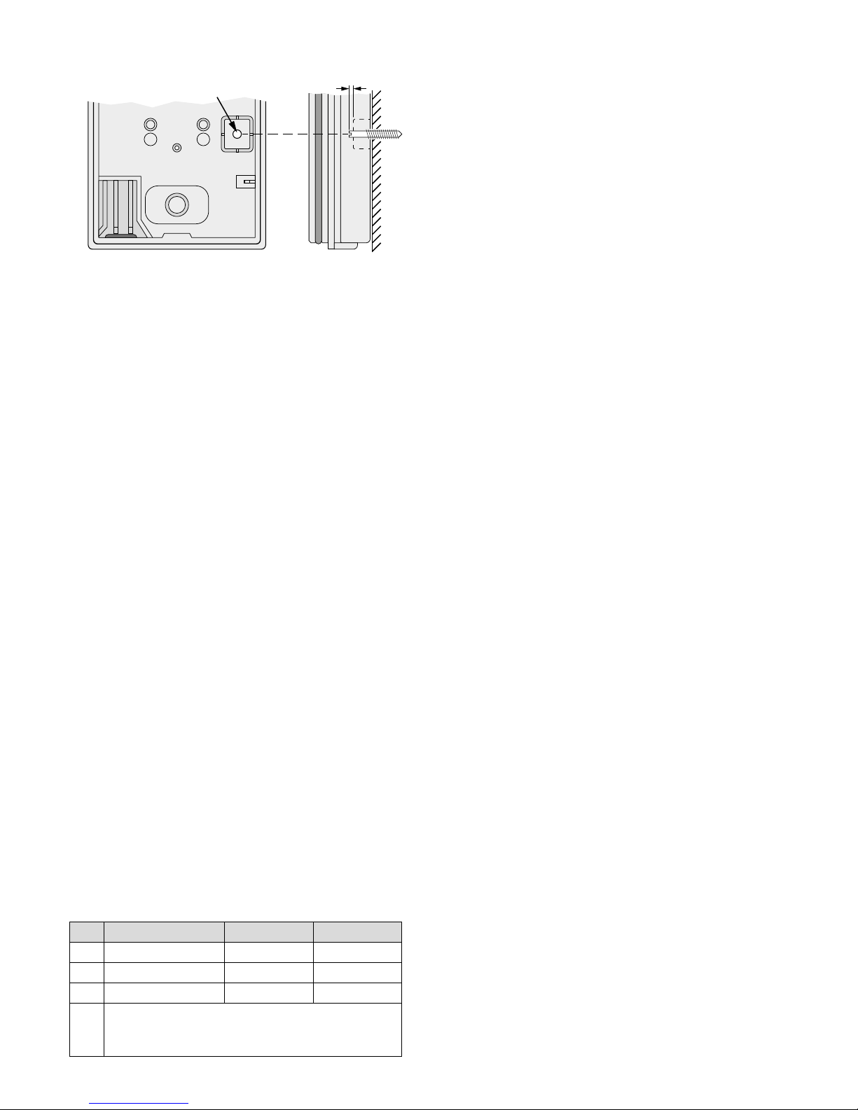
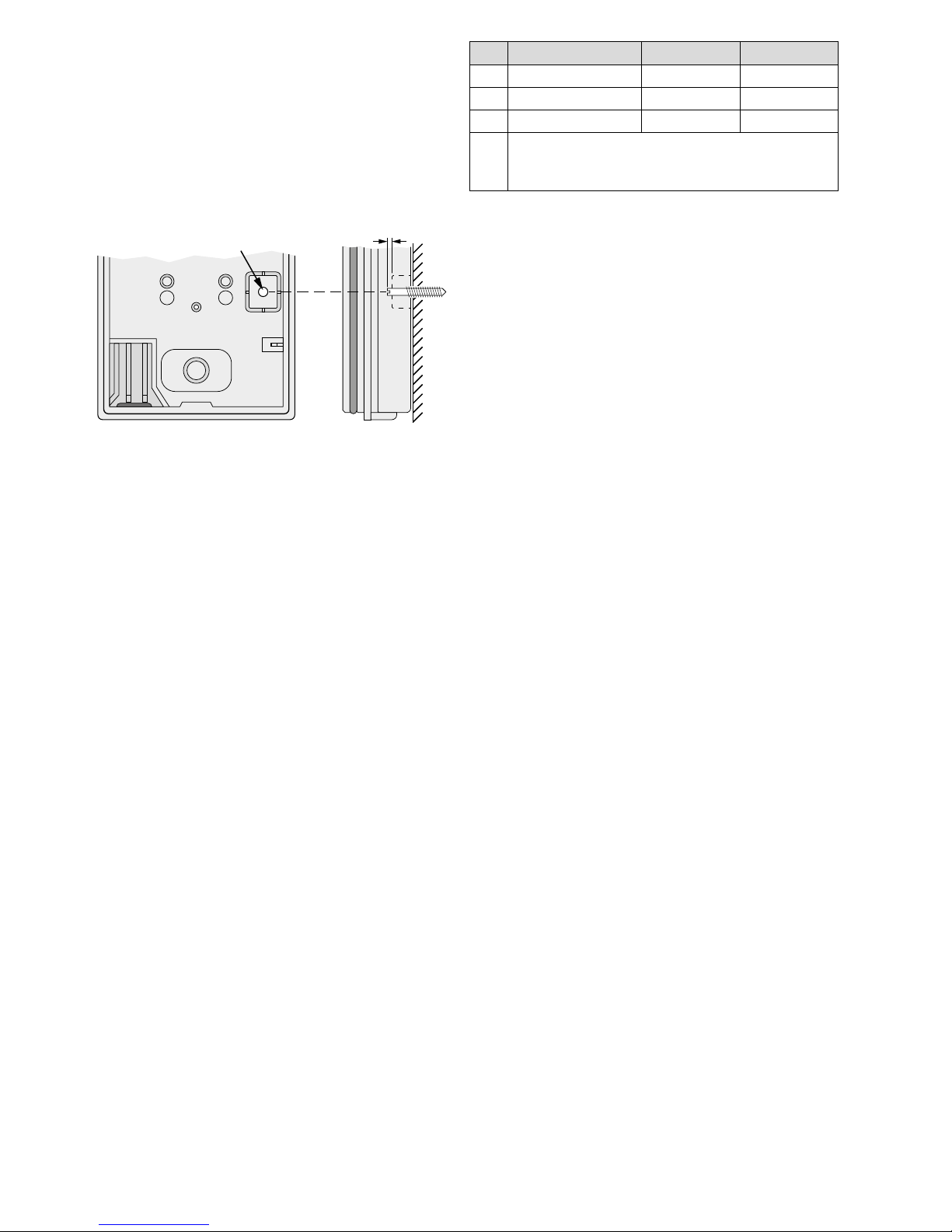
Cassez les 4 trous 6mm prédécoupés pour la fixa-
tion et un des deux trous 10mm pour le câble de
branchement. Pour le montage avec le support
mural SN-3, utilisez le trou 10mm inférieur pour
le câble.
Français
Français Page

9
Français
4)
Pour le montage avec le support mural, vissez
ce dernier sur le mur et vissez le détecteur sur le
support. Le contact anti-sabotage (10) ne peut
pas être utilisé ici ; il faut le désactiver en plaçant
un cavalier sur les pins WALL TAMPER (9).
5) Pour un montage directement sur le mur, dessi-
nez les trous de fixation et percez. Si le contact
anti-sabotage (10) doit être utilisé, dessinez un
trou (a) pour une vis sans tête et percez :
a
2 mm
6)
Maintenez la partie inférieure du détecteur contre
le mur et vissez la vis sans tête dans le mur jusqu’à
ce qu’elle dépasse de 2mm environ pour qu’elle
puisse fermer le contact anti-sabotage.
7)
Insérez la platine pour faire un test et tenez à
nouveau la partie inférieure contre le mur : le
contact doit déclencher de manière audible. Si
besoin, réglez avec précision la vis sans tête.
8) Fixez maintenant de manière définitive la partie
inférieure du détecteur au mur. Insérez la platine
et selon l’utilisation (chapitre 3.1), orientez verti-
calement et vissez.
3.3 Branchement et réglages
Avant de brancher, mettez la centrale d’alarme hors
fonction pour éviter qu’une alarme ne se déclenche.
1) Reliez la centrale aux bornes à vis (3) :
–contact alarme et anti-sabotage séparément :
contact alarme = bornes ALARM
contacts anti-sabotage = bornes TAMPER
–contact alarme et anti-sabotage comme boucle
d’alarme différentielle (schéma 2) : borne EOL
Mettez un cavalier sur les pins EOL (2). Sélec-
tionnez les valeurs pour les résistances R1 et R2
en mettant les cavaliers sur les pins R1 et R2 (1)
selon le schéma 2.
Si le contact anti-sabotage (10) n’est pas utilisé
(p.ex. si vous utilisez le support mural), mettez im-
pérativement un cavalier sur les pins WALL TAM-
PER (9) pour désactiver le contact anti-sabotage.
2) Reliez la tension d’alimentation 12V aux bornes
+ −.
3) Réglez les interrupteurs DIP (6) en conséquence.
NoFonction Position ON Position OFF
1 LED de contrôle (4) marche arrêt
2 Portée 12m 6m
3 Alarme pour 2 impulsions 1 impulsion
4
Dans des conditions difficiles (plantes/arbres bou-
geant à cause du vent, gros animaux dans la zone
de surveillance), mettez l’interrupteur sur ON.
3.4 Test de fonctionnement
1)
Pour contrôler le fonctionnement, mettez l’in-
terrupteur DIP N°1 sur ON pour que la LED de
contrôle (4) brille si un mouvement est détecté.
Fermez le détecteur avec le couvercle du boîtier,
allumez l’alimentation. 30 secondes environ plus
tard, la LED de contrôle arrête de clignoter, le
détecteur est prêt à fonctionner.
2) Lorsque la centrale d’alarme est désactivée, tra-
versez la zone de surveillance dans différentes di-
rections et surveillez la LED de contrôle : elle brille
brièvement si uniquement un des deux capteurs
déclenche ; elle brille plus longtemps en cas de
déclenchement d’alarme.
3) Si besoin, modifiez les réglages des interrupteurs
DIP 2– 4 (voir tableau ci-dessus).
4)
Après le contrôle de fonctionnement, mettez
l’interrupteur DIP N°1 sur OFF pour que la LED
de contrôle ne brille pas en cas de mouvement
détecté. Ainsi, la zone de surveillance ne peut
pas être espionnée lorsque la centrale d’alarme
est désactivée.
5) Enfin, faites un test de fonctionnement une fois
la centrale d’alarme activée.
4 Caractéristiques techniques
Portée :� � � � � � � � � � � � � � � � � 6 m ou 12 m, réglable
Angle de détection : � � � � � � � 90° (±45°)
Contact alarme : � � � � � � � � � � contact ouverture (NC)
Puissance :� � � � � � � � � � � � � 200mA/24 V (⎓) max�
Durée alarme :� � � � � � � � � � 2 s
Contacts anti-sabotage : � � � � contact ouverture (NC)
Puissance :� � � � � � � � � � � � � 40mA/30 V (⎓) max�
Alimentation tension continue :
10,5–13,8V
Courant de repos : � � � � � � � 14mA
Consommation si alarme : � 25 mA
Température fonc� : � � � � � � � � −30 à +55 °C
Boîtier :� � � � � � � � � � � � � � � � � ABS
Type protection : � � � � � � � � IP44
Dimensions : � � � � � � � � � � � 85 × 185 × 70mm
Poids :� � � � � � � � � � � � � � � � � � 265g
Tout droit de modification réservé.
Notice d’utilisation protégée par le copyright de MONACOR
®INTERNATIONAL GmbH & Co. KG. Toute reproduction
même partielle à des fins commerciales est interdite.

10
Italiano
Deutsch
Deutsch Seite
English
English Page
Français
Français Page
Español
Español Página
Nederlands
Nederlands Pagina
Polski
Polski Strona
Rivelatore di movimento a 2 zone
Queste istruzioni sono rivolte agli installatori con
conoscenze specifiche nella tecnica d’allarme. Vi
preghiamo di leggerle attentamente prima dell’in-
stallazione e di conservarle per un uso futuro.
1 Possibilità d’uso
Il rivelatore di movimento SOUTDOOR-L è stato rea-
lizzato in modo particolare per l’impiego in impianti
di videosorveglianza e d’allarme. È equipaggiato con
due sensori PIR singoli usati per il riconoscimento di
movimenti (collegamento AND di 4 secondi). Con
un movimento riconosciuto, il contatto NC d’allarme
si apre.
Per proteggere il rivelatore sono presenti due
contatti antisabotaggio che fanno scattare l’allarme
per mezzo della centralina d’allarme quando il con-
tenitore viene aperto o strappato dalla parete. I con-
tatti possono essere collegati separatamente con la
centralina d’allarme oppure in serie con resistori, a
scelta in serie o paralleli, come circuito d’allarme
differenziale (fig. 2).
2 Avvertenze importanti per l’uso
Il rivelatore è conforme a tutte le direttive rilevanti
dell’UE e pertanto porta la sigla .
•
Il rivelatore è protetto contro le intemperie (grado
di protezione IP44) ed è adatto per l’uso all’e-
sterno. La temperatura d’esercizio ammesso è
−30 a +55 °C.
•
Con il contenitore aperto, non toccare in nessun
caso la superficie dei sensori (5, 11) che potreb-
bero subire dei danni.
•
Per la pulizia del contenitore e delle lenti usare
solo detergenti delicati e un panno morbido, mai
prodotti chimici o mezzi aggressivi.
•
Nel caso d’uso improprio, d’installazione sbagliata
o di riparazione non a regola d’arte del rivelatore,
non si assume nessuna responsabilità per eventuali
danni consequenziali a persone o a cose e non si
assume nessuna garanzia per il rivelatore.
Se si desidera eliminare il rivelatore defini-
tivamente, consegnarlo per lo smaltimento
ad un’istituzione locale per il riciclaggio.
3 Installazione
3.1 Scelta delle lenti Fresnel
Dalla fabbrica sono integrate le seguenti lenti:
PIR1 con una lente per una tendina tridimensionale
PIR2 con una lente per una tendina orizzontale
Questa configurazione è consigliabile per la mag-
gior parte delle applicazioni con un ’altezza di
montaggio fra 1,8m e 2 m.
Per la sostituzione sono presenti quattro lenti:
1 lente per una tendina tridimensionale (A)
1 lente per una tendina orizzontale (B)
2 lenti per una tendina verticale (C)
I campi di sorveglianza possibili con le lenti sono
rappresentati a pagina 2.
Figg. 3– 5: PIR1 e PIR 2 con lenti per una tendina
tridimensionale; impostare l’angolo
verticale di rilevamento spostando il
circuito stampato
Fig. 6: PIR1 e PIR 2 con lenti per una tendina oriz-
zontale
Fig. 7: PIR1 e PIR 2 con lenti per una tendina ver-
ticale
Per ottenere un corridoio non sorvegliato per
animali, usare due lenti per una tendina orizzontale.
Montare il rivelatore di movimento a un’altezza fra
0,8m e 1,2 m e aggiustare il circuito stampato in
posizione centrale (Cap. 3.2, passo 8). In questo
modo, rimane non sorvegliato un settore per animali
di altezza fra 35cm circa e 2cm (fig. 6).
Per la sorveglianza di porte e finestre (fig. 8)
usare due lenti per una tendina verticale. Montare il
rivelatore di movimento a un’altezza fra 1m e 2m e
aggiustare il circuito stampato in posizione centrale.
In questo caso, l’angolo verticale di rilevamento è
di 90° (fig. 7).
Sostituire le lenti
1)
Allentare la vite in fondo al rivelatore di movi-
mento e togliere la parte anteriore del conteni-
tore.
2) Per staccare un portalente, spingere il nottolino
alla sua destra o sinistra verso l’esterno.
3) Togliere la lente e inserire la nuova lente.
4) Fissare a scatto il portalente.
3.2 Montaggio
Il rivelatore di movimento può essere avvitato diret-
tamente a una parete oppure può essere montato
con l’aiuto del supporto per parete orientabile e
inclinabile SN-3.
1)
Allentare la vite in fondo al rivelatore di movi-
mento e togliere la parte anteriore del contenitore.
2) Per togliere il circuito stampato svitare la vite nel
foro oblungo (7).
3)
Aprire i quattro fori prepunzonati di 6 mm nonché
uno dei due fori di 10mm per il cavo di collega-
mento. Nel caso di montaggio con il supporto
a parete SN-3 usare per il cavo il foro inferiore
di 10mm.
4) Nel caso di montaggio con il supporto a parete
avvitare lo stesso alla parete e avvitare il rivela-
tore sul supporto. In questo caso non è possibile
Italiano
Italiano Pagina

11
Italiano
utilizzare il contatto antisabotaggio (10) che deve
essere disattivato inserendo un ponticello sui pin
WALL TAMPER (9).
5)
Per il montaggio direttamente sulla parete se-
gnare il punto esatto e fare il foro. Se si vuole
sfruttare il contatto antisabotaggio (10), segnare
il punto per il foro (a) per una vite senza testa e
fare il foro:
a
2 mm
6)
Tener la vaschetta inferiore del rivelatore contro la
parete e avvitare la vite senza testo finché sporge
ancora di 2mm circa perché possa chiudere il
contatto antisabotaggio.
7) Rimettere il circuito stampato per un test e tener
la vaschetta inferiore nuovamente contro la
parete: si deve sentire che il contatto reagisce.
Eventualmente aggiustare con esattezza la vite
senza testa.
8) Solo allora fissare la vaschetta inferiore definiti-
vamente contro la parete. Rimontare il circuito
stampato e orientarlo in senso verticale secondo
l’applicazione (Cap. 3.1) e avvitarlo.
3.3 Collegamento e impostazioni
Prima del collegamento disattivare la centralina d’al-
larme per escludere che scatti un allarme.
1) Collegare la centralina con i morsetti (3):
–Contatti allarme e antisabotaggio separata-
mente:
Contatto allarme = morsetti ALARM
Contatti antisabotaggio = morsetti TAMPER
–Contatti allarme e antisabotaggio come circuito
d’allarme differenziale (fig. 2): morsetti EOL
Inserire un ponticello sui pin EOL (2). Scegliere i
valori per i resistori R1 e R2 inserendo i ponticelli
sui pin R1 e R2 (1) come illustra la fig. 2.
Se il contatto antisabotaggio (10) non viene
utilizzato (p.es. usando il supporto a parete),
occorre assolutamente inserire un ponticello sui
pin WALL TAMPER (9) per disattivare il contatto
antisabotaggio.
2) Collegare la tensione continua di 12V con i mor-
setti + − .
3) Impostare i dip-switch (6) secondo necessità:
N. Funzione Posizione ON Posizione OFF
1 LED di controllo (4) on off
2 Portata 12m 6m
3 Allarme con 2 impulsi 1 impulso
4
In caso di condizioni difficili (piante/alberi mossi
dal vento, animali grandi nella zona sorvegliata)
mettere lo switch so ON.
3.4 Test funzionale
1)
Per controllare le funzioni mettere il dip-switch n.1
su ON, perché il LED di controllo (4) si accenda
con un movimento rilevato. Chiudere il rivela-
tore con il coperchio del contenitore e accendere
l’alimentazione. Dopo mezzo minuto circa il LED
di controllo smette di lampeggiare e il rivelatore
è pronto per l’uso.
2)
Con la centralina d’allarme disattivata attraversare
la zona sorvegliata in varie direzioni osservando
il LED di controllo: si accende brevemente se re-
agisce solo uno dei due sensori; si accende più a
lungo se scatta un allarme.
3)
Se necessario cambiare le impostazioni dei
dip-switch 2– 4 (vedi tabella in alto).
4)
Dopo il controllo delle funzioni mettere il dip-
switch n.1 su OFF, perché il LED di controllo non
si accenda con un movimento rilevato e che sia
impossibile individuare la zona di rilevamento con
la centralina disattivata.
5) Per concludere effettuare un test funzionale con
la centralina d’allarme attivata.
4 Dati tecnici
Portata:� � � � � � � � � � � � � � � � � 6m o 12 m da impostare
Angolo di rilevamento:� � � � � � 90° (±45°)
Contatto d’allarme: � � � � � � � � di riposo (NC)
Potenza: � � � � � � � � � � � � � � max� 200 mA/24 V (⎓)
Durata dell’allarme: � � � � � � 2 s
Contatti antisabotaggio: � � � � di riposo (NC)
Potenza: � � � � � � � � � � � � � � max� 40 mA/30 V (⎓)
Alimentazione DC:� � � � � � � � � 10,5 – 13,8 V
Corrente di riposo: � � � � � � � 14 mA
Consumo corrente
con allarme:� � � � � � � � � � � � 25 mA
Temperatura d’esercizio: � � � � −30 a +55°C
Contenitore: � � � � � � � � � � � � � ABS
Grado di protezione: � � � � � IP44
Dimensioni: � � � � � � � � � � � � 85 × 185 × 70mm
Peso:� � � � � � � � � � � � � � � � � � � 265g
Con riserva di modifiche tecniche.
La MONACOR
®
INTERNATIONAL GmbH & Co. KG si riserva ogni diritto di elaborazione in qualsiasi forma delle presenti
istruzioni per l’uso. La riproduzione – anche parziale – per propri scopi commerciali è vietata.

MONACOR INTERNATIONAL GmbH & Co. KG • Zum Falsch 36 • 28307 Bremen • Germany
Copyright
©by MONACOR INTERNATIONAL. All rights reserved. A-1836.99.01.05.2017
Table of contents
Languages:
Other Monacor Security Sensor manuals

Monacor
Monacor IF-15 User manual

Monacor
Monacor IRS-200 User manual

Monacor
Monacor PIR-990 User manual

Monacor
Monacor MOUSE-09 User manual

Monacor
Monacor PIR-100D User manual

Monacor
Monacor S-230A User manual

Monacor
Monacor SMILE-16 User manual

Monacor
Monacor MOUSE-01 User manual

Monacor
Monacor PIR-100P User manual

Monacor
Monacor security MOUS-01 User manual
Popular Security Sensor manuals by other brands

Elkron
Elkron IR200 manual

aci
aci Carbon Dioxide Duct Series Installation & operation instructions

iNels
iNels Elko AirSF-100S quick start guide

Angelcare
Angelcare AC017 owner's manual

Ilmvac
Ilmvac biovac 106 Operation manual

System Sensor
System Sensor ECO1004TABLINK Installation and maintenance instructions