Page 5
the RESET button changes the digit being edited (blinking digit). Also when entering a data value, holding down the
RESET button and pressing the DOWN ()button will move the decimal place.
3.2.3 UP () and DOWN () BUTTONS
The UP and DOWN buttons can be used to view the current settings of the alarms. Press the UP button to
view LIMIT 1 or the DOWN button to view LIMIT 2. The display will revert back to normal after a few seconds.
When in the Menu, the UP and DOWN buttons are used to scroll through the menu options or edit data within
the options.
3.2.4 RECALL BUTTON
The RECALL button toggles between the maximum and minimum readings. The display will revert back to normal
after a few seconds. The RECALL button, when used with the RESET button, also resets the maximum and minimum
readings or total (when in Totalizing mode).
When in the Menu, the RECALL button reverts back one level without saving any changes () or exits the Menu
().
4.0 OPERATION
4.1 Modes of Operation –Channel 1
There are a number of different modes of operation. These modes determine what is shown on the display for any given
input to the instrument. Basically, it determines what computation is performed on the input. The input signals are on
Channel 1 (Signal inputs). The user can set the sense of the input, positive or negative. The AUXiliary input (Channel 2) can
be used to control the signals on Channel 1. Refer to Section 5.0 for details on changing modes.
NOTE: The instrument is programmed from the factory in the RPM Mode for one pulse per revolution.
4.1.1 RPM Mode
In the RPM Mode the unit behaves like a tachometer displaying revolutions (revs) per minute (RPM) from an input of
1 pulse per revolution. The instrument effectively multiplies the input frequency (pulses per second) by sixty to derive
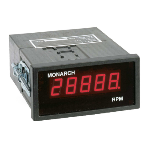
RPM. In this mode, the range of the unit is 5 to 999,990 RPM. The RPM LED on the bottom right of the display area
illuminates to indicate the RPM mode is programmed. The AUXiliary input (Channel 2) can be used to inhibit (disable)
the signal into the unit.
NOTE: For applications with more than one pulse per revolution, the Scale Mode (see below) must be used to
display RPM or other rates.
4.1.2 Frequency Mode
In the Frequency Mode, the unit displays input pulses per second or more commonly, Hertz (Hz). This is the most
basic mode of operation. The range of measurement in this mode is 0.0833 to 250,000 Hz. The AUXiliary input
(Channel 2) can be used to inhibit (disable) the signal into the unit
4.1.3 Scale Mode (Ratemeter)
In the Scale Mode of operation, the input frequency (pulses per second) is multiplied by a constant, which is set by the
user, and displayed. This allows the user to scale the input to obtain a read out in any units required: RPM, inches per
second, meters per hour, yards per fortnight, and so on. The scale factor may be set anywhere from 0.0001 to 99,999.
The AUXiliary input (Channel 2) can be used to inhibit (disable) the signal into the unit.
4.1.4 Single Event Capture (SECAP) Mode
The SECAP (Single Event Capture) Mode is just like the Scale Mode except that only one reading is made. The
RESET button is pressed to start each new measurement. The unit will then use the next input pulse to start a
measurement, then the next input pulse will end the measurement. In the other tachometer modes, the unit will keep
acquiring pulses until 10 mS (STD gate) or 1 mS (FAST gate) has passed so it can give an accurate reading. The
SECAP Mode sacrifices accuracy as measurements get shorter than 32 mS (STD gate) or 4mS (FAST gate), but it is
the only way to measure single (non-repeating) events. The AUXiliary input may be used for the second pulse input if
two sensors are used, the first pulse on Channel 1 will start the process and the second pulse on Channel 2 (AUX) will
stop the process. Refer to Appendix C - Using the Single Event Capture Mode.
4.1.5 Rate of Change (ROC) Mode
In the Rate of Change Mode, the unit displays the rate of change of the input frequency (pulses per second). The unit
measures the input frequency times the scale factor set by the user. A moment later it measures the input frequency
again. The difference of these two, scaled frequencies is divided by the time interval between the two measurements.
Several measurements are averaged then displayed.
The scale factor allows the user to scale the input to obtain a read out in any units required: RPM per Minute
(RPMPM), inches per second per second, meters per hour per minute, yards per fortnight per second, and so on. The
scale factor may be set anywhere from 0.0001 to 99,999.

