Monitor Audio Gold 50 User manual

owners manual


monitoraudio.com 1
Contents
Introduction 2
Main Features 2
Unpacking 3
Plinth Fixing 3
Spikes and Feet 4
For Wooden/Hard Floors 4
For Carpeted Floors 4
Grilles 4
Setting Up 5
2 Channel Positioning 5
AV Positioning 5
Setting up the Gold FX 6
Fixing the Gold FX to a wall 8
Connecting Speaker Cables 9
Bare Wire Connection 9
Banana Plugs 9
Wiring 9
Single Wiring 9
Bi-Wiring 10
Bi-Amping 10
TheEectsofBi-Wiring/Bi-Amping 10
Port bungs 11
Specications 12
OwnerInformation 13
ENGLISH

Gold Series2
Introduction
Born from the incredible success of the award winning GX Range, the new Gold Series furthar ne tunes its
distinguished qualities featuring new advanced driver technologies and materials amalgamated to form a
real world, yet truly esoteric speaker range. The Gold Series focuses on sonic clairty, detail and conveying
a truly honest expression of a recorded piece. Wether it be the epic cinematic soundscapes presented in a
movie, or the souring vocal melodies carried out by your favourite musical artist, the Gold Series will place
you in the moment as if you were there.
This astounding attention to detail is not only evident the sound of the new Gold but in every component part,
manufactured from only the nest materials and machined to exacting tolerances.
Main Features
• C-CAM® Ribbon transducer design – providing extension to a class leading 60kHz.
• New 5.5” and 6.5” bass drivers with C-CAM® cone – larger piston area oering higher eciency and
better dynamics.
• New 4” dedicated mid-range driver with C-CAM® cone and under-hung voice coil for very low distortion.
• New RST® Cone prole, for improved diaphragm rigidity and reduction in distortion.
• Die-cast Alloy chassis design for amazing rigidity and lower reection properties.
• HiVe® port technology oers for smoother air-ow for a superior transient response and tighter bass.
• Single bolt through driver systems, for increased overall bracing, rigidity and driver/bae de-coupling.
• Die-cast alloy terminal panel arrangement with high quality bi-wire terminals and high end spade type,
Pureow® Silver link cables.
• Pureow® Silver internal cabling.
• High quality crossovers with premium grade Polypropylene lm capacitors used throughout.
• Large radius cabinet edges provide low diraction and smoother overall frequency response.
• Curved cabinet prole for increased rigidity and reduced internal standing waves.
• Hand selected premium quality wood veneer (dark walnut) or high gloss piano nishes (black, white
or ebony).
• Rigid 20mm MDF construction throughout, employing both radial and cross-bracing techniques for high
rigidity and ensuring low cabinet colouration.
• Invisible magnetic grille xing oers clean visual styling when used without the grille.
• Full 3-way design (Gold 200, 300 & Gold C350).
• Die-cast alloy plinth structures and adjustable feet with provision for both hard and carpet oors (Gold
200 and 300 only).

Unpacking
Ensure there is plenty of clean oor area around where you are proposing to unpack the loudspeakers.
Remove any lose components from the packaging (feet, bolts, plinths, grilles etc) and invert the carton. Lift
the carton up and remove the packaging end cap. Remove the tape from the bag(s)revealing the bottom of
the cabinet(s).
With the Gold 50 and Gold 100, stand the cabinets upright and remove the remaining packaging end cap and
bag(s). Place the cabinets on the stands and position them according to instructions on page 5.
With the Gold 200 and Gold 300, t the plinths and feet before proceeding any further.
Plinth Fixing
(Gold 200 & 300 only)
Fit the plinths and spiked feet to the base of each speaker. Refer to page 4.
The plinths are provided for stability as well as improving the acoustic performance of the speakers. Due
to the tapered shape of the cabinets, it is not recommended to install them without the plinths tted as the
speakers are likely to be unstable.
Plinth Bolt
Spike
Foot
Plinth
Lock Nut
Washer
Locking nut
ENGLISH
monitoraudio.com 3

Spikes and Feet
For Wooden/Hard Floors
(Gold 200 & 300 only)
The foot comes pre-assembled for use on hard/solid oors or where spikes are
inappropriate. All that is required is xing them into the plinths. This is achieved
by screwing the feet fully into the 2 threaded holes in each half of the plinth.
With great care turn the cabinet the right way up. Place the cabinet in the desired
location, checking that it is level on all sides. If slightly o-level, unscrew the
foot at the lowest point and check again. Continue this process until the cabinet is
fully level. Use the locking nuts (illustrated on page 3) on each foot to x the feet
in place and to stop any unwanted vibrations.
For Carpeted Floors
(Gold 200 & 300 only)
If being installed on carpeted oors, remove the spike from the packaging and x
it into the foot assembly, as illustrated.
Please ensure there are no hidden wires under the carpet that could be damaged
by the spikes.
With great care turn the cabinet the right way up. Place the cabinet in the desired
location, checking that it is level on all sides. If slightly o-level, unscrew the
foot at the lowest point and check again. Continue this process until the cabinet is
fully level. Use the locking nuts (illustrated on page 3) on each foot to x the feet
in place and to stop any unwanted vibrations.
Grilles
The grilles are held invisibly in place by magnets in the cabinet itself (except Gold FX).
When tting, rstly ensure they are the correct orientation (badge at the bottom) and oer them up to the
cabinet. The magnets should them pull them into position, but it may need some ne adjustment to ensure
they are square on the cabinet.
The Gold FX comes with the grilles factory tted. When removing them, carefully prise them away from the
cabinet with the tips of your ngers. There are three separate grilles tted to each Gold FX cabinet.
CAUTION: Always remove the grilles before attempting to move or lift the loudspeakers.
Gold Series4

Setting Up
2 Channel Positioning
When arranging a 2 channel system, the listening position and the loudspeakers should form an equilateral
triangle. The speakers should be positioned approximately 6 - 10 feet (1.8 - 3m) apart. The ideal distance
from the rear wall varies depending on the speaker (see list below), however, they need to be a minimum of
3 feet (91cm) from the side walls.
• Gold 50 and Gold 100 8 - 18 inches (20 - 45cm)
• Gold 200 18 - 24 inches (45 - 60cm)
• Gold 300 upto 36 inches (91cm)
Experimentation is strongly advised when initially setting up the speakers, as environment and personal
preference dier with every installation. If there is insucient bass for example, try moving your speakers
closer to a wall. The opposite approach is recommended if there is excess bass. Also see the information
on page 11 refering to Port Bungs. If stereo imaging is being lost, try ‘toeing’ them in slightly. The sound
should appear to originate from the centre point between the speakers, not the actual speakers themselves.
AV Positioning
On pages 7 and 8, there are illustrations showing optimal positioning and some example room layouts for
AV applications.
The front, and in some cases rear, oor standing and stand mount speakers should be positioned approx 6 - 9
feet apart (1.8m - 2.5m) and start with them about 10 inches (25cm) from the wall.
If the sound is too bass heavy or there is bass boom from the room when playing music (without a subwoofer),
try moving the loudspeakers slightly further away from the wall(s) or adjusting the crossover frequency
settings for the speakers and/ or sub. Also try changing the subwoofer’s position. If this is not possible, then
try the supplied port bungs (not included in the Gold FX or Centre). Refer to Page 11.
The Gold Centre channel should be positioned so they are pointing at the viewing position and at approximate
ear height. If it is below or above ear height, use some rubber feet (small feet supplied) to angle it slightly.
The Gold FX’s should be positioned in accordance with the below illustrations and instructions, and approx 2
feet (60cm) to the bottom of the speaker above ear height when in your listening position.
NOTE: When using 2 pairs of Gold FX in a 7.1 system, set the rear surround left speaker to ‘Right’
and the rear surround right to ‘Left’. This is required due to tweeter phasing. All four speakers need
to be set to di-pole mode.
ENGLISH
monitoraudio.com 5

Setting up the Gold FX
The Gold FX’s are independent speakers that can be tailored to be either left or right handed at the ick of
a switch. Likewise, they can be operated in either di-pole or mono-pole modes. The default factory setting
is mono-pole.
In mono-pole mode, only the main driver and tweeter will be active. In di-pole mode, the main tweeter is
disengaged and the side drivers and tweeters are active. The front ring tweeters are out of phase with the
other tweeter and mid/bass unit. It is recommended to implement this conguration when using two pairs
Gold FX as part of a 7.1 channel system, with the Gold FX’s taking up positions on side and rear walls. Please
note, it is essential they are positioned correctly when used in a 7.1 channel system. Please refer to the
switch positioning images on pages 7 and 8.
NOTE: Before adjusting any switches, please ensure that the amplier is at the very least
turned o. This will help to protect the amplier.
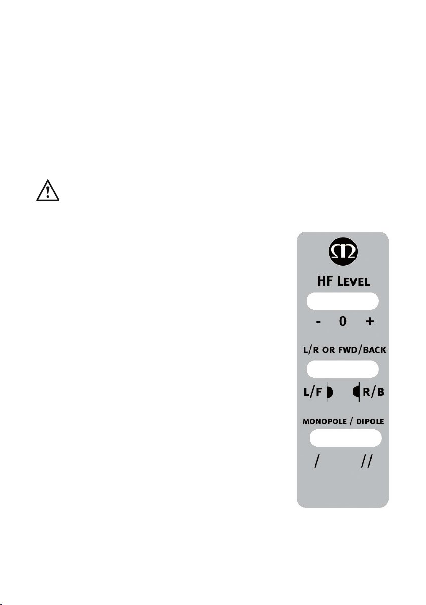
Tweeter Attenuation Switch: This switch adjusts the level of the main high
frequency tweeter unit. In the middle position, there is no attenuation. Placed
in the ‘-’ position, the high frequencies will be attenuated by 3dB.Placed in the
‘+’ position, the high frequencies will be boosted by 3dB.
Location Switch:This switch is used when determining the location of the Gold
FX’s. Please refer to the illustrations on pages 7 & 8 for correct positioning.
This will only make a dierence when in ‘di-pole’ mode.
Mono-pole/ Di-pole Switch: This switch determines the actual mode of
the Gold FX. When part of 5.1 systems as a rear speaker, set the switch to
mono-pole. Although there is nothing wrong with experimenting and trying
the switch in the di-pole mode. If part of a 7.1 system as side speakers, set the
switch to di-pole. If using 4 Gold FX’s (side and rear) set them all to di-pole
mode. Please see the illustrations on pages 7 & 8 to determine the setting of
the ‘Location Switch’ depending on system set up.
If you are using the 12v trigger, set the switch to monopole mode. The trigger
will switch a relay to enable the di-pole mode.
12 volt Trigger: (Not shown) This feature is present on some AV ampliers. It
is possible to customise the 12v trigger to switch the speakers to di-pole for
certain sources. For example, multi-channel music should be listened to in
mono-pole mode, however, movies should be listened to in di-pole mode. This
feature automates the switching between the two modes. Please refer to your
AV amplier manual for further instruction.
Gold Series6

44 - 60°
90 - 110°
5.1 system with
surround speakers
on the side wall. Floor
standing/ stand mounting
speakers can also be used.
44 - 60°
135 -150°
5.1 system with surround
speakers on the rear wall. Floor
standing/ stand mounting speakers can
also be used.
ENGLISH
monitoraudio.com 7

Fixing the Gold FX to a wall
CAUTION: Always determine where the Gold FX will be xed and the structure of the wall. For
safety reasons, if unsure of your ability to provide a secure and safe xing, do not attempt to x
these speakers to a wall. Instead, please obtain the services of a competent and qualied trades
person.
CAUTION: Ensure that water pipes or electricity cables do not run behind where the wall plate is
going to be secured. Work from secure steps and avoid trailing wires.
NOTE: We do not supply wall xing screws and plugs with the Gold FX. Please only use suitable
xings for the type of wall construction the Gold FX’s will be xed to.
To x the Gold FX’s to a wall, we would recommend using the wall xing template provided within the
packaging carton. Fix the wall plate to the wall, connect the speaker cables, and 12v trigger cables (if being
used) and hang the cabinet on the wall plate.
90 - 110°
44 - 60°
7.1 system with Gold FX’s
for surround and rear surround.
Floor standing/ stand mounting
speakers can also be used.
135 -150°
Gold Series8

Connecting Speaker Cables
Bare Wire Connection
Unscrew the binding posts and pass the bare wire through the through-hole. Tighten the binding post to
clamp the wire in place.
Banana Plugs
Remove the red and black plastic plugs from the terminals and insert the banana plugs into the standard
4mm holes that are revealed. Pliers may be required to gain purchase on the plugs.
Wiring
Single Wiring
Single wiring is acheived via a single set of cables to the terminals on the back of the loudspeaker. Internally
the loudspeaker crossover guides the frequencies to the appropriate driver/tweeter. Low frequencies to the
bass drivers, mid frequencies to the mid/bass drivers and high frequencies to the tweeter.
It is perfectly acceptable to connect to the top, bottom terminals or even diagonally (experimentation is
advisable to achieve the preferred results).
NOTE: When using this method you must KEEP the terminal links in place.
LEFT
+
-
RIGHT
AMP
+
-
ENGLISH
monitoraudio.com 9

Bi-Wiring
Bi-wiring is accomplished by connecting separate pairs of speaker cables to the terminals on the loudspeaker
from a single pair of connections on the amplier. In the case of the Gold Series, the bottom terminals
connect to the bass driver(s) and the top terminals connect to the tweeter in 2 way loudspeakers, or the mid
and tweeter in 2.5 and 3 way loudspeakers.
NOTE: When using this method the terminal links MUST be removed.
Bi-Amping
Bi-Amping is the same as Bi-Wiring except you are introducing a second amplier into the equation.
In order to Bi-Amp you must connect a set of speaker cables to the top terminals on the loudspeaker from
one amplier and another set of speaker cables to the bottom terminals from the second amplier.
NOTE: When wiring this method the terminal links MUST be removed.
TheEectsofBi-Wiring/Bi-Amping
Fundamentally a loudspeaker crossover varies the impedance seen by the speaker and by the power
amplier. The situation is such that when the full range musical signal is applied to the terminals of a full-
range speaker system,the bass driver(s) only receives low frequency signals, the mid driver receives the mid
band frequency signals and the tweeter only gets sent high frequency signals. This means that if separate
speaker cables are connected to the low frequency terminals, and the high frequency terminals, not only
have the drive units and the frequency’s directed and divided for them, but the two separate speaker cables
will now also carry dierent signals, the bass cable mostly the lows, and the tweeter cable mostly the highs.
Once the high and low frequencies have been separated in this fashion, the strong current pulses and surges
demanded by bass drivers when reproducing bass or drums, will not interact with the delicate sounds of a
ute or cymbal.
LEFT
+
-
RIGHT
AMP
+
-
LEFT
+
-
RIGHT
AMP
+
-
LEFT
+
-
RIGHT
AMP
+
-
Gold Series10

In a single wired system, unwanted mechanical and electrical resonances manifest as distortion at both
sets of speaker terminals. Due to the impedance of the speaker cables, these distortions will not be entirely
cancelled by the amplier. Instead, they modulate between the two crossovers, and degrade sound quality.
When bi-wiring, this interaction is minimised as signal distortion is ‘seen’ at the amplier’s output where it
can be more eectively cancelled. Bi-wiring/ bi-amping therefore presents a ‘cleaner’ signal at both the low
frequency and high frequency speaker terminals, and because the high and low frequencies have already
been separated, each has a minimal eect on the other - in essence the bass does not overpower delicate
treble.
In terms of the audible benet, bi-wiring/ bi-amping, provides more clarity and detail to the midrange and
high frequencies. Often the bass will become faster and tighter. Focus and staging will improve as well. In
all, this is a very eective and desirable improvement and is highly recommended by Monitor Audio.
Port bungs
WARNING: Care must be taken not to insert the port bungs too far into the port, as this may result
in the foam bung being lost inside the cabinet.
If the loudspeaker is to be installed in a small room, typically 9 sqM (80 sqFT), or a room known to reproduce
accentuated bass response, it may be desirable to t port bungs. However, experimentation is recommended
with positioning of the loudspeaker in the room prior to tting. To optimise performance from the loudspeaker
it is important to ensure the loudspeaker is not positioned too close to a wall or near the corners of a room
(refer to the suggestions on page 5).
If the positioning of the loudspeaker is predetermined by room aesthetics or layout, or you nd you have
accentuated bass, please move on and read point 1 for the Gold 50/ Gold 100 and point 2 for the Gold 200/
Gold 300.
1. Where stand-mount speakers (Gold 50 & Gold 100) are to be sited in close proximity (less than 8
inches/ 20cm) to a rear wall (such as on a bookshelf, positioned in a cabinet or on a stand close to
a wall), we recommend tting port bungs to the ports. This will reduce the bass ‘boom’ sometimes
termed as overhang, and assist the loudspeakers to reproduce their best performance under these
environmental conditions. ‘Boom’ is generally caused when bass energy from the loudspeaker ‘excites’
room modes and causes an accentuation at a particular frequency, or number of frequencies.
2. Where oor-standing loudspeakers (Gold 200 & Gold 300) are to be sited in close proximity (closer than
18 inches/ 45cm) to a rear wall, we recommend tting the port bungs. This will reduce the bass ‘boom’
sometimes termed as overhang and assist the loudspeakers to reproduce their best performance under
these environmental conditions. This is caused when bass energy from the loudspeaker ‘excites’ room
modes and causes an accentuation at a particular frequency, or number of frequencies.
When tting port bungs the overall bass extension will not be reduced, however bass energy/ output
around the port tuning frequency will be reduced. This has the eect of reducing bass ‘boom’ while
increasing bass clarity and apparent agility.
In all circumstances experimentation is highly recommended.
ENGLISH
monitoraudio.com 11

Specications
Gold 50 Gold 100 Gold 200 Gold 300 Gold C150 Gold C350 Gold FX
System Format 2 Way 2 Way 3 Way 3 Way 2 Way 3 Way 2 Way
Frequency Response 55Hz – 60kHz 42Hz – 60kHz 35Hz – 60kHz 30Hz – 60kHz 55Hz – 60kHz 40Hz – 60kHz 60Hz – 60kHz
Sensitivity (dB)
1W@1m 86 88 89 90 89 90 87
Nominal Impedance
(ohms) 8888888
Maximum SPL (dBA) 109.8 112.6 114.5 116.8 111.5 113.8 110.8
Power Handling - RMS
(W) 100 120 150 200 150 200 100
Recommended
Amplifier
Requirements (W)
50 - 100 60 - 120 100 - 150 100 - 200 100 - 150 100 - 200 50 - 100
Bass Alignment Bass Reflex.
HiVe® port system
Bass Reflex.
HiVe® port system
Bass Reflex.
HiVe® port system
Bass Reflex.
HiVe® port system Sealed Cabinet Sealed Cabinet Sealed Cabinet
Crossover Frequency 2.3kHz 2.7kHz L.F - M.F: 400Hz
M.F - H.F: 2.6kHz
L.F - M.F: 790Hz
M.F - H.F: 2.3kHz 2.8kHz L.F - M.F: 800Hz
M.F - H.F: 2.3kHz
Bi-Pole: 2.3kHz
Di-pole: 2.6kHz
Drive Unit Compliment
1 x 5.5” RST®
bass / mid driver
1 x C-CAM® ribbon
H.F transducer
1 x 6.5” RST®
bass / mid driver
1 x C-CAM® ribbon H.F
transducer
2 x 5.5” RST® bass driver
1 x 4” RST®
mid-range driver
1 x C-CAM® ribbon
H.F transducer
2 x 6.5” RST® bass driver
1 x 4” RST®
mid-range driver
1 x C-CAM® ribbon H.F
transducer
2 x 5.5” RST® bass driver
1 x C-CAM® ribbon H.F
transducer
2 x 6.5” RST® bass driver
1 x 4” RST®
mid-range driver
1 x C-CAM® ribbon H.F
transducer
1 x 6.5” RST® bass driver
2 x 4” C-CAM®
mid-range driver
1 x C-CAM® ribbon
H.F transducer
2 x 25mm Gold C-CAM®
dome tweeter
Cabinet Dimensions
H x W x D
mm (inches)
300 x 170 x 263
11 13/16 x 6 11/16 x 10 3/8
362 x 210 x 303
14 3/8 x 8 1/4 x 11 15/16
951 x 170 x 300
37 7/16 x 6 11/16 x 11 13/16
1060 x 210 x 330
41 3/4 x 8 1/4 x 13
172 x 461 x 303
6 11/16 x 18 1/8 x 11 15/16
254 x 581 x 333
10 x 22 7/8 x 13 1/8
310 x 390 x 160
12 3/16 x 15 3/8 x 6 5/16
Complete Dimensions
Inc Terminals, Plinths
& Spikes
H x W x D
mm (inches)
300 x 170 x 290
11 13/16 x 6 11/16 x 11 7/16
362 x 210 x 330
14 3/8 x 8 1/4 x 13
995 x 274 x 370
39 3/16 x 10 13/16 x 14 9/16
1105 x 317 x 370
43 1/2 x 12 1/2 x 14 9/16
172 x 461 x 330
6 11/16 x 18 1/8 x 13
254 x 581 x 360
10 x 22 7/8 x 14 3/16
310 x 390 x 168
12 3/16 x 15 3/8 x 6 5/8
Product Weight
kg (Ibs) 7.5 (16lb 8oz) 9.9 (21lb 12 oz) 22.2 (48lb 14oz) 27.2 (59lb 14oz) 6 (13lb 4 oz) 19.6Kg (43lb 2oz) 11.9 (26lb 2oz)

OwnerInformation
Product Details
Model
Product Serial No
Date of Purchase
Dealer Details
Dealer Name
Address
e-mail address
Telephone Number
Monitor Audio reserves the right to alter specications without notice.
For the 5 years manufacturer’s warranty, please visit the online registration form at:
www.monitoraudio.com
ENGLISH
monitoraudio.com 13

manuel utilisateur
Gold Series14

FRANCAIS
Table des matières
Introduction 16
Caractéristiques principales 16
Déballage 17
Fixation du socle 17
Pointes et pieds 18
Pour sols durs et parquets 18
Pour sols moquette 18
Grilles 18
Installation 19
Positionnement à 2 canaux 19
Positionnement de l'AV 19
Installation du Gold FX 20
Installation de l'enceinte Gold FX à un mur 22
Connexion des câbles des haut-parleurs 23
Connexiondulnu 23
Fiches banane 23
Câblage 23
Câblage unique 23
Bi-câblage 24
Bi-amplication 24
Leseetsdubi-câblageetdelabi-amplication 24
Bouchons de port 25
Spécications 26
Informationsutilisateur 27
monitoraudio.com 15

Introduction
Née du succès colossal de la célèbre gamme GX, la nouvelle série Gold va plus loin dans la dénition et
les performances. Ces haut-parleurs dotés des dernières technologies et des derniers matériaux de pointe
forment une gamme à la fois sobre et performante. La série Gold met l'accent sur la clarté sonore, le détail
et le rendu optimal et honnête d'un morceau enregistré. Que ce soient pour les environnements sonores
épiques d'un lm ou les mélodies vocales de votre artiste préféré, la série Gold vous fait vivre le moment
comme si vous y étiez.
L'incroyable attention portée aux détails ne se ressent pas uniquement sur le son, mais aussi sur chaque
composant de ces enceintes, fabriquées avec les meilleurs matériaux dans le strict respect des tolérances.
Caractéristiques principales
• Le transducteur à ruban C-CAM® apporte une extension de la bande passante dans les hautes fréquences
jusqu'à 60kHz.
• Les nouveaux haut-parleurs de grave 5,5” et 6,5”à cône C-CAM® orent une plus grande zone de piston
pour une ecacité optimale et une meilleure dynamique.
• Nouveau haut-parleur medium 4” dédié avec cône C-CAM® et bobine vocale assurant une distorsion
ultra basse.
• Nouveau cône RST® réduisant fortement la distorsion et améliorant la rigidité du diaphragme.
• Nouveau châssis en polymère améliorant la rigidité et diminuant les propriétés de réexion.
• Technologie de port HiVe® accélérant le transit de l'air dans le cabinet et créant des graves beaucoup
plus dynamiques.
• Haut-parleurs xés par une seule vis traversante («single bolt-through») pour un renforcement et une
rigidité optimisés, et un meilleur découplage du haut-parleur.
• Panneau de terminal en polymère avec terminaux-bi-câblage et cosses de qualité supérieure.
• Câblage interne argent Pureow®.
• Crossover de haute qualité et condensateurs en polypropylène améliorant la clarté.
• Caisson aux extrémités larges pour une faible diraction et une réponse en fréquence plus uide.
• Prol de caisson incurvé pour une rigidité améliorée et des ondes stationnaires internes réduites.
• Bois véritable de qualité supérieure sélectionné à la main (noyer foncé) ou nitions noir piano brillant
(noir, blanc ou ivoire).
• Construction imposante en MDF de 20mm, avec renforts internes pour consolider la rigidité du cabinet
et éviter les colorations sur le cabinet.
• Fixations magnétiques invisibles de la grille pour un design net et épuré lorsque celle-ci est retirée.
• Conguration trois voies (Gold 200, 300 & Gold C350).
• Structure des socles et pieds en polymère pour les sols durs et les sols moquette (Gold 200 et 300
uniquement).
Gold Series16

FRANCAIS
Boulon de
socle
Pointe
Pied
Socle
Rondelle
d'écrou
Écrou de
serrage
Déballage
Vériez que l’espace est dégagé à l’endroit où vous souhaitez déballer les haut-parleurs. Retirez tous les
composants libres de l’emballage (pieds, boulons, socles, grilles, etc.) et retournez le carton. Soulevez
le carton et retirez le capuchon d’emballage. Retirez la bande du(des) sac(s) pour révéler le bas du(des)
caisson(s).
Pour les modèles Gold 50 et Gold 100, posez les caissons debout, puis retirez les capuchons et sachet(s)
d’emballage restants. Placez les caissons sur les socles et positionnez-les selon les instructions indiquées
en page19.
Pour les modèles Gold 200 et Gold 300, installez les socles et les pieds avant de continuer.
Fixation du socle
(Gold 200 & 300 uniquement)
Installez les socles et les pieds à pointe à la base de chaque haut-parleur. Voir page18.
Les socles permettent de stabiliser et d’améliorer les performances acoustiques des haut-parleurs. En
raison de la forme conique des caissons, il n’est pas conseillé de les installer sans les socles. Cela pourrait
déséquilibrer les haut-parleurs.
monitoraudio.com 17

Pointes et pieds
Pour sols durs et parquets
(Gold 200 & 300 uniquement)
Les pieds sont pré-assemblés pour une utilisation sur les sols durs et parquets
ou si les pointes ne peuvent être utilisées. Il sut de les xer sur les socles. Pour
cela, vissez les pieds sur les 2 trous letés situés sur le dessous de chaque socle.
Remettez le cabinet en place avec précaution. Placez le cabinet à l’endroit désiré,
puis vériez qu’il est bien équilibré sur tous les côtés. S’il n’est pas correctement
à plat, dévissez légèrement le pied par le bas puis vériez à nouveau. Continuez
ce procédé jusqu’à ce que le cabinet soit parfaitement équilibré. Utilisez l’écrou de
serrage (illustré en page17) sur chaque pied pour le maintenir en place et éviter
les vibrations indésirables.
Pour sols moquette
(Gold 200 & 300 uniquement)
Si vous installez vos haut-parleurs sur des sols moquette, retirez la pointe de
l’emballage et xez-la sur l’assemblage du pied, comme illustré.
Vériez qu’aucun câble électrique susceptible d’être endommagé par le pied ne
passe sous le tapis ou la moquette.
Remettez le cabinet en place avec précaution. Placez le cabinet à l’endroit désiré,
puis vériez qu’il est bien équilibré sur tous les côtés. S’il n’est pas correctement
à plat, dévissez légèrement le pied par le bas puis vériez à nouveau. Continuez
ce procédé jusqu’à ce que le cabinet soit parfaitement équilibré. Utilisez l’écrou de
serrage (illustré en page17) sur chaque pied pour le maintenir en place et éviter
les vibrations indésirables.
Grilles
Les grilles sont maintenues en place par des aimants situés sur le cabinet (sauf sur le Gold FX).
Pour les installer, vériez d’abord leur orientation (l’insigne en bas) et posez-les sur le cabinet. Les aimants
les mettront naturellement en place, mais il peut être nécessaire d’eectuer quelques réglages pour
s’assurer du bon positionnement sur le cabinet.
Les grilles du Gold FX sont préalablement installées. Lorsque vous les enlevez, retirez-les délicatement du
cabinet avec le bout de vos doigts. Trois grilles diérentes sont installées sur chaque cabinet Gold FX.
ATTENTION: retirez toujours les grilles avant de déplacer ou soulever les haut-parleurs.
Gold Series18
This manual suits for next models
6
Table of contents
Languages:
Other Monitor Audio Speakers System manuals

Monitor Audio
Monitor Audio Radius User manual

Monitor Audio
Monitor Audio MASS Satellite User manual

Monitor Audio
Monitor Audio Bronze Series User manual

Monitor Audio
Monitor Audio Shadow 50 User manual

Monitor Audio
Monitor Audio VECTA V240 User manual

Monitor Audio
Monitor Audio Silver 1 User manual

Monitor Audio
Monitor Audio Bronze Series User manual