Monmouth Scientific Cleanroom Kit 4M User manual

Issue 03 –June 2018 1
Cleanroom Kits

Issue 03 –June 2018 2
Installation Guide

Issue 03 –June 2018 3

Issue 03 –June 2018 4
Guide Contents
Introduction: ...........................................................................................................................................6
Tools that you will need:..................................................................................................................... 6
Safety & Disclaimer Notice ................................................................................................................. 7
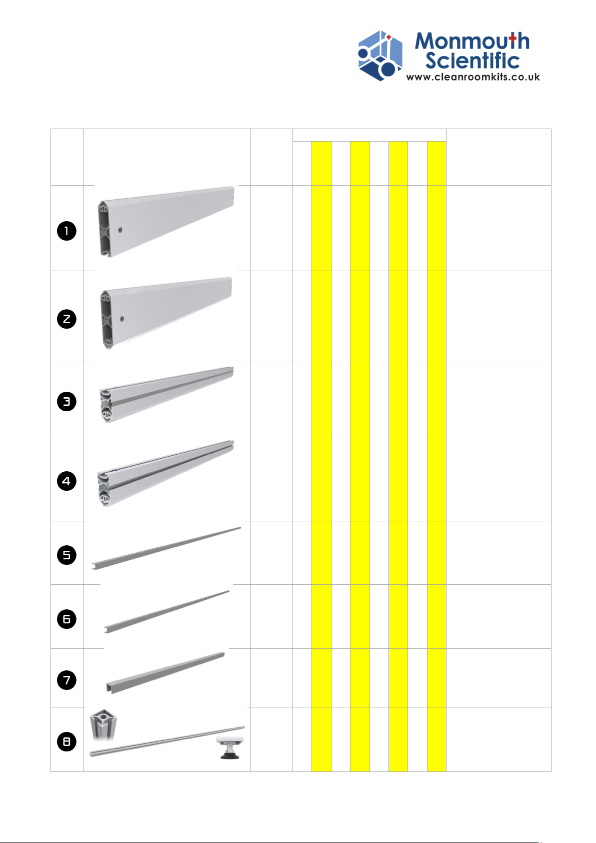
Complete Parts List ................................................................................................................................. 8
Unions? .................................................................................................................................................15
Union Parts........................................................................................................................................15
How does the Union Work?..............................................................................................................16
The Union in the Monmouth Cleanroom: ............................................................................................ 17
Joining two pieces:................................................................................................................................19
Fitting a panel: ...................................................................................................................................... 21
Fitting a ceiling tile support: .................................................................................................................23
Standard Wall Panel..............................................................................................................................24
Door Panels...........................................................................................................................................25
Door ......................................................................................................................................................26
Ceiling Assembly ...................................................................................................................................27
4M –2m x 2m room.......................................................................................................................... 27
4Mplus –2m x 2m room with 1m x 2m atrium ................................................................................28
6M –3m x 2m room.......................................................................................................................... 29
6Mplus –3m x 2m room with 1m x 2m atrium ................................................................................30
9M –3m x 3m room.......................................................................................................................... 31
9Mplus –3m x 3m room with 1m x 3m atrium ................................................................................32
12M –4m x 3m room........................................................................................................................33
12Mplus –4m x 3m room with 1m x 3m atrium ..............................................................................34
Using CAM1000 in 9M, 9M+, 12M & 12M+...................................................................................... 35
Top Door Runner Assembly ..................................................................................................................36
Hanging the door(s) .......................................................................................................................... 37
Bottom Door Runner Assembly ............................................................................................................38
Soft Close Door Adjustment..................................................................................................................39
Room Assembly.....................................................................................................................................41
WARNINGS........................................................................................................................................41
Installing Clean Air Modules (CAM) ......................................................................................................47
CAM1000...........................................................................................................................................48
Introduction ......................................................................................................................................48
Installation ........................................................................................................................................49
Setting the fan speed ....................................................................................................................50
Maintenance .....................................................................................................................................51

Issue 03 –June 2018 5
Changing the pre-filters ................................................................................................................51
Changing the HEPA filter............................................................................................................... 51
CAM1000 Replacement Filter Part Numbers................................................................................51
CAM2250...........................................................................................................................................52
Introduction ......................................................................................................................................52
Installation ....................................................................................................................................53
System Set-up ...............................................................................................................................54
CAM Module Connections ............................................................................................................54
Setting the fan speed ....................................................................................................................55
Calibration of the low-airflow alarm............................................................................................. 56
Maintenance .....................................................................................................................................56
Changing the pre-filters ................................................................................................................56
Replacement filter part numbers..................................................................................................56
Colour Coded Aluminium Framework –without panels ......................................................................57
4M –2m x 2m room 4Mplus –2m x 2m room with 1m x 2m atrium..................................57
6M –3m x 2m room.......................................................................................................................... 58
6Mplus –3m x 2m room with 1m x 2m atrium ................................................................................59
9M –3m x 3m room.......................................................................................................................... 60
9Mplus –3m x 3m room with 1m x 3m atrium ....................................................................................61
12M –4m x 3m room........................................................................................................................62
12Mplus –4m x 3m room with 1m x 3m atrium ..............................................................................63
Complete Cleanroom Layouts - ............................................................................................................64
4M –2m x 2m room 4Mplus –2m x 2m room with 1m x 2m atrium ..................................64
6M –3m x 2m room.......................................................................................................................... 65
6Mplus –3m x 2m room with 1m x 2m atrium ................................................................................66
9M –3m x 3m room.......................................................................................................................... 67
9Mplus –3m x 3m room with 1m x 3m atrium ....................................................................................68
12M –4m x 3m room........................................................................................................................69
12Mplus –4m x 3m room with 1m x 3m atrium ..............................................................................70
Questions and Support .........................................................................................................................71

Issue 03 –June 2018 6
Introduction:
IMPORTANT: PLEASE READ AND UNDERSTAND THESE
INSTRUCTIONS IN FULL BEFORE STARTING ANY ASSEMBLY.
Welcome to the Cleanroom Kits installation guide. This document will take you through the set-up
and installation of your cleanroom. Please remember that handing of doors is possible and that
positions of doors, windows and lights are all interchangeable so it is impossible to give a ‘screw by
screw’ account of every permutation.
It is important that you FULLY understand how each section of the room goes together as this will
help you in planning the exact layout of your room. Therefore, PLEASE READ AND UNDERSTAND
THESE INSTRUCTIONS IN FULL BEFORE STARTING ANY ASSEMBLY.
Please check all the parts are present and familiarise yourself with them. There are occasional
necessary subtle differences between parts and it is important they are not used in the wrong
locations. Lengthy errors can be avoided by understanding the system.
Assembly of the room is a two person process –do not attempt to build the room on your own.
Significant injury can occur when lifting or moving heavy parts. Construction time of the room will
vary depending upon expertise and room size. Please do not rush and ensure you understand the
process at each stage. If in doubt, ask!
Start with a clear area and make sure you have enough space to install the cleanroom including
enough height.
Make sure you have all the necessary tools available and adhere to all safety instructions when using
tools or devices. We recommend using safety glasses at all times when assembling the room.
When lifting the CAM (Clean Air Modules) into place on the ceiling, you must ensure the structure is
complete and fully tightened prior to placement. We also strongly recommend the use of a suitable
lifting device such as a Genie lift (can be hired from any good tool shop) to minimise the risk of
personal injury or damage to the product.
Tools that you will need:
4mm Allen Keys (2no. provided)
3mm Allen Key (provided)
White Faced Rubber Mallet (provided)
Safety Glasses –to be worn at all times
10mm & 13mm spanners
Suitable ladders
Lifting Device
Spirit Level
Tape Measure
Clear Silicone (Optional)
Silicone Gun (Optional)

Issue 03 –June 2018 7
Safety & Disclaimer Notice
In order to assemble this room you must be fully competent in all tasks associated with assembly.
All personnel must be suitably trained in the use of any equipment used during the installation of
this Cleanroom Kit. It is the customer’s responsibility to ensure the safety of all colleagues and
personnel carrying out this task. Monmouth Scientific Limited does not accept responsibility for any
injury or damage howsoever caused.
Any electrical work necessary should be carried out by a qualified electrician.
If at any time, you are not comfortable with any aspect of the
installation then STOP and seek professional assistance.
Monmouth Scientific can provide free-of-charge support on
the telephone by calling +44 1278 458090 during normal
office hours or will happily provide an installation service.
Please contact us for a quotation if you wish to use the
installation service.

Issue 03 –June 2018 8
Complete Parts List
Number on
drawings:
Length
Qty
Monmouth
Part No.
4M
4M+
6M
6M+
9M
9M+
12M
12M+
Lower Wall Bar
970mm
7
10
9
12
11
15
13
17
30100-PA-970
Mid Wall Bar
970mm
7
10
9
12
11
15
13
17
30100-2PA-970
Top Wall Bar with side filler strip
970mm
8
10
10
12
12
14
14
16
3050-PA-FS-970
Top Wall Bar (for internal walls)
970mm
0
2
0
2
0
3
0
3
3050-PA-970
Plastic Reducer Strip
1045mm
26
36
34
44
42
56
50
64
PP-02371-1045
Plastic Reducer Strip
735mm
2
4
2
4
2
4
2
4
PP-02371-735
Plastic Reducer Strip
205mm
4
8
4
8
4
8
4
8
PP-02371-205
Corner Post with foot
2350mm
3
3
3
3
3
3
3
3
3030C-FT-2350

Issue 03 –June 2018 9
Number on
drawings:
Length
Qty
Monmouth
Part No.
4M
4M+
6M
6M+
9M
9M+
12M
12M+
Double faced post with foot
(& additional 25mm slot)
2350mm
3
3
5
5
7
7
9
9
3030D-S-FT-2350
Double faced post with foot
(& two additional 25mm slots)
2350mm
0
0
0
0
0
1
0
1
3030D-2S-FT-2350
Double faced post with foot and door
runner
(& additional 25mm slot)
2350mm
1
1
1
1
1
1
1
1
3030D-S-FT-2350
Double faced post with foot and door
runner
(& two additional 25mm slots)
2350mm
0
1
0
1
0
1
0
1
3030D-2S-FT-2350
Single Faced Post with foot
2350mm
0
2
0
2
0
2
0
2
3030S-FT-2350
Outer Door Post with foot
2350mm
1
1
1
1
1
1
1
1
3060-FT-2350

Issue 03 –June 2018 10
Number on
drawings:
Length
Qty
Monmouth
Part No.
4M
4M+
6M
6M+
9M
9M+
12M
12M+
Main Ceiling Beam (full width of room)
1970mm
1
1
2
2
0
0
0
0
3050-FS-1970
Main Ceiling Beam (full width of room)
2970mm
0
0
0
0
0
0
0
0
3050-FS-2970
Main Reinforced Ceiling Beam (full width of
room)
3024mm
0
0
0
0
2
2
3
3
3050-FS-2970/30100-
3030
Standard Ceiling Beam 0° Connectors
970mm
2
2
2
2
2
2
4
4
3050-FS-970-0
Standard Ceiling Beam 90° Connectors
970mm
0
1
0
1
0
2
0
2
3050-FS-970-90
Standard Ceiling Beam (with alternate
connectors 1no. 0° & 1no. 90° Connector)
970mm
1
1
2
2
4
4
4
4
3050-FS-970-0/90
Ceiling Support Rail
919.5mm
8
12
12
16
16
22
22
28
MW-04473-919.5
Ceiling Support Rail
969.5mm
4
8
8
12
16*
22*
22*
28*
MW-04473-969.5
*If ISO 8 CAM1000
selected then 4no. less
will be provided and
substituted with 4no.

Issue 03 –June 2018 11
Number on
drawings:
Length
Qty
Monmouth
Part No.
4M
4M+
6M
6M+
9M
9M+
12M
12M+
Ceiling Support Rail
622mm
4
4
4*
4*
0
0
0
0
MW-04473-419.5
(*only with CAM1000 in
ISO8 6M or 6M+)
Ceiling Support Rail
469.5mm
0
0
4*
4*
0
0
0
0
MW-04473-622
(*only with CAM2250 in
ISO7 6M or 6M+)
Ceiling Support Rail
1072
mm
0
0
0
0
4*
4*
4*
4*
MW-04473-419.5
(*only with CAM1000 in
ISO8 9M,9M+, 12M or
12M+)
Door Header - slotted
970mm
1
2
1
2
1
2
1
2
30100-PA-970SL
Door Rail Support - slotted
970mm
1
2
1
2
1
2
1
2
30100-2PA-970SL
Door
1995mm
x
1000mm
1
2
1
2
1
2
1
2
Door
Door Runner
1960mm
1
2
1
2
1
2
1
2

Issue 03 –June 2018 12
Number on
drawings:
Length
Qty
Monmouth
Part No.
4M
4M+
6M
6M+
9M
9M+
12M
12M+
Door Runner Cover & end caps
1970mm
1
2
1
2
1
2
1
2
Standard White Wall Panel
1042mm
x 980mm
11
15
14
18
17
22
20
25
Standard Clear Window Panel
1042mm
x 980mm
2
3
3
4
4
6
5
7
Clear Window Panel –adjacent to door
731mm x
980mm
1
2
1
2
1
2
1
2
Part Clear Window Panel
980mm x
203mm
2
4
2
4
2
4
2
4
Standard White Ceiling Panel
960mm x
960mm
2
4
4
6
8*
11*
11*
**
14*
**
*If ISO 8 CAM1000 selected
then 2no. less will be
provided and substituted
with 2no.
**If 2no. CAM2250 are
selected then 1no. less
will be provided
Standard White Ceiling Panel with LED light
and associated transformers and leads.
960mm x
960mm
Optional –supplied as ordered.
For each light ordered
one less ceiling tile
will be supplied.

Issue 03 –June 2018 13
Number on
drawings:
Length
Qty
Monmouth
Part No.
4M
4M+
6M
6M+
9M
9M+
12M
12M+
White Ceiling Panel
960mm x
612mm
2
2
2*
2*
0
0
0
0
(*only with CAM1000 in
ISO8 6M or 6M+)
White Ceiling Panel
960mm x
460mm
0
0
2*
2*
0
0
0
0
(*only with CAM2250 in
ISO7 6M or 6M+)
White Ceiling Panel
960mm x
1112mm
0
0
0
0
2*
2*
2*
2*
(*only with CAM1000 in
ISO8 9M,9M+, 12M or
12M+)
Socket Head Button Screw –M5x12mm
12
24
12
24
12
24
12
24
For use with door
brackets
Channel T-Nut –M5
12
24
12
24
12
24
12
24
For use with door
brackets
5mm washer
12
24
12
24
12
24
12
24
For use with door
brackets
Spare 0° Union
5
5
5
5
5
5
5
5
Spare 90° Union
5
5
5
5
5
5
5
5
End Caps
30mm
x100mm
0
0
0
0
4
4
4
4
30100EC
Union Cover Stickers
Sheet of
15
3 x
15
5 x
15
4 x
15
5 x
15
4 x
15
6 x
15
5 x
15
7 x
15
Electrical Trunking
1200mm
1
1
1
1
1
1
1
1

Issue 03 –June 2018 14
Number on
drawings:
Length
Qty
Monmouth
Part No.
4M
4M+
6M
6M+
9M
9M+
12M
12M+
CAM1000 Clean Air Module with support
brackets (4) and power leads
ISO8
1
1
1
1
1
1
1
1
K-CAM1000
ISO7
1
1
0
0
0
0
0
0
CAM1000 Control Panel
ISO8
1
1
1
1
1
1
1
1
ISO7
1
1
0
0
0
0
0
0
CAM2250 Clean Air Module with support
brackets (4) and power leads
ISO8
0
0
0
0
0
0
0
0
K-CAM2250
*Optionally 2no.
ISO7
0
0
1
1
1
1
1*
1*
CAM2250 Control Panel
ISO8
0
0
0
0
0
0
0
0
ISO7
0
0
1
1
1
1
1
1
4mm Allen Key (Colours vary)
4mm
2
2
2
2
2
2
2
2
3mm Allen Key (Colours vary)
3mm
1
1
1
1
1
1
1
1
White Rubber Mallet
1
1
1
1
1
1
1
1

Issue 03 –June 2018 15
Unions?
The unions are the 4 part connectors that provide the basis for joining the aluminium extrusions
making up your cleanroom. There are two primary different union types, one at 0˚ and one at 90˚.
A third ‘double’ union (to join mitres) is used on the doors, but the
doors are pre-assembled for your convenience.
Union Parts
Each primary union consists of 4 parts:
m8 grub screw
11.8mm Ø barrel
Spring
10mm Ø draw bar
When assembled, the point of the grub screw must locate into the indent in the draw bar so the
correct orientation of the drawbar is essential.
0˚Union
90˚ Union

Issue 03 –June 2018 16
How does the Union Work?
The unions all work in the same way. When the union is assembled into the aluminium correctly, the
grub screw is tightened which pushes the point of the grub screw into the dimple on the draw bar
and pulls the head of the drawbar toward the end of the Aluminium profile. This traps the adjoining
profile into position. Small teeth in the underside of the head of the bar aid this process by gripping
into the adjoin profile.
m8 grub screw
11.8mm Ø barrel
Spring
10mm Ø draw bar

Issue 03 –June 2018 17
The Union in the Monmouth Cleanroom:
Every joint of two aluminium profiles follows the same principle. In most (if not all) the union is
supplied fitted into the Aluminium profile, however for the sake of clarity we will describe how to fit
a union into the Monmouth profile.
1.
Take the aluminium profile with a 12mmØ hole.
2.
Fit the barrel into the 12mmØ hole with the
barrel cross-hole parallel to the hole in the
aluminium profile.
3.
Place the spring over the draw bar and insert
them both into the aluminium and push through
the barrel.
4.
Push the draw bar in against the spring and
ensure dimple on the side of the draw bar is
visible in the hole of the barrel.

Issue 03 –June 2018 18
5.
Insert the grub screw and using a 4mm allen hex
key, tighten the grub screw.
6.
When the point of the grub screw enters the
dimple of the barrel, you can release the barrel
and it will stay assembled.
7.
You should only tighten the grub screw so that at
least 3mm of draw bar is visible behind the head
of the fixing.
8.
It is quite possible to over tighten making
attachment to the next piece of aluminium
impossible. In this case relax the grub screw until
at least 3mm of draw bar is visible.

Issue 03 –June 2018 19
Joining two pieces:
There are two simple methods of joining the aluminium using the union:
1.
The first is to slide the aluminium into place
down the connector.
2.
Slide to the desired position. Be careful to keep
both pieces square as you may mark the
aluminium.
3.
4.
This second method is ideal when both ends of a piece need to locate into uprights.
Line up the head with the slot at 90° from the required position and push in so the head can rotate
freely in the slot.

Issue 03 –June 2018 20
5.
Then rotate the whole piece back 90° slowly into
the required position. Be careful to keep both
pieces square as you may mark the aluminium. If
the piece will not easily rotate, relax the grub
screw slightly.
6.
Hold the two pieces in the desired position
7.
And tighten the grub screw to draw the two
pieces together. Please ensure that the two sides
are flush when being drawn together for the
best joint.
8.
This manual suits for next models
3
Table of contents
Other Monmouth Scientific Laboratory Equipment manuals

Monmouth Scientific
Monmouth Scientific Circulaire HLFT1000 Installation and operation manual

Monmouth Scientific
Monmouth Scientific Ductaire TITAN DT1000 Installation and operation manual

Monmouth Scientific
Monmouth Scientific Circulaire PCB1800 Installation and operation manual

Monmouth Scientific
Monmouth Scientific CT675 Installation and operation manual

Monmouth Scientific
Monmouth Scientific PCR650 Operating instructions

Monmouth Scientific
Monmouth Scientific Ductaire Pro DP700 Installation and operation manual

Monmouth Scientific
Monmouth Scientific Circulaire FB250 Installation and operation manual