Montana VKT User manual

Instruction manual
for pedal-assist
bicycle

Introduction
Thank you for choosing our product. Before using the
bicycle, we recommend that you read the "Usage and
Maintenance" booklet provided to you as well as this
specific EPAC booklet very carefully. The latter contains all
the specific technical and safety information for the
electrical components; you can find all the necessary
information relating to the mechanical parts in the Usage
and Maintenance Booklet.
Regulatory Requirements
Meets European Directive 2001/95/EC
Commission Decision 2015/681/EC
Meets international standard
EN ISO 4210 (1 to 9):2014
EPAC is the acronym adopted by European Standard UNI EN15194:2012:
“Electrically Power Assisted Cycle”
The functional characteristics of EPACs required by Italian and European
regulations are:
- The electric motor provides assistance only when the cyclist is
pedalling in a forward direction
- The assistance stops when the cyclist stops pedalling in a
forward direction

- The assistance gradually decreases and eventually stops when
the vehicle reaches the maximum speed of 25 km/h
Before using your bicycle
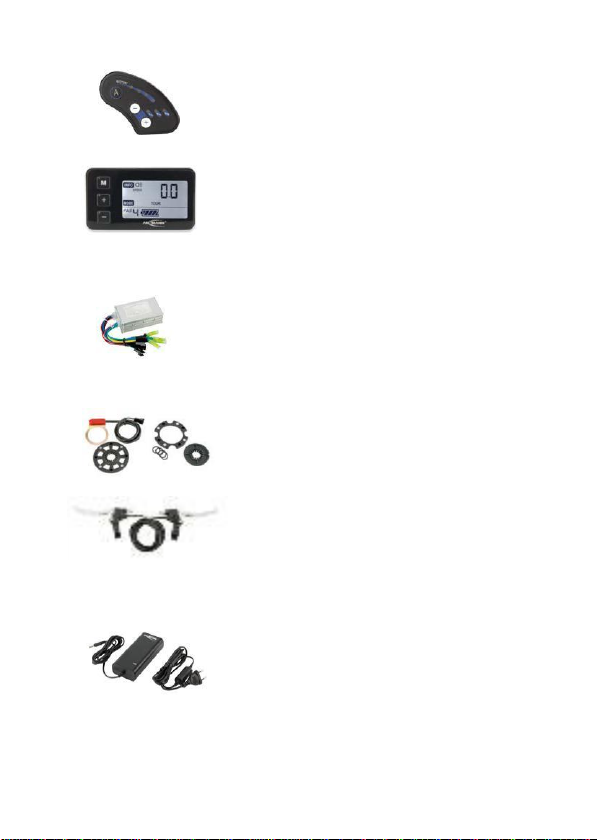
Before using your EPAC, carefully examine all its parts
and components using the manual that you will find
attached to your bicycle for reference.
Specifically, please ensure that:
a) the tyres are inflated to the correct level
b) the brakes work properly
c) the various screws and bolts are sufficiently
tight
d) the saddle and handlebars are adjusted as
necessary
e) the lights work properly
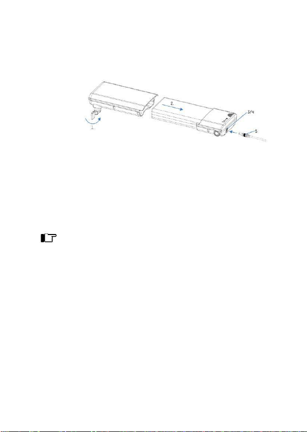
f) the battery is positioned correctly in the
housing provided and is fixed to the frame
using the safety lock
g) the battery is charged
If you have any doubts or issues, please contact your
dealer.
While using your EPAC, we strongly recommend that
you comply with the traffic laws of the country in which
you are located.

We advise you not to carry out any maintenance work
on parts or components, nor to dismantle them,
particularly
the electrical parts. Should this be necessary, you are
advised to consult your dealer.
Original spare parts must be used.
It is dangerous to cycle through deep puddles, which
may form on the roadway in the event of heavy rain.
Water may enter the engine/hub or other electrical
components, causing short circuits and irreparable
damage.
Do not touch electrical contacts. Do not allow
metal parts of terminals to come into contact; this will
avoid electrical discharges that could cause burns
and/or damage to the battery or other electrical parts.

Quick-Start Guide to use your electric pedal-assist
bicycle immediately
The bike is supplied with the battery not fully charged. You must
therefore charge the battery first.
Charge the battery for the first time using the charger
provided. First, connect the charger cable to the battery
and then insert the charger
plug into a 220 V / 50 Hz socket.
Once the battery is fully charged (when the charger LED turns
green), disconnect the charger plug from the mains and then
remove the cable from the battery. It is very important that you
never carry out these steps in reverse order to avoid
damaging the battery.
To maximise the range of your battery, you must fully
charge and discharge it three times to activate its
internal chemistry.
Place the battery back on the bicycle, ensuring that it is sitting
correctly in its housing, and lock it in place with the key.

SYMBOLS USED
Warning: symbol indicates possible danger and risk, including
potential personal injury.
Symbol indicates that the user must perform an operation or
adjustment.
These symbols will appear in the remainder of this manual with no further
explanation.
COMPONENTS OF THE ELECTRICAL
SYSTEM
RM5.0 36 V / 250 W REAR MOTOR
10INR18/65-4 FLAT 36 V BATTERY with
calibration/adjustment capabilities, charging
socket, housing with safety lock and box for
control unit/controller

LED DISPLAY WITH BUTTONS for motor
control, handlebar positioning and assist level
selection
OR
LCD DISPLAY with buttons for motor control,
handlebar positioning, speedometer functions,
battery charge display and assist level selection
36 V / 12 A MOTOR CONTROLLER/CONTROL
UNIT
PEDAL SENSOR with magnet(s)
BRAKE LEVER for mechanical brakes complete
with cut-off for motor disconnection (where
available)
ORIGINAL ANSMANN CHARGER for 36
Vbattery

HOUSING FOR
RACK-MOUNTED BATTERY
The housing for the rack-mounted battery and the box for the control unit
are supplied together with the luggage rack. The cables to connect the
control unit are already assembled inside the battery housing. The
luggage rack must be attached to the bicycle in the appropriate position,
as shown in the instructions.
control unit box
battery
housing/box
connectors for the
safety lock
battery
rods to be mounted
to frame
points to be
secured
to frame
USING THE BATTERY AND
CHARGER
Fully charge the battery before using it for the first time!!! The battery
can be charged while mounted to the bike, or separately. The lock is
used to fix the battery to the bicycle in the correct position. If it is not
fixed in place, it could be damaged and/or stolen. Turn the lock to
remove the battery.

To remove the rack-mounted battery, first open the lock by turning it
anti-clockwise (1), then push the battery out of its casing/housing. Once
you have placed the battery back in its case, turn the safety lock
clockwise to lock it in place and prevent it from falling out or being
stolen.
To charge the battery, open the cap (3) on the socket (4) and connect
the charger (5).
After connecting the charger to the battery, connect the charger to the
electrical outlet. The charger LED flashes red while the battery is
charging; once it is charged, the LED turns green. A flashing LED on the
battery's capacity indicator also indicates that charging is taking place
( only on the down tube battery).
Temperature:
from 0°C to
45°C
Charging time:
Approx. 5/7
hours
(depending on the
battery's
capacity)
Storage
temperature:
from 5°C to
25°C
(recommended)
Storage
temperature:
-20°C to 45°C
(max. limits)
We recommend that you recharge the battery after each use. If you are
not planning to use the battery for a long period of time (e.g. during
winter), charge it completely before storing it. To avoid damage to the
battery, recharge it every 12 weeks. Store it in a dry place and observe
the temperatures indicated above.

Avoid direct sunlight and excessive temperatures
max. 60°C
Keep the battery away from fire
CE mark (conformity): this battery is built in line with
European standards
The cells contain lithium
Li-ion
Do not dispose of as household waste. Dispose of at an
authorised waste collection point
Use only original Ansmann chargers to charge the
battery
Avoid short circuits
While charging, place the battery on an inflammable and heat-
resistant surface. There should be no flammable or
combustible objects nearby
Never leave the battery unattended while charging
Batteries are not a toy - Keep out of reach of children!
The original Ansmann cables and sockets must not be cut or
modified under any circumstances!

Improper use may lead to explosion,
overheating or fire. Using this product incorrectly and failing to
follow the instructions provided in this manual may result in
defects or premature wear. Keep the instruction manual in a
safe place and always hand it over along with the battery.
After charging the battery, unplug the charger from the electrical outlet and
disconnect it from the battery. Close the battery socket cap to prevent water
from entering and avoid corrosion.
The battery has a capacity indicator to allow you to check the charge level.
Tap the button on the capacity indicator. The charge level is briefly displayed
by means of LEDs that illuminate. While riding, you can check the battery
charge level on the handlebar display (the devices need to be calibrated, so
the charge shown on the display may be different from the level displayed by
the battery indicator).
CONNECTIONS
The controller/control unit is the central component of the electrical system.
The various components, including the motor, display, brake levers, battery
and pedal sensor, must be connected to the control unit as per the following
electrical diagram. Each connector is a different shape and/or size to avoid
incorrect connections. Only the motor cables need to be connected based on
their colours. Ensure that all cables are connected correctly and securely to
avoid malfunctions caused by a lack of contact.
The control unit and all the cables must then be stored inside the control unit
box. Optional: the light module can be connected to the L3 (power) terminal.


START-UP
Once the battery is fully charged and securely fixed in the support case
or the luggage rack box, the electrical system is ready to be used.
POWER ON/OFF
For the rack-mounted battery, use the battery's ON/OFF button to
switch the system on. To switch off the system, press the OFF button
on the battery.
ON/OFF
If your system comes with the LED display, the riding features can be
selected from this display.
The display shows the LEDs indicating the battery charge level and the
motor assist level. All the features can be selected using the 3 buttons
on the display.

initial assist
button (6
km/h)
assist level
selection
buttons
flashing LED = assist level 1
fixed LED = assist level 2
flashing LED = assist level 3
fixed LED = assist level 4
flashing LED = assist level 5
fixed LED = assist level 6
When the system is switched on by turning on the battery, the assist
level is automatically set to 2. Using the ''+'' and ''-'' keys, the motor
assist level can be changed from zero (no assistance) or from 1 to the
maximum of 6. Depending on the chosen level, the motor will turn at a
different speed. If you press the "A'' button, the motor will assist you up
to 6 km/h without the need to pedal (initial assist feature) for as long as
you continue to hold down the button.
LCD DISPLAY
If your system comes with the LCD display, the riding features can be
selected from this display. The LCD display is equipped with a
speedometer feature.
You can select the assist level and the speedometer features using the
3 buttons on the display.

backlight indicator speedometer indicators
speedometer features
assist level
selection
initial assist (6 km/h)
motor assist level battery charge level
When the system is switched on by turning on the battery, the assist
level is automatically set to 2. Using the "+" and "-" keys, the motor
assist level can be changed from zero (no assistance) or from 1 to the
maximum of 6.
assist level 0 = PAS 0
assist level 1 = PAS 1
assist level 2 = PAS 2 / ECO
assist level 3 = PAS 3 / CITY
assist level 4 = PAS 4 / TOUR
assist level 5 = PAS 5 / POWER
assist level 6 = PAS 6 / BOOST
The motor will turn at different speeds depending on the assist level. If
you hold down the "-'' button, the motor will assist you up to 6 km/h
without the need to pedal until you release the button. Pressing the "+''
button for a few seconds activates/deactivates the backlight. Tapping
the "M'' button allows you to cycle through the speedometer features:
SPEED, AVERAGE SPEED, MAXIMUM SPEED, ODOMETER,
DISTANCE, JOURNEY TIME. When the system is switched on, the
speed is automatically selected.

The precise speed and precise number of kilometres travelled are
displayed after you have selected the correct wheel size before using
the bicycle.
By pressing the "-'' and ''+'' keys simultaneously for a few seconds, you
will enter the Settings mode (turn on the system first). The first
parameter that can be adjusted is the brightness of the backlight by
pressing ''-'' or ''+'' (bl - 1, bl - 2,bl - 3). Tapping the "M" button will take
you to the wheel settings (wheel size in mm). The flashing values can be
selected using the ''-'' and ''+'' keys. Tapping the "M'' button will allow
you to set the next value. The wheel to be selected must correspond to
the size of the wheel used (spin the wheel and measure the distance
with a tape measure). You can exit the Settings menu by holding down
the "M" key for longer than a few seconds. When you exit the menu,
your changes are automatically saved.
LIGHTS (OPTIONAL)
As previously described in the CONNECTIONS section, the system is
compatible with the Ansmann light module. This light module already has
the connectors set up for connection to the control unit. You can then
connect the front and rear lights to the light module directly (LUXURY
VERSION).
To turn the lights on, use the switch on the front light.

MOTOR ASSIST
Turning on the battery turns the system on. Level 2 is automatically
selected, but this can be changed at any time (even before you begin
riding). The motor provides assistance only while the rider is pedalling
(this is a legal requirement). However, when the 6 km/h initial assist is
activated, the motor does provide assistance without the need to pedal.
Selecting the assist level selects the motor speed, up to a maximum of
25 km/h.
If you are not used to the bicycle and have not yet familiarised
yourself with it, we advise that you start pedalling with the level
at zero, i.e. with no motor assist. Once you feel safe on the
bicycle, you can then select an assist level above zero.
Thanks to the motor's freewheel, you can use the bicycle with the
electric system (pedelec) like a normal bicycle, i.e. without the battery or
with the battery switched off. Additional force when pedalling is not
required.

TECHNICAL SPECIFICATIONS
MOTOR
brushless DC (with gear)
Voltage
36 V
Current
max. 12 A
Power
250 W (continuous rated power)
400 W (peak power)
Control
6 assist levels up to a max. of 25 km/h
initial assist up to 6 km/h
Torque
up to 30 Nm
BATTERY
Lithium-ion battery
Model
10INR18/65-4 or 10INR18/65-5
Charge
from 10.4 Ah to 11.6 Ah
Cells
18650 type
CHARGER
lithium-ion charger, CC/CV system
Input
100-240 V AC
Input
42 V DC, 1.35 A

ACCESSORIES/SPARE PARTS
To ensure that the bicycle and the electric riding system remain safe and reliable, only use
original Ansmann accessories and spare parts intended for this purpose. All the necessary
accessories and parts are included with the bicycle. Spare parts can be purchased later in
the event of wear or loss.
NOTES

WARRANTY CERTIFICATE
Buyer details
First name:
Surname:
Address:
Postcode, city:
Telephone:
Email:
Bicycle details
Model:
Colour/Size:
Frame number:
Motor number:
Battery number:
shop stamp
Table of contents
Other Montana Bicycle manuals