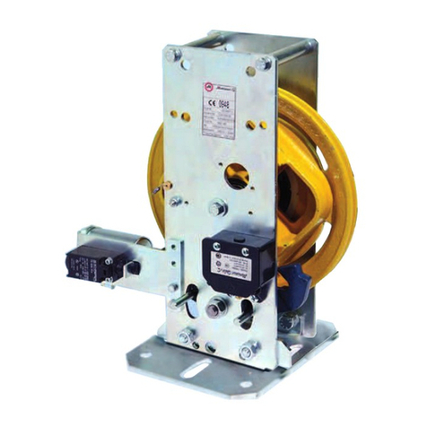
Montanari NOR Quick start guide

www.montanarigiulio.com
REV: 06_11_2022
MANUAL
NOR - RG200
INSTALLATION, USE AND MAINTENANCE
SPEED GOVERNORS

2
REV: 06_11_2022
www.montanarigiulio.com
CHOOSE MONTANARIAPP! Available mobile and desktop.
A unique container of all documentation available for gearboxes, gearless, speed
governors and safety gears.
You may check your supply, configure the inverter, download manuals, tech
reports, certificates and much more.
Search for Montanari Giulio mobile App, available on Google Play and App store.
SCAN THE QR TO DOWNLOAD
ANDROID APP
SCAN THE QR TO DOWNLOAD
iOS APP
SCAN THE QR FOR THE DESKTOP
APP

3
www.montanarigiulio.com
ENGLISH
SPEED GOVERNORS: NOR - RG
REV: 06_11_2022
Thank you for choosing a Montanari product.
Since 1970, Montanari Group has been focused on
providing its customers with the best traction machines and
components for lifts and escalators.
We are proud to have you as a customer and user of the
Montanari traction machines, and we are confident that we
can work together for a long time.
Massimo Montanari
CEO of Montanari Group

4
REV: 06_11_2022
www.montanarigiulio.com
CONTENTS
1. GENERAL INFORMATION............................................................... 7
1.1 Introduction ...........................................................................................7
1.2 Copyright...............................................................................................7
2. SAFETY ........................................................................................... 8
2.1 Intended use ..........................................................................................8
2.2 User’s obligations...................................................................................8
2.3 Proper disposal......................................................................................9
2.4 Safety of operators..............................................................................10
3. IDENTIFICATION AND DATA......................................................... 10
3.1 Identification plate ..............................................................................10
3.2 Legal references...................................................................................10
3.3 Technical data ......................................................................................11
3.4 Pull force .............................................................................................11
4. TRANSPORT AND STORAGE ........................................................ 14
4.1 Handling...............................................................................................14
4.2 Storage.................................................................................................14
5. DESCRIPTION AND OPERATION .................................................. 15
5.1 General description .............................................................................15
5.2 Components ........................................................................................15
5.3 Mechanical intervention.......................................................................18
5.4 Electrical intervention..........................................................................18
6. INSTALLATION AND FIXING ......................................................... 18
6.1 Installation surface - Fixing..................................................................18
6.2 Installation of ropes .............................................................................20
6.3 Electrical installation - Excess speed contact......................................21
7. INSTALLATION OF SPEED GOVERNORS WITH OPTIONAL ACCESSORIES21
7.1 Electrical installation of the REMOTE CONTROL............................ 21
7.2 Protection cover ..................................................................................22
8. OPERATING TEST.......................................................................... 23
8.1 Static test.............................................................................................23
8.2 Dynamic test ........................................................................................24
9. TROUBLESHOOTING, MAINTENANCE AND REPAIR.................... 25
9.1 General information.............................................................................25
9.2 Problems, causes and solutions ..........................................................25
9.3 Checks..................................................................................................25
9.4 Repairs .................................................................................................26
10. SPEED GOVERNOR CERTIFICATE ................................................. 26

5
www.montanarigiulio.com
ENGLISH
SPEED GOVERNORS: NOR - RG
REV: 06_11_2022

6
REV: 06_11_2022
www.montanarigiulio.com
!
The speed governor is pre-adjusted and calibrated at the factory.
No intervention is allowed without authorization by Montanari Giulio & C.
Srl.
TIP
!
!
It indicates that safety measures must
be taken to avoid electric shock.
It indicates that safety measures must
be taken to prevent personal injury.
It indicates that safety measures
must be taken to prevent damage to
components.
It indicates that safety measures must
be taken to prevent burns due to
contact with hot/ overheated surface.
It indicates useful information before
and during the installation step.
It refers to specific parts of the
manual.
It refers to the proper product
disposal.
REV. DATE DESCRIPTION EDITED BY VERIFIED BY APPROVED BY
1 30/01/2019 FIRST REDACTION Marketing Dept Ufficio Tecnico
Stefano Bertoni STEFANO BERTONI (DTE)
2 22/07/2019 SECOND REDACTION Marketing Dept Ufficio Tecnico
Stefano Bertoni STEFANO BERTONI (DTE)
3 23/03/2021 UPDATE Marketing Dept Ufficio Tecnico
Stefano Bertoni STEFANO BERTONI (DTE)
4 22/03/2022 UPDATE Marketing Dept Ufficio Tecnico
Stefano Bertoni STEFANO BERTONI (DTE)
5 08/04/2022 UPDATE Marketing Dept Ufficio Tecnico
Stefano Bertoni STEFANO BERTONI (DTE)
6 04/11/2022 UPDATE Marketing Dept Ufficio Tecnico
Stefano Bertoni STEFANO BERTONI (DTE)

7
www.montanarigiulio.com
ENGLISH
SPEED GOVERNORS: NOR - RG
REV: 06_11_2022
1. GENERAL INFORMATION
1.1 Introduction
The speed governors by Montanari Giulio & C. are designed and tested to
ensure proper operation.
These operating instructions are an integral part of the speed governors and
must always be kept within easy reach for consultation.
All persons involved in the installation, operation, maintenance and repair of the
unit must read and understand the instructions.
No liability is accepted for damage, breakage or accident caused by failure to
follow the instructions provided in this manual.
The NOR - RG - RH speed governors described herein has been designed
and manufactured in accordance with the recognized safety standards and the
state of the art technical development applied at the time of printing.
Speed governors are lead sealed. A special anti-tamper paint was applied
on the screws, because they cannot be removed.
The breakage of lead seal and any tampering involves the cancellation of
the manufacturer’s warranty.
To make technical improvements, Montanari reserves the right, if deemed nec-
essary, to modify the units and accessories, preserving their essential character-
istics and improving efficiency and safety.
1.2 Copyright
All rights to these operating instructions belong to Montanari Giulio & C. S.r.l.
The information in this manual may not be reproduced or used in an unauthor-
ized manner or made available to third parties without prior permission.
If you have any questions, please contact:
MONTANARI GROUP
HEADQUARTER - MONTANARI GIULIO & C. Srl
Via Bulgaria 39 - 41122 - Modena - Italia
Tel: +39 059 453611 - Fax: +39 059 315890
www.montanarigiulio.com
!

8
REV: 06_11_2022
www.montanarigiulio.com
2. SAFETY
2.1 Intended use
The speed governor is produced in compliance with the state of the art for safe
and reliable use. It is forbidden to tamper with devices or functions designed to
prevent accidental contact.
It is prohibited to use the safety limiter for activities other than the one for
which it was produced and the conditions set out in the supply contract.
!
No liability is accepted for any malfunction due to installation not confor-
ming to specifications, except in cases approved by Montanari Giulio & C.
2.2 User’s obligations
The responsibility for instructions lies with the company in charge of the work.
The operator must ensure that all persons involved in installation, operation,
maintenance and repair have read and understood the supplied operating in-
structions and have adapted to them in order to:
• Avoid damage to property or persons.
• Ensure safe and reliable operation of the unit.
• Avoid breakage and environmental damage due to misuse.
Immediate voidance of the guarantee in case of:
• Use of components other than those installed.
• Any modification to the governor.
• Destruction of the lead seal, removal of commissioning adhesive labels or of
the anti-tampering paint.
• Wrong maintenance or wrong inspection checks.
• Use of accessories and / or spare parts which are unsuitable or non authori-
zed/genuine by Montanari.
!
Before installing on the system check that:
• Data plate details and lift speed correspond to those of the system.
• The diameter of the rope is suitable to the governor/tension device pulley.
IMPORTANT:
Safety devices require a special attention:
• Test their operation immediately after installation.
• It is forbidden to dismantle a safety device during maintenance or repair if
the intervention involves parts that may affect the settings set at the factory
(lead sealing, seals, etc., see also warranty voidance).
! !
See detail in paragraph 2.2

9
www.montanarigiulio.com
ENGLISH
SPEED GOVERNORS: NOR - RG
REV: 06_11_2022
In particular:
• During transport, assembly, installation, operation, maintenance and di-
smantling of the unit, the relevant environmental and safety standards must
always be complied with.
• The unit must only be used, maintained and repaired by authorized, properly
trained and qualified personnel.
• The governor must not be cleaned using high-pressure cleaning equipment.
• All work must be carried out with care and with due attention to safety.
• Any work on the unit should only be carried out when it is not in operation.
• No welding must be carried out on the unit.
• Do not use the unit as a grounding point for welding operations.
• If the unit is intended for installation in plant or machinery, the manufacturer
of such plant or machinery must ensure that the standards, indications and
descriptions contained in these operating instructions are incorporated into
its own instructions.
• The information on the warning or identification plates must be complied
with. These plates must be kept clean and legible at all times. Missing plates
must be replaced.
All spare parts can be obtained from Montanari Giulio & C.
PERSONAL PROTECTIVE EQUIPMENT TO BE USED:
• Protection gloves against mechanical injuries
• Safety shoes
2.3 Proper disposal
Respect the environment and dispose of the product according to the
regulations in force in the country of installation.
WASTE DISPOSAL AND PRODUCT DISMANTLING
The product consists mainly of steel, cast iron, iron and other materials such as
rubber, plastic, etc., which are not particularly hazardous.
For this reason, disposal does not require any special safety procedures other
than the conventional ones adopted for this type of waste.
Dispose of the product in compliance with the Environmental and Hygiene Re-
gulations in force in the country it is installed in.
Contact a specialised company for disposal.
Please note that the classification of the waste is responsibility of the waste
producer himself; for disposal comply with the code 16.02.14 “Discarded equip-
ment, other than those mentioned in 16.02.09 to 16.02.13.”

10
REV: 06_11_2022
www.montanarigiulio.com
3. IDENTIFICATION AND DATA
3.1 Identification plate
The data shown on the plate are indicated in FIG. 1.
Manufacturer
Manufacturer’s
address
Item code
Serial no. /year of production
Fig. 1
Order confirmation
Model
Max. tripping speed
Identification code of the body appointed for
production supervision carrying out the inspection
Type certificate
Order number Certification body
QR code to access all
the documentation.
Tab. 1
N NORM DESCRIPTION
1 UNI 10147 Maintenance: Terminology.
2 EN 81- 20 Safety rules for the construction and installation of lifts for the transport of per-
sons and goods.
3 EN 81 - 50 Safety rules for the construction and installation of lifts - Examinations and tests.
4 EN 81 - 21 Safety rules for the construction and installation of lifts for the transport of
persons and goods in existing building.
3.2 Legal references
2.4 Safety of operators
For the safety of operators and other people, the following procedures are compulsory:
• Use the safety devices preventing fall (platform and or harness).
• Cover any holes on the ground.
• Protect installation tools or objects from accidental fall.
• Use fences to protect the openings of the lift shaft and position warning signs when
working on the same.
! !

11
www.montanarigiulio.com
ENGLISH
SPEED GOVERNORS: NOR - RG
REV: 06_11_2022
Model Dimension Nominal
Speed ø Ropes Intervention Testing
Groove
[m/s] [mm]
RIF. TAB min max
NOR 170 Fig. 2 0,30 1,50 6 - 8 One Way - Bidirectional Yes
RG 200 131 - 139 Fig. 3 - 4 0,15 0,30 6 - 6,5 One Way - Bidirectional No
3.3 Technical data
The following drawings show the overall dimensions of: NOR - RG200.
For versions with optional, see the specific sections.
Tab. 2
Tab. 3
Force produced by the tensio-
ning mass acting on the axis of
the pull pulley [N]
Pull force acting on the safety gear lever:
DOWNWARDS [N] UPWARDS [N] INTERVENTION
288 349,88 --- ONE-WAY
825 862,27 361,30 TWO-WAY
3.4 Pull force

12
REV: 06_11_2022
www.montanarigiulio.com
Fig. 2
NOR - Tab 170
INSTALLATION
HANDSIDE DX
INSTALLATION
HANDSIDE DX
STANDARD BASE
Fig. 3
RG200 - Tab 131

13
www.montanarigiulio.com
ENGLISH
SPEED GOVERNORS: NOR - RG
REV: 06_11_2022
INSTALLATION
HANDSIDE DX
NARROW BASE
RG200 - Tab 139
Fig. 4

14
REV: 06_11_2022
www.montanarigiulio.com
Keep dry Handle with care
Upper side Do not use hooks
Fragile Center of gravity
Keep away from heat
sources
Attachment point
For rising, only use pins/spa-
cers shown in the figure.
Never lubricate or grease me-
chanical components!
Deposits of dirt and dust can
compromise the correct ope-
ration.
! !
4. TRANSPORT AND STORAGE
4.1 Handling
Different types of packaging can be used, depending on the size and means
of transport. Unless otherwise specified, the packaging complies with the HPE
guidelines.
It is recommended to verify also the condition of the goods upon receipt. In case
of damages do not proceed with installation except for Montanari Giulio & C.
authorization.
Comply with the symbols on the packaging to prevent damage to property or
personal injury. Here are the meanings of the symbols that may appear on the
packaging.
4.2 Storage
The unit must be kept in a closed and dry environment.
!
Supplies for special environmental conditions during transport (e.g.
by ship) and storage (climate, temperature, etc.) must be contractually
agreed.
!
Fig. 5

15
www.montanarigiulio.com
ENGLISH
SPEED GOVERNORS: NOR - RG
REV: 06_11_2022
5. DESCRIPTION AND OPERATION
5.1 General description
The speed governor is a safety device that trips when the car reaches the inter-
vention speed at which it is calibrated.
Governor:
• One-way - it operates the safety gear lever in its downwards movement.
• Two-way - it operates in both travel direction.
Thespeed governoris designedfor detectingthe excessspeed andto intervene
both mechanically and electrically as below described:
• the mechanical part activates the safety gear
• the electric part stops the lift drive
Note: A tension device is required to tension the speed governor rope
(see for example TAB163.1 and TEV on product general catalogue of
Montanari Giulio & C.)
5.2 Components
The following figures show the parts forming the NOR - RG - RH governor in
standard version.
!
See detail in paragraph 5.4
Pulley
Fig. 6
3. Lever
1. Wheel
2. Pulley Square
4. Spring 5. Locking Tooth
Arrow showing the
engagement direction
of the safety gear
NOR - Tab 170
6. Rope Guard

16
REV: 06_11_2022
www.montanarigiulio.com
Label
Fig. 7
7. Safety Contact
Fixing base
Test groove
Fig. 8

17
www.montanarigiulio.com
ENGLISH
SPEED GOVERNORS: NOR - RG
REV: 06_11_2022
Pulley
Fig.9
2. Lever
Label
Fig. 10
1. Wheel
3. Spring
4. Locking Tooth
1. Spacer pin
Fixing base
RG200 - Tab 170
Arrow showing the
engagement direction
of the safety gear
2. Remote control

18
REV: 06_11_2022
www.montanarigiulio.com
5.3 Mechanical intervention
Fig. 6 - 7 - 8: The wheel (1) rotates on the pulley square (2) and pulls the lever (3)
downwards.
In this way, the spring (4) prevents the lever from opening until the intervention
speed is reached.
The lever (3) rotates and engages one of the locking teeth (5).
The pulley does not rotate anymore and causes the mechanical intervention of
the safety gear.
5.4 Electrical intervention
Fig. 6 - 7 - 8: The wheel (1) rotates on the pulley square (2) and pulls the lever (3)
downwards. In this way, the spring (4) prevents the lever from opening until the
intervention speed is reached.
The pin rises, activates the safety contact (7) and opens the safety chain.
6. INSTALLATION AND FIXING
The speed governor must be installed in a building or in a closed travel com-
partment.
Do not use in an explosive atmosphere. Room temperature must range between
0°C e +40°C (for operating temperatures below or above, contact the Montanari
technical office unless expressly agreed/authorised).
Assembly and installation must be carried out with great care by qualified and
trained personnel. The manufacturer cannot be held responsible for damage
caused by incorrect assembly or incorrect installation. Before starting work,
make sure that adequate lifting and handling equipment is available. All fixing
points specified by the manufacturer must be used.
! !
Check the rotating direction: the speed governor can be on car side or coun-
terweight side. The arrow on the governor (Fig. 6) must be in the engagement
direction of the safety gear.
6.1 Installation surface - Fixing
The speed governor is suitable for being used both with room or without room.
The installation surface must be uniform, level and horizontal. The levelling to-
lerance is 0.2 mm. The installation surface must be rigid and robust enough to
withstand the forces involved.
Pay special attention to prevent shocks to the governor.
Place the unit on the installation surface and secure it. Do not force or hit the
fixings to position them; this could damage the governor.

19
www.montanarigiulio.com
ENGLISH
SPEED GOVERNORS: NOR - RG
REV: 06_11_2022
Fig. 11
! !
FIXING: The speed governor must be fixed checking its vertical direction with
a bubble level or a lead wire.
! !
MAX. ALLOWED SLOPING: The speed governor must be installed so that the
rope runs parallel in the pulley groove. The rope max. recommended sloping (A)
is ± 0.50°.
Fig. 10
Fig. 12
A

20
REV: 06_11_2022
www.montanarigiulio.com
6.2 Installation of ropes
The speed governor only works in a perfect way if rope and tension device are
correctly installed.
1. Gather the rope close to the governor and thread one head through the
governor towards the safety gear levers.
2. Connect the first rope attachment to the same rope and secure it to the
safety gear lever.
3. Install the tension device following its installation instructions.
4. Connect the second head of the rope - passing through the tension device
- to the rope attachment and then to the safety gear lever.
Fig. 13
SPEED GOVERNOR
Rope
Rope Attachment
Tension device
Support
Safety gear levers
This manual suits for next models
1
Table of contents
Other Montanari Industrial Equipment manuals

Montanari
Montanari MGX75 User manual

Montanari
Montanari RQ 200 User manual

Montanari
Montanari M73ES Quick start guide

Montanari
Montanari M93ES Quick start guide

Montanari
Montanari MGV34 Series Parts list manual

Montanari
Montanari MGX90 ELEVO User guide

Montanari
Montanari MGX80 Quick start guide

Montanari
Montanari M50P Quick start guide

Montanari
Montanari MGS19 Quick start guide