CONTENTS
Safe Operation Practices
.....
......
...
......
2
Index and
Know
Your
MOPED
...
.
...
..
......
. 3 Exploded View for Fork and Handle Bar
.......
18
Parts
List
for
Fork and Handle Bar
.....
.
.....
.19
Cons
umer
Information
....
.
..
.......
.....
...
4 Exploded View
for
Main Frame
.....
...
..
...
..
20
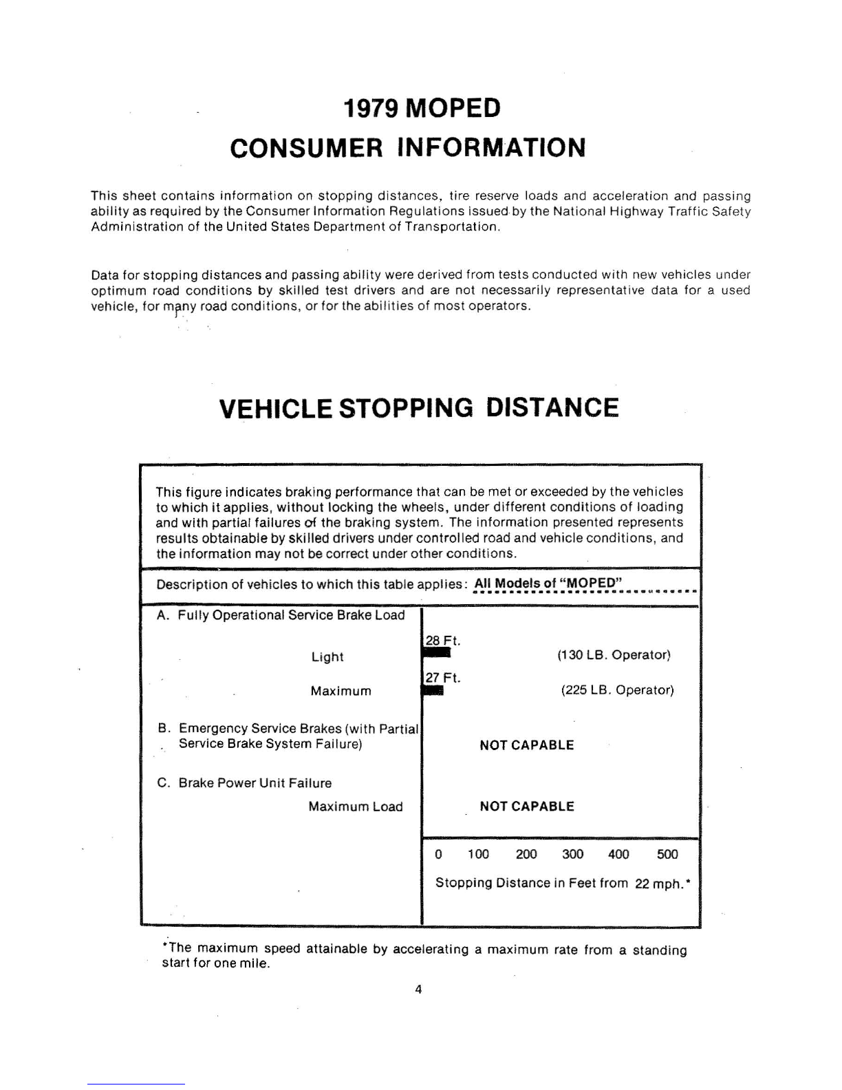
Tire Reserve Load
..........................
5 Parts
List
fo
r Main Frame
................
21, 22
Identification
..........
. .
................
..
6 Exploded View
for
Torque Converter
..........
23
Assembly
Instructions
..
.
......
.
.........
.
..
6
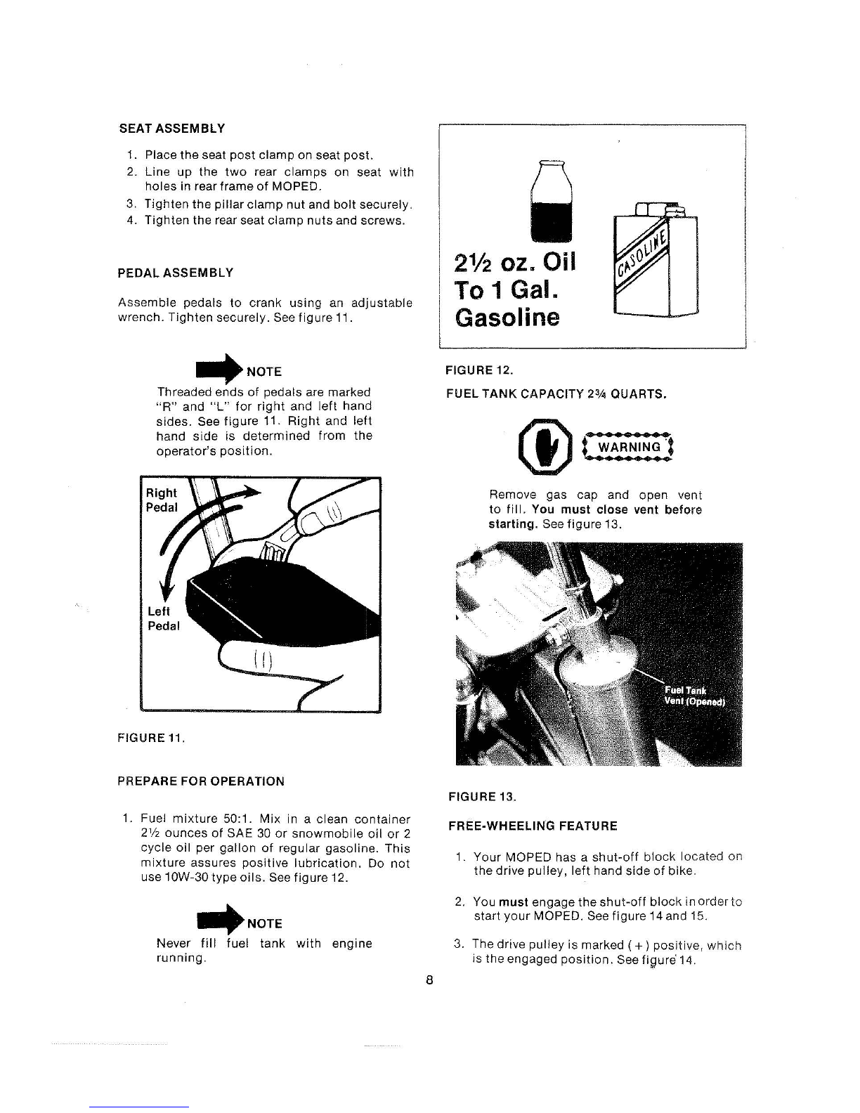
Prepare
for
Operation
......
.
................
8
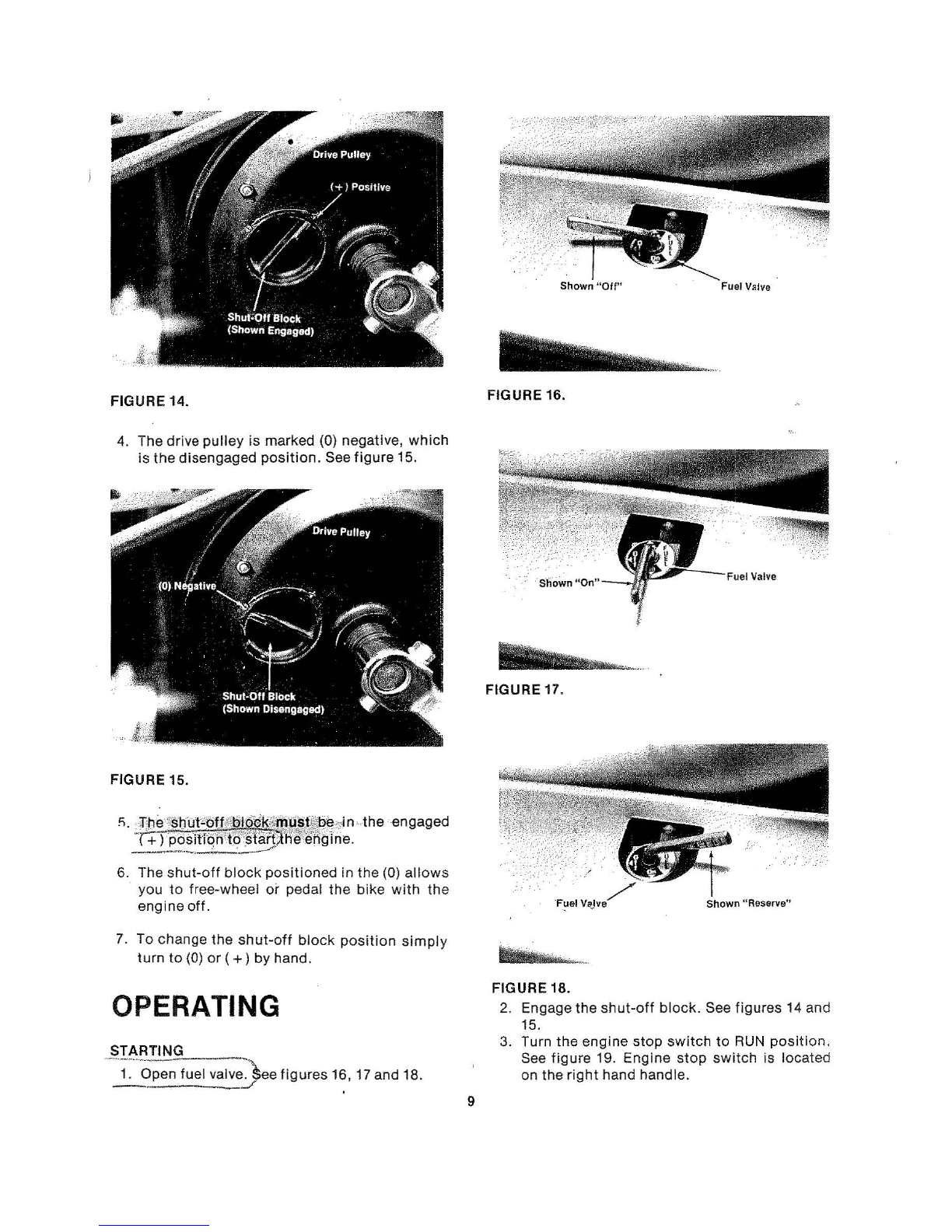
Operating . . . . . . . . . . . . . . . . . . . . . . . . . . . . . . . . . 9
Maintenance . .
....
.
....
.
....
..
...
. .
..
..
...
10
Exploded View and Parts
List
for
Front Wheel 24
Exploded View and Parts
List
for
Rear Wheel .
..
25
E
xploded
View and Parts
List
for
Controls
.....
26
E
xploded
View and Parts
List
for
Engine
....
27-31
Adjustments
....
..
..
.
...........
.........
.13 Parts Ordering Procedure
...........
BackCover
Wiring
Diagram
...
.
....
. .
....
..
.........
..
.
17
KNOW YOUR MOPED
FIGU
RE
1. RIGHT
HAND
VI
EW FIGURE 2. LEFT
HA
ND VIEW
1. Brake/Tail
Light
1.
Amber
Reflector (Front)
2. Seat 2. Headlig
ht
3. Breather Cap
3.
Speedometer
4. Fuel Tank and Cap 4. Rear View
Mirror
5. Choke Lever 5. Starter Lever
6.
Throttl
e
Twist
Grip 6. Brake Lever (Rear)
!'
7.
Start/Stop
Switch
7.
Seat
Adjusti
ng
Bolt
8. Brake Lever
(Front)
8.
Red Reflector (Rear)
9.
Front
Internal Drum Brake 9. Chain
Adjuster
10. Front Fork Extension 10. Rear Wheel
11.
Right
Hand Pedal 11.
Kickstand
12. Pedal Chain 12.
Muffler
13. Rear Internal Drum Brake 13.
Front
Wheel
14
. Rear
Swing
Arm Shock
3