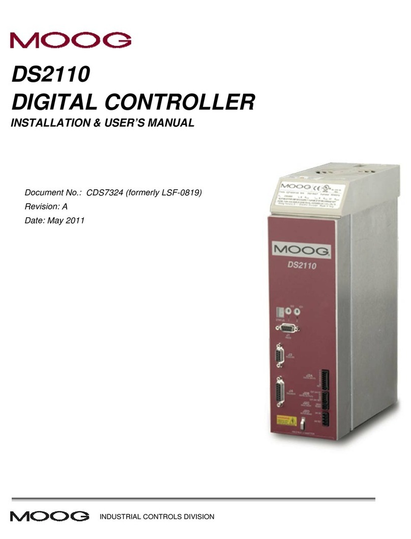
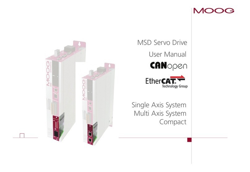
Moog MDS Servo Drive User manual

moog
Single-Axis ServoDrive - Compact
Single-Axis ServoDrive - Standard
Multi-Axis ServoDrive - System
MSDServoDrive
User Manual
PROFIBUS / PROFINET

2
MSD Servo Drive User Manual PROFIBUS/PROFINET
ID no.: CA65645-001 Date: 01/2015
moog
This document details the functionality of the following devices:
Single-Axis ServoDrive - Compact
Single-Axis ServoDrive - Standard
Multi-Axis ServoDrive - System
PROFIBUS/PROFINET User Manual for MSDServoDrive
ID no.: CA65645-001, Rev. 3.0
Date: 01/2015
Subject to technical change without notice.
The German version is the original of this Operation Manual.
Subject to technical change without notice.
The contents of our documentation have been compiled with greatest care and in
compliance with our present status of information.
Nevertheless we would like to point out that this document cannot always be updated
parallel to the technical further development of our products.
Information and specifications may be changed at any time. For information on the
latest version please refer to drives-support@moog.com.

3
MSD Servo Drive User Manual PROFIBUS/PROFINET
ID no.: CA65645-001 Date: 01/2015
moog
How to use this document
Dear user,
This manual is intended for use by project engineers, commissioning engineers and
programmers of drives and automation solutions involving the PROFIBUS/PROFINET
fieldbus. It is assumed that you are already familiar with at least one of these fieldbuses
on the basis of appropriate training and reading of the relevant literature. We assume
that your drive has already been commissioned – if not, please first refer to the user
manual. 11 General introduction
44 Acyclic data transfer
55 Operation modes
66 Homing
Appendix: Glossary, Index
33 Cyclic data transfer
22 Commissioning
77 Examples of commissioning
88 PROFIBUS/PROFINET parameters

MSD Servo Drive User Manual PROFIBUS/PROFINET
ID no.: CA65645-001 Date: 01/2015
moog 4
Pictograms
!Attention! Misoperation may result in damage to the drive or malfunctions.
Danger from electrical tension! Improper behaviour may endanger human life.
Danger from rotating parts! Drive may start up automatically.
Note: Useful information

5
MSD Servo Drive User Manual PROFIBUS/PROFINET
ID no.: CA65645-001 Date: 01/2015
moog
Table of contents
1 General .................................................................................... 7
1.1 Measures for your safety.....................................................................................7
1.2 Introduction........................................................................................................7
1.3 System requirements...........................................................................................7
1.4 Further documentation .......................................................................................7
1.5 Helpline/Support & Service..................................................................................8
2 Commissioning......................................................................... 9
2.1 PROFIBUS ...........................................................................................................9
2.1.1 Connections and user controls.............................................................9
2.1.2 Pin assignment of the D-Sub socket .....................................................9
2.1.3 Specification of the PROFIBUS cable ....................................................10
2.1.4 Bus termination ...................................................................................10
2.1.5 PROFIBUS address setting ....................................................................11
2.1.6 PROFIBUS option card displays.............................................................11
2.1.7 GSD file (PROFIBUS) .............................................................................12
2.2 PROFINET............................................................................................................13
2.2.1 Connections ........................................................................................13
2.2.2 Pin assignment of the RJ45 socket .......................................................13
2.2.3 Specification of the PROFINET cable ....................................................14
2.2.4 Meanings of LEDs ................................................................................14
2.2.5 PROFINET option card displays.............................................................15
2.2.6 GSDML file (PROFINET) ........................................................................15
3 Cyclic data transfer ................................................................. 17
3.1 Parameter process data objects (PPOs) ................................................................17
3.1.1 Standard "PROFIdrive" telegrams.........................................................17
3.1.2 User-specific PPOs................................................................................19
3.1.3 Parameter channel PKW ......................................................................23
3.2 Monitoring..........................................................................................................24
3.2.1 Watchdog............................................................................................24
3.2.2 Sign of Life...........................................................................................24
4 Acyclic data transfer ............................................................... 27
4.1 PROFIBUS parameter access ................................................................................27
4.2 PROFINET parameter access ................................................................................29
4.3 "Base Mode Parameter Access" data format.......................................................29
4.4 Examples of request and response telegrams ......................................................32
5 Profidrive operation modes ..................................................... 35
5.1 Profinet operation modes....................................................................................35
5.1.1 Speed control circuit and associated control parameters......................36
5.2 Drive state machine.............................................................................................37
5.3 Jog mode............................................................................................................38
5.3.1 Jog mode manufacturer-specific ..........................................................38
5.3.2 Jog mode conforming to profile...........................................................38
5.3.3 Jog mode reference parameters ..........................................................39
5.4 Speed control (application class 1).......................................................................39
5.4.1 Master control word ............................................................................40
5.4.2 Drive status word.................................................................................41
5.5 Position control (application class 3)....................................................................42
5.5.1 Position control circuit and associated control parameters ...................44
6
MSD Servo Drive User Manual PROFIBUS/PROFINET
ID no.: CA65645-001 Date: 01/2015
moog
6 Homing .................................................................................. 49
6.1 Drive-controlled homing .....................................................................................49
6.2 Homing velocity ..................................................................................................49
6.3 Homing acceleration ...........................................................................................49
6.4 Zero point offset .................................................................................................49
6.5 Homing method..................................................................................................49
6.6 Reference cam, limit switch.................................................................................51
7 Examples of commissioning with manufacturer-specific
telegrams ............................................................................... 53
7.1 Position control with PPO 5.................................................................................53
7.2 Controlled homing ..............................................................................................54
7.3 Conversion of reference and actual values via the factor group parameters .......54
7.4 Examples for setting the user factor group..........................................................56
7.5 Speed control with PPO 2 ...................................................................................56
7.5.1 Speed input .........................................................................................57
7.6 Mappable parameters .........................................................................................58
8 PROFIBUS/PROFINET parameters ............................................. 59
9 Appendix................................................................................ 61
9.1 Glossary..............................................................................................................61
9.2 Technical data .....................................................................................................61

7
General
MSD Servo Drive User Manual PROFIBUS/PROFINET
ID no.: CA65645-001 Date: 01/2015
moog
1 General
1.1 Measures for your safety
Servo drives of the MSDServoDrive family are quick and easy to handle. For your
own safety and for the safe functioning of your device, please be sure to observe the
following points:
Read the Operation Manual first!
1.
xFollow the safety instructions!
Electric drives are dangerous:
xElectrical voltages > 230 V/460 V:
Dangerously high voltages may still be present 10minutes after the power is
cut. So check that the power has been cut!
xRotating parts
xHot surfaces
Your qualification:
xIn order to prevent personal injury and damage to property, only
personnel with electrical engineering qualifications may work on the device.
xKnowledge of the national accident prevention regulations (such as VBG4
inGermany)
xKnowledge of layout and interconnection of fieldbuses
U
V
N
L+
RB
L-
L3
L2
L1
U
V
N
L+
RB
L-
L3
L2
L1
During installation observe the following instructions:
xAlways comply with the connection conditions and technical specifications.
xElectrical installation standards,such as cable cross-section, shielding, etc.
xDo not touch electronic components and contacts (electrostatic discharge
may destroy components).
1.2 Introduction
PROFIBUS based on standards and its modular interfaces. Thanks to its use of a
single standardised, non-application-dependent communication protocol, PROFIBUS
provides solutions for the process industry as well as in a wide range of motion control
applications.
PROFINET permits enhanced system-wide connectivity, adding to tried and
proven PROFIBUS technology for applications specifying fast data communication
in combination with industrial IT functionality. Thanks to its Ethernet-based
communication, PROFINET meets a wide range of requirements, from data-intensive
parameter assignments to synchronised data transfer. Communication for all applications
is routed through just one cable. Whether for a simple control task or for highly
dynamic motion control of drive axes. TCP/IP-based communication in the PROFINET
network enabling extensive system diagnostics in a control station or over the Internet is
implemented in parallel with real-time communication.
1.3 System requirements
− PROFIBUS/PROFINET configuration program installed.
− PROFIBUS/PROFINET device description file for corresponding field device
installed.
1.4 Further documentation
yInstructions for commissioning the drive device
yPROFIBUS user organisation "PROFIdrive - PROFIDrive Technology for PROFIBUS
and PROFINET" Version 4.1, May 2006, Order no. 3.172
yPROFIBUS User Organisation: "Profile Guidelines Part 1: Identification &
Maintenance Functions, 1.2, Oct 2009, Order No. 3.502"

8
General
MSD Servo Drive User Manual PROFIBUS/PROFINET
ID no.: CA65645-001 Date: 01/2015
moog
1.5 Helpline/Support & Service
Our Helpline can provide you with fast, targeted assistance if you have any technical
queries relating to project planning or commissioning of the drive unit. To that end,
please collect the following information prior to making contact:
1. Type designation, serial number and software version of the devices (see
Software rating plate)
2. Moog
DriveADministrAtor
version in use (menu ►Help ►Information...
►Version)
3. Displayed error code version (on 7-segment display or Moog
DriveADministrAtor
)
4. Description of the error symptoms, how it occurred and relevant circumstances
5. Save device settings to file in Moog
DriveADministrAtor
6. Name of company and contact, telephone number and e-mail address
If you have any technical questions concerning project planning or commissioning of the
servo drive, please feel free to contact our helpline.
yHelpline - Please contact us:
Moog GmbH
Hanns-Klemm-Straße 28
D-71034 Böblingen
Phone: +49 7031 622 0
Telefax: +49 7031 622 100
E-Mail: d[email protected]m
If you need further assistance, our specialists at the Moog Service Center will be
happy to help.
yService - Please contact us:
Phone: +49 7031 622 0
E-Mail: info.germany@moog.com

9
Commissioning
MSD Servo Drive User Manual PROFIBUS/PROFINET
ID no.: CA65645-001 Date: 01/2015
moog
2 Commissioning
2.1 PROFIBUS
Note:
For technical data and information on topologies and maximum cable lengths see
chapter 9.2.
2.1.1 Connections and user controls
The connections and user controls of the PROFIBUS interface are shown in table 2.1.
LEDs H1, H2, H3 act as status indicators. The rotary coding switches S1 and S2
(MSDServoDrive only) can be used to set the PROFIBUS address of the drive. The
PROFIBUS cable is connected to the D-Sub socket X14.
Front panel No. Comments
MSDServoDrive Single-Axis Compact H1 Status indicator LED (yellow)
H2 Status indicator LED (red)
H3 Status indicator LED (green)
S11)
Rotary coding switch to set the
PROFIBUS address for the drive =
0x(S2)(S1)
S21)
Rotary coding switch to set the
PROFIBUS address for the drive =
0x(S2)(S1)
X14 PROFIBUS cable connection
1) MSDServoDrive only
Table 2.1 PROFIBUS option card
2.1.2 Pin assignment of the D-Sub socket
PROFIBUS is connected via a nine-pin sub-D plug connector. The pin assignment is
shown in the diagram below and described in the following table.
Figure 2.1
X14
12345
6789
RxD
TxD-P DGND
RxD
TxD-N
VP
5 Volt
Pin assignment of D-SUB connector
Pin RS-485 Signal Description
1SHIELD Earthed shield
2RP Reserved for power supply via bus
3B/B’ (red) RxD / TxD-P Send and receive data (+)
4CNTR-P Control signal for repeater (+)
5C/C’ DGND Data reference potential and power
supply to terminating resistor (-)
6VP Power supply for terminating resistor (+)
7RP Reserved for power supply via bus
8A/A’
(green) RxD / TxD-N Send and receive data (-)
9CNTR-N Control signal for repeater (-)
Table 2.2 Description of pin assignment
The pin assignments highlighted in table 2.2 are necessary from the user’s viewpoint.
The control signals used for the repeaters are optional, and the power supply for the
terminating resistors is provided by the device.

10
Commissioning
MSD Servo Drive User Manual PROFIBUS/PROFINET
ID no.: CA65645-001 Date: 01/2015
moog
2.1.3 Specification of the PROFIBUS cable
For the wiring Moog recommends using the following hardware:
PROFIBUS D-Sub bus termination plug
Siemens order number 6XV1 830-0EH10
Siemens article description PB FC EIA485 PLUG 180, AXIAL CABLE OUTLET
Table 2.3 Recommended PROFIBUS D-Sub bus termination plug
PROFIBUS cable
Siemens order number 6GK1 500-0FC10
Siemens article description SIMATIC NET, PB FC STANDARD CABLE GP, 2-WIRE, SHIELDED
Table 2.4 Recommended PROFIBUS cable
2.1.4 Bus termination
If the MSDServoDrive is initially at the end of the bus system, a plug with an integral
terminating resistor Rt should be used. In addition to the cable terminating resistor in
accordance with the EIA485 standard, a pull-down resistor Rd against the data reference
potential DGND and a pull-up resistor Ru against VP are provided. This ensures a defined
no-load potential of 1.1 Volt between pins 3 and 8. In a made-up PROFIBUS cable these
resistors are all incorporated as standard in the PROFIBUS plug and the terminating
resistor can be activated using a switch on the PROFIBUS plug. The following figure
shows a Sub-D 9-pin plug bus termination.
Figure 2.2
plug PROFIBUScabel
Unit
Vp = 5 Volt (6)
RxD TxD-P (3)
RxD TxD-N (8)
GND (6)
Ru = 390 Ohm
Rt = 220 Ohm
Rd = 390 Ohm
B (red)
A (green)
Sub-D 9-pin plug bus termination

11
Commissioning
MSD Servo Drive User Manual PROFIBUS/PROFINET
ID no.: CA65645-001 Date: 01/2015
moog
2.1.5 PROFIBUS address setting
MSDServoDrive
Select the mode of addressing:
1. Coding switches S1 and S2
By way of the two coding switches a hexadecimal address between 0 and 125
is set.
S
2
S
1
4
5
6
7
8
9
A
B
C
D
E
F
0
2
3
1
4
5
6
7
8
9
A
B
C
D
E
F
0
1
3
2
Figure 2.3 Coding switches for PROFIBUS address
2. Bus address parameter P 0918
By way of bus address parameter P 0918-COM_DP_Adress a valid decimal
address between 0 and 125 is set.
A setting via this parameter is only valid if an address above 125 is set via the
coding switches (e.g. 0xFF, i.e. S1=S2=F).
3. Setting via device keypad
A valid hexadecimal address between 0 and 125 is set using the device
keypad on the submenu "Fb". The preset value is written to bus address
parameter P0918. Instructions for use of the device keypad are given in the
MSDServoDrive Operation Manual.
A setting via the device keypad is only valid if an address above 125 is set via
the coding switches (e.g. 0xFF, i.e. S1=S2=F).
Note:
All setting modes require the device to be restarted in order to activate the new
address.
Single-Axis Compact
Select the mode of addressing:
4. Bus address parameter P 0918
By way of bus address parameter P 0918-COM_DP_Adress a valid decimal
address between 0 and 125 is set.
5. Setting via device keypad
A valid hexadecimal address between 0 and 125 is set using the device keypad
on the submenu "Fb". The preset value is written to bus address parameter
P 0918. Instructions for use of the device keypad are given in the Single-
AxisCompact Operation Manual.
Note:
All setting modes require the device to be restarted in order to activate the new
address.
The following functions and displays are available:
yDisplay of device state
The device state is displayed when the control supply is switched on. If no input
is made via the keypad for 60seconds, the display switches back to the device
state.
yDisplay of device error state
If a device error occurs the display immediately switches to show the error code.
yParameter setting (display "PA")
Reset device parameters to their factory setting
yEthernet IP address setting (display "IP")
Set Ethernet IP address and subnet mask
yFieldbus settings (display "Fb")
Set fieldbus address for example
2.1.6 PROFIBUS option card displays
Three LEDs are mounted on the PROFIBUS option card indicating the current operating
status of the module. The following tables set out the operating states of the PROFIBUS
option card based on the various illumination sequences.

12
Commissioning
MSD Servo Drive User Manual PROFIBUS/PROFINET
ID no.: CA65645-001 Date: 01/2015
moog
LED 3, green LED 2, red Status
Reset (after power on)
ASIC RAM test and initialisation
End of ASIC RAM test and initialisation
Table 2.5 Self-test during diagnostics
LED 3, green LED 2, red Status
Seeking baud rate after power on without bus
connection
Seeking baud rate after bus connection has already
been made
Waiting for parameterisation data
Communication: Data exchange without acyclic
master class 2 connection. Yellow LED lit.
Communication: Data exchange "clear state"
Incorrect parameterisation data
Incorrect configuration data
Communication: Data exchange with acyclic master
class 2 connection
Table 2.6 Operational diagnostics
LED 1, yellow Status
Device is exchanging data
Table 2.7 Data exchange
2.1.7 GSD file (PROFIBUS)
The device master data file contains the summary of the device features in a
standardised form. The device features include the device name, the bus timing, the
available extended services and the selectable modules (telegram types). In order to use
the various telegram types, the GSD file must be integrated in the configuration phase of
the PROFIBUS network. As well as the standard "Profidrive" profile, this file also contains
manufacturer-specific telegram types.

13
Commissioning
MSD Servo Drive User Manual PROFIBUS/PROFINET
ID no.: CA65645-001 Date: 01/2015
moog
2.2 PROFINET
Note:
For technical data and information on topologies and maximum cable lengths see
chapter 9.2.
2.2.1 Connections
The connections of the PROFINET interface are shown in table 2.8. LEDs H17, H17 act
as status indicators. The PROFINET cable is connected to the RJ45 sockets X47/X48.
The two PROFINET connecting sockets are freely configurable in their communication
direction.
The PROFINET interface features a 2-port Multiport PHY (Physical Layer Transceiver)
supporting the following functionality:
− Autonegotiation (automatic detection of the functionality of the opposite
interface)
− Auto Crossing (no cross-over cables are required, so through-going wiring is
assured)
− Auto Polarity (the polarity of the Receive cable is automatically adjusted in the
event of a wiring error (RecvData+ and RecvData-))
Front panel No. Comments
MSDServoDrive Single-AxisCompact H17 Status indicator LED (green)
H16 Status indicator LED (red)
X47/X48 PROFINET cable connection
Table 2.8 PROFINET option card
2.2.2 Pin assignment of the RJ45 socket
The contacting of eight-pin RJ45 sockets is subject to the EIA/TIA-568A/B standards.
Table 2.9 below shows the pin assignment with the corresponding colour code for the
EIA/TIA-568B standard.
The two standards differ only in that the two wire pairs 2 and 3 are interchanged.
Pin Colour Cable wire pair Function
1White/orange 2TxData +
2Orange 2TxData -
3White/green 3RecvData +
4Blue 1Unused
5White/blue 1Unused
6Green 3RecvData -
7White/brown 4Unused
8Brown 4Unused
Table 2.9 Pin assignment of the RJ45 sockets
Figure 2.4
12345678
24
1
3
RJ45 socket

14
Commissioning
MSD Servo Drive User Manual PROFIBUS/PROFINET
ID no.: CA65645-001 Date: 01/2015
moog
2.2.3 Specification of the PROFINET cable
For the cabling Moog recommends using the following hardware:
PROFINET RJ45 connector
Siemens order number 6GK1901-1BB10-2AA0
Siemens article description
IE FC RJ45 PLUG 180 2X2, RJ45 CONNECTOR
(10/100MBIT/S) WITH ROBUST METAL HOUSING &
FC CONNECTION
Table 2.10 Recommended PROFINET connector
PROFINET cable
Siemens order number 6XV1840-2AH10
Siemens article description SIMATIC NET, IE FC TP STANDARD CABLE, GP 2X2
(PROFINET TYPE A)
Table 2.11 Recommended PROFINET cable
2.2.4 Meanings of LEDs
The two LEDs at the RJ45 sockets have the following meanings:
LED Function Meaning
Green Link / Activity
Off = no link
No link to another device
On = Link
Linked to another device, no data exchange
Blinking = Activity
Data exchange active
Yellow RUN
Off = Initialisation
Device in initialisation phase
Blinking = Pre-Operational
Device in pre-operational phase
Single Flash = Safe-Operational
Device in safe operational phase
On = Operational
Device operational
Table 2.12 Meanings of LEDs

15
Commissioning
MSD Servo Drive User Manual PROFIBUS/PROFINET
ID no.: CA65645-001 Date: 01/2015
moog
2.2.6 GSDML file (PROFINET)
Description of file name
yFile name: GSDML-Vx.xx-Moog-MSDServoDrive-date.xml
yVx.xx : GSDML version
yDate: Date of creation of the GSDML file
Example: GSDML-V2.25-Moog-MSDServoDrive-20120523.xml
NOTE:
The GSDML file contains the data for the MSDServoDrive (DAP2) and the Single-
AxisCompact (DAP3). The required DAP (Data Access Point) must be selected
during configuration.
2.2.5 PROFINET option card displays
Two LEDs are mounted on the PROFINET option card indicating the current operating
status of the module. The following tables set out the operating states of the PROFINET
option card based on the various illumination sequences.
LED H1, green LED H2, red Status
Reset (after power on)
PROFINET test and initialisation
End of PROFINET test and initialisation
Table 2.13 Self-test during diagnostics
LED H1, green LED H2, red Status
PROFINET ready, no cyclic data exchange with
PROFINET master
PROFINET ready, cyclic data exchange with
PROFINET master taking place
PROFINET software being loaded
PROFINET master flash function.
3 seconds flashing, 3 seconds lit steadily
Table 2.14 Operational diagnostics

16
MSD Servo Drive User Manual PROFIBUS/PROFINET
ID no.: CA65645-001 Date: 01/2015
moog

17
Cyclic data transfer
MSD Servo Drive User Manual PROFIBUS/PROFINET
ID no.: CA65645-001 Date: 01/2015
moog
3 Cyclic data transfer
3.1 Parameter process data objects (PPOs)
Communication between a class 1 master and the MSDServoDrive is essentially
established in three phases. Firstly the MSDServoDrive is parameterised with the
current bus parameters, monitoring times and drive-specific parameters (phase 1). In
the configuration phase a configuration sent by the master is compared with the actual
MSDServoDrive configuration (phase 2). Once these two phases have been completed
successfully, the cyclic user data traffic starts (phase 3).
The various telegram types (parameter process data objects - PPOs) are made available in
the GSD file. These PPOs form the basis of the configuration phase. The project engineer
knows from the GSD file how many bytes are required for the input and output data
for PROFIBUS communication between the master and the MSDServoDrive and can
use this information to make settings in a configuration tool. As well as the standard
telegrams in accordance with the "PROFIdrive" profile, there are additionally user-
specific telegram types. In addition to the process data channel PZD, some user-specific
telegrams have a parameter channel PKW.
3.1.1 Standard "PROFIdrive" telegrams
The table below firstly lists the standard PROFIdrive telegrams supported by the
MSDServoDrive. The following table explains the abbreviations assigned in the standard
telegrams to specific process data channels. The process data channel (abbreviated as
PZD) is grouped word-by-word.
Abbreviation Designation Number of words
STW1 Control word 1 1
STW2 Control word 2 1
ZSW1 Status word 1 1
ZSW2 Status word 2 1
NSOLL_A Rotation speed reference 1
NIST_A Actual rotation speed 1
SATZANW Set selection (from driving set table) 1
AKTSATZ Current set selection (from driving set table) 1
XSOLL_A Reference position 2
XIST_A Actual position 2
TARPOS_A Reference target position 2
VELOCITY_A Reference velocity 2
E_DIGITAL Input 1
A_DIGITAL Output 1
Table 3.1 Abbreviations
Standard telegram 1 is a defined telegram type for speed control. It consists of two input
words and two output words as shown in the following table.
PZD number 1 2
Reference values STW1 NSOLL_A
Actual values ZSW1 NIST_A
Standard telegram 7 is a defined telegram type for driving set selection. There are a total
of 16 driving sets available for selection in the drive. This telegram type consists of two
input words and two output words as shown in the following table.
PZD number 1 2
Reference values STW1 SATZANW
Actual values ZSW1 AKTSATZ

18
Cyclic data transfer
MSD Servo Drive User Manual PROFIBUS/PROFINET
ID no.: CA65645-001 Date: 01/2015
moog
Standard telegram 8 is a defined telegram type for positioning with the option to preset
a positioning velocity. It consists of five input words and five output words as shown in
the following table.
PZD number 12345
Reference values XSOLL_A STW2 NSOLL_A
Actual values XIST_A ZSW2 NIST_A
Standard telegram 9 is a defined telegram type for positioning. It consists of six input
words and five output words as shown in the following table.
PZD number 123456
Reference values STW1 TARPOS_A STW2 VELOCITY_A
PZD number 12345
Actual values ZSW1 XIST_A ZSW2 NIST_A
Table 3.2 Standard telegram 9
Every standard telegram in the device is described in the GSD or GSDML file as
appropriate by a configuration identifier (ID) based on the PROFIdrive profile. The
following table lists these identifiers for the selected standard telegrams.
Telegram type PROFIBUS PROFINET
Data range Identifier (ID) Module ID IRT module ID
Standard telegram 1 2 output words
and 2 input words
0xC3 0xC1 0xC1
0xFD 0x00 0x01 0x01 0x0101
Standard telegram 7 2 output words
and 2 input words
0xC3 0xC1 0xC1
0xFD 0x00 0x07 0x07 0x0107
Standard telegram 8 5 output words
and 5 input words
0xC3 0xC4 0xC4
0xFD 0x00 0x08 0x08 0x0108
Standard telegram 9 6 output words
and 5 input words
0xC3 0xC5 0xC4
0xFD 0x00 0x09 0x09 0x0109
Table 3.3 Identifiers

19
Cyclic data transfer
MSD Servo Drive User Manual PROFIBUS/PROFINET
ID no.: CA65645-001 Date: 01/2015
moog
3.1.2 User-specific PPOs
As well as the supported standard telegrams, there are additional user-specific
parameter process data objects (PPOs). The following PPOs are also transmitted cyclically
and in addition to the process data channel PZD in some instances contain a parameter
channel PKW enabling access to the drive parameter values.
PPO PKW PZD
1PKE IND PKW
1
PKW
2
STW/
ZSW
REFERENCE/
ACTUAL
--------
2PKE IND PKW
1
PKW
2
STW/
ZSW
REFERENCE/
ACTUAL
PZD
3
PZD
4
PZD
5
PZD
6
----
3* - - - - STW/
ZSW
REFERENCE/
ACTUAL
--------
4 - - - - STW/
ZSW
REFERENCE/
ACTUAL
PZD
3
PZD
4
PZD
5
PZD
6
----
5PKE IND PKW
1
PKW
2
STW/
ZSW
REFERENCE/
ACTUAL
PZD
3
PZD
4
PZD
5
PZD
6
PZD
7
PZD
8
PZD
9
PZD
10
- - - - STW/
ZSW
REFERENCE/
ACTUAL
PZD
3
PZD
4
------
PKE IND PKW
1
PKW
2
STW/
ZSW
REFERENCE/
ACTUAL
PZD
3
PZD
4
------
- - - - STW/
ZSW
REFERENCE/
ACTUAL
PZD
3
PZD
4
PZD
5
PZD
6
PZD
7
PZD
8
- -
PKE IND PKW
1
PKW
2
STW/
ZSW
REFERENCE/
ACTUAL
PZD
3
PZD
4
PZD
5
PZD
6
PZD
7
PZD
8
- -
- - - - STW/
ZSW
REFERENCE/
ACTUAL
PZD
3
PZD
4
PZD
5
PZD
6
PZD
7
PZD
8
PZD
9
PZD
10
(*) PPO3 is the standard telegram 1
Table 3.4 User-specific parameter process data objects

20
Cyclic data transfer
MSD Servo Drive User Manual PROFIBUS/PROFINET
ID no.: CA65645-001 Date: 01/2015
moog
In the drive parameter list there are two signal tables containing all the process data
that can be cyclically read and written for the PROFIBUS communication DPV0. All
possible writeable process data signals can be found in signal table P 1284 (COM_DP_
SignalList_Write) and all possible readable process data signals can be found in signal
table P 1284 (COM_DP_SignalList_Read). The most important readable and writeable
parameters are also documented in chapter 6.
The writeable process data signals can be configured in signal table S 0915 (COM_DP_
PZDSelectionWrite). The available number of writeable process data items is determined
by the selected PPO type.
The readable process data signals can be configured in signal table S 0915
(COM_DP_PZDSelectionRead). The available number of readable process data items is
likewise determined by the selected PPO type.
When using standard telegrams, the process data signals in the signal tables are
automatically configured by the firmware.
Note:
The content of this column applies only to PROFIBUS.
A maximum of 15 process data signals can be mapped. Both single and double words
can be used.
The user-specific drive telegram types are described by a configuration identifier (ID)
in the GSD file. This describes the structure of the cyclic user data based on a special
identifier format shown in the diagram below.
Figure 3.1 Identifier format
After the parameterisation phase, the master sends the drive a configuration telegram
containing this special identifier (ID). On receipt of this, the drive compares the data
in the configuration telegram with the configuration held in the drive. The identifier
determined by the PPO type can be found in the GSD file under the heading "Modules".
The following table shows these identifiers for the user-specific telegrams.
Table of contents
Other Moog Controllers manuals

Moog
Moog DigiPack 2 Mounting instructions

Moog
Moog IMI220-145D001 User manual

Moog
Moog Silencer series User manual

Moog
Moog MSD Servo Drive single axis system User manual

Moog
Moog Silencer Series User manual

Moog
Moog D085-172 Quick start guide

Moog
Moog DigiPack III J141-215 Mounting instructions

Moog
Moog DS2110 User manual
Popular Controllers manuals by other brands

STI
STI SC Instruction, installation and maintenance manual

LOVATO ELECTRIC
LOVATO ELECTRIC DCRL8 instruction manual

MICRO-AIR
MICRO-AIR EASYSTART Advanced Troubleshooting

Spirax Sarco
Spirax Sarco 600 Series Installation and maintenance instructions

Emerson
Emerson Aventics 617 Series installation manual

EEPD
EEPD EM PRO midi E Device Reference Manual